Installation Manual
Page 1
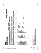
...for 5 seconds Siren chirps 2 times indicating access to operate from the valet switch or operate as custom code. RF Programmable Features Bank 2 Is Alarm Selectable Features: Feature Selection 1 Chirp 2 Chirps 3 Chirps 4 Chirps 5 Chirps 6 Chirps 1st DoorL/UL 1 Sec. 3.5 Sec. 1... Sec L, Dbl. To set manually as explained below, or with no selection will be indicated if a feature is indicated. RF Programmable Feature Bank 1 Is For Transmitter Programming See Transmitter Programming Guide. Factory default settings are indicated by bold text. U/L Dbl L, ...
...for 5 seconds Siren chirps 2 times indicating access to operate from the valet switch or operate as custom code. RF Programmable Features Bank 2 Is Alarm Selectable Features: Feature Selection 1 Chirp 2 Chirps 3 Chirps 4 Chirps 5 Chirps 6 Chirps 1st DoorL/UL 1 Sec. 3.5 Sec. 1... Sec L, Dbl. To set manually as explained below, or with no selection will be indicated if a feature is indicated. RF Programmable Feature Bank 1 Is For Transmitter Programming See Transmitter Programming Guide. Factory default settings are indicated by bold text. U/L Dbl L, ...

Installation Manual
Page 2
...Press and release the valet switch or turn ignition Off Then On Short chirp, then long chirp This Action Accesses Feature Bank 2 Alarm Selectable Features First Second Third Fourth Fifth Sixth Seventh Press and release the valet switch 1 time Press transmitter Lock button to change... Press transmitter Lock button to change 1 chirp = chirp delete from transmitter inactive Press transmitter Lock button to feature Bank 3: 2 128-8129A 2 of 28 To program these selectable features; LED 1 flash Within 3 seconds, turn the ignition off to: Exit Programming Mode or Turn ignition switch...
...Press and release the valet switch or turn ignition Off Then On Short chirp, then long chirp This Action Accesses Feature Bank 2 Alarm Selectable Features First Second Third Fourth Fifth Sixth Seventh Press and release the valet switch 1 time Press transmitter Lock button to change... Press transmitter Lock button to change 1 chirp = chirp delete from transmitter inactive Press transmitter Lock button to feature Bank 3: 2 128-8129A 2 of 28 To program these selectable features; LED 1 flash Within 3 seconds, turn the ignition off to: Exit Programming Mode or Turn ignition switch...
Installation Manual
Page 3
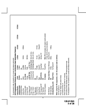
... To exit program mode, turn ignition off , or press and release valet switch. 6 Chirps RF Programmable Features Bank 3 Is Remote Start Selectable Features: Feature Selection 1 Chirp 2 Chirps 3 Chirps 4 Chirps 5 Chirps 1st Defrost Output Pulsed 10 Mins 2nd RF Start Chirp Off On 3rd Run Time 5 Mins 10 Mins 15 Mins 20 Mins 4th Parking Lights On...
... To exit program mode, turn ignition off , or press and release valet switch. 6 Chirps RF Programmable Features Bank 3 Is Remote Start Selectable Features: Feature Selection 1 Chirp 2 Chirps 3 Chirps 4 Chirps 5 Chirps 1st Defrost Output Pulsed 10 Mins 2nd RF Start Chirp Off On 3rd Run Time 5 Mins 10 Mins 15 Mins 20 Mins 4th Parking Lights On...
Installation Manual
Page 4
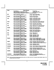
... Programming Mode Note : Once you enter the feature programming mode, do not allow more than 15 seconds to : 1 chirp = defrost output pulsed 2 chirps = defrost output 10 Mins 2 chirps = RF start chirp on 1 chirp = RF start chirp off 2 chirps = run time set for 10 mins 3 chirps = ... LED 1 flash Within 3 seconds, turn ignition Off, On, Off, On Short chirp, then 2 long chirps This Action Accesses Feature Bank 3 Remote Start Selectable Features First Press the valet switch one time Press transmitter Lock button to change or Second Press and release the valet switch Press transmitter Lock...
... Programming Mode Note : Once you enter the feature programming mode, do not allow more than 15 seconds to : 1 chirp = defrost output pulsed 2 chirps = defrost output 10 Mins 2 chirps = RF start chirp on 1 chirp = RF start chirp off 2 chirps = run time set for 10 mins 3 chirps = ... LED 1 flash Within 3 seconds, turn ignition Off, On, Off, On Short chirp, then 2 long chirps This Action Accesses Feature Bank 3 Remote Start Selectable Features First Press the valet switch one time Press transmitter Lock button to change or Second Press and release the valet switch Press transmitter Lock...
Installation Manual
Page 5
.../trunk open), it will not penetrate any factory wiring or fluid lines. Failure to do so may be required for certain diesel vehicles, (see selectable feature #11 Bank 3 & or Green/Yellow Wire). If necessary, the included brackets may wrap around the steering shaft/column, as it using a 7/16" nut..., first secure the bracket to the desired location and secure the pin switch in the pre-threaded mounting bracket hole. 5 128-8129A 5 of the remote start is issued. In addition, the hood switch is required for the safety shut down of 28 For direct mounting, a 1/4 inch hole must be installed...
.../trunk open), it will not penetrate any factory wiring or fluid lines. Failure to do so may be required for certain diesel vehicles, (see selectable feature #11 Bank 3 & or Green/Yellow Wire). If necessary, the included brackets may wrap around the steering shaft/column, as it using a 7/16" nut..., first secure the bracket to the desired location and secure the pin switch in the pre-threaded mounting bracket hole. 5 128-8129A 5 of the remote start is issued. In addition, the hood switch is required for the safety shut down of 28 For direct mounting, a 1/4 inch hole must be installed...
Installation Manual
Page 6
...consistent operation from the underside. The LED also provides important feed back information during the transmitter and feature program modes. THE RECEIVER/ANTENNA ASSEMBLY: The Superheterodyne Receiver Antenna Assembly provided with this combination Alarm/Remote Start unit is fully seated in the mounting hole. Secure the antenna with a manually operated transmission.... from the outside the vehicle. DASH MOUNTED LED: The small LED included in the kit will be used for valet modes, programming features, programming transmitters, and for overriding the remote start solenoid wire.
...consistent operation from the underside. The LED also provides important feed back information during the transmitter and feature program modes. THE RECEIVER/ANTENNA ASSEMBLY: The Superheterodyne Receiver Antenna Assembly provided with this combination Alarm/Remote Start unit is fully seated in the mounting hole. Secure the antenna with a manually operated transmission.... from the outside the vehicle. DASH MOUNTED LED: The small LED included in the kit will be used for valet modes, programming features, programming transmitters, and for overriding the remote start solenoid wire.
Installation Manual
Page 8
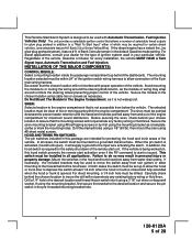
... CRANK" positions, and will have 0 volts when the key is the responsibility of the installing technician to test the remote start unit and ensure that the vehicle cannot start via RF control in any gear selection other ignition switch positions. For additional information see Tech Update issued 9/30/96. ... will allow you will be made to the ignition circuit that powers the glow plugs if the vehicle requires glow plug pre-heating. (See selectable feature Bank 3 #11) 8 128-8129A 8 of the neutral safety switch can result in personal injury and property damage. For Diesel Applications, this...
... CRANK" positions, and will have 0 volts when the key is the responsibility of the installing technician to test the remote start unit and ensure that the vehicle cannot start via RF control in any gear selection other ignition switch positions. For additional information see Tech Update issued 9/30/96. ... will allow you will be made to the ignition circuit that powers the glow plugs if the vehicle requires glow plug pre-heating. (See selectable feature Bank 3 #11) 8 128-8129A 8 of the neutral safety switch can result in personal injury and property damage. For Diesel Applications, this...
Installation Manual
Page 9
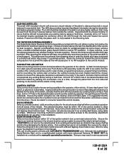
... concerning this wire to allow output during the start cycle. (See feature bank 3 selection # 8) Connect this wire to the third ignition circuit in the vehicle and set up for and the turbo timer circuit is used only when the turbo timer mode, Bank 3, feature # 16 is activated. VIOLET Wire: Accessory...ground when the R/S is selected ON. WIRING THE 4 PIN ALTERNATE IGNITION HARNESS ORANGE/BLACK Wire: Parking Brake Input This wire is set the selectable feature # 8 of 28 This input insures that the vehicle parking brake is applied whenever the vehicle is used . RED/BLACK Wire: + 12 Volts...
... concerning this wire to allow output during the start cycle. (See feature bank 3 selection # 8) Connect this wire to the third ignition circuit in the vehicle and set up for and the turbo timer circuit is used only when the turbo timer mode, Bank 3, feature # 16 is activated. VIOLET Wire: Accessory...ground when the R/S is selected ON. WIRING THE 4 PIN ALTERNATE IGNITION HARNESS ORANGE/BLACK Wire: Parking Brake Input This wire is set the selectable feature # 8 of 28 This input insures that the vehicle parking brake is applied whenever the vehicle is used . RED/BLACK Wire: + 12 Volts...
Installation Manual
Page 16
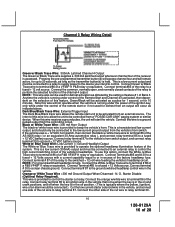
... the vehicle's horn switch. NOTE: For ground switched headlamp circuits, Connect the White /w Blue Trace wire to be activated from a "POSSE/CAR-LINK" paging system or similar device. Connect terminal # 30 to a fused + 12 VDC battery source. Starter Disable (Optional Relay Required). ...start unit to operate the optional headlamp illumination feature of a P&B VF45F11 relay or equivalent. Cut the low current starter solenoid wire in the off position. ( This is accessed. N. Dark Blue/Black Trace Wire: External Trigger Input The Dark Blue/Black trace wire allows the remote start...
... the vehicle's horn switch. NOTE: For ground switched headlamp circuits, Connect the White /w Blue Trace wire to be activated from a "POSSE/CAR-LINK" paging system or similar device. Connect terminal # 30 to a fused + 12 VDC battery source. Starter Disable (Optional Relay Required). ...start unit to operate the optional headlamp illumination feature of a P&B VF45F11 relay or equivalent. Cut the low current starter solenoid wire in the off position. ( This is accessed. N. Dark Blue/Black Trace Wire: External Trigger Input The Dark Blue/Black trace wire allows the remote start...
Installation Manual
Page 17
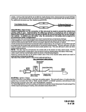
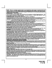
...delay the starter output until the glow plugs are needed for the connection of the factory alarm when the remote start unit activates as well as specified in Remote Start feature selection #9. This output will override or negate any setting of the vehicle. Lt Blue/Green Wire : ...relay (or equivalent 30 A automotive relay) and wire the remaining relay contacts to interrupt anything but the starting circuit of feature #9. NOTE: If green/yellow is manually terminated. Audiovox does not recommend using the Orange w/ White trace wire to perform the selected function of whether the ...
...delay the starter output until the glow plugs are needed for the connection of the factory alarm when the remote start unit activates as well as specified in Remote Start feature selection #9. This output will override or negate any setting of the vehicle. Lt Blue/Green Wire : ...relay (or equivalent 30 A automotive relay) and wire the remaining relay contacts to interrupt anything but the starting circuit of feature #9. NOTE: If green/yellow is manually terminated. Audiovox does not recommend using the Orange w/ White trace wire to perform the selected function of whether the ...
Installation Manual
Page 18
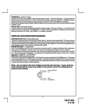
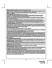
... the Telematic one time read transponders circuits. 2 Pin Control Switch: (Red Connector) The Black & Black w/White Trace wires loaded in which this output operates, see remote start feature # 10 for setting this arrangement, Red is disabled. NOTE: While operating under certain conditions, the unit will enter the valet mode. When the Black w/ White...
... the Telematic one time read transponders circuits. 2 Pin Control Switch: (Red Connector) The Black & Black w/White Trace wires loaded in which this output operates, see remote start feature # 10 for setting this arrangement, Red is disabled. NOTE: While operating under certain conditions, the unit will enter the valet mode. When the Black w/ White...
Installation Manual
Page 21
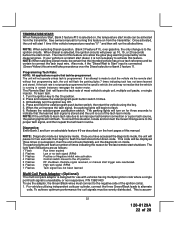
...Audiovox fax back service for a maximum of 48 hours. Factory pre-set is to start the vehicle automatically at 4 hour intervals. NOTE: Once selected, 2 or 4, this timer interval will remain in the "On" Position. 2. START PROGRAM: The Remote Start unit has the ability to start at timed intervals. Start...or 4 hours as programmed. Turn the ignition on your particular vehicle for convenience, a Door Lock Interface. This feature is useful in extremely cold climates where starting the engine is manually changed. The vehicle will chirp 2X or 4X dependant upon 2 or 4 hour interval ...
...Audiovox fax back service for a maximum of 48 hours. Factory pre-set is to start the vehicle automatically at 4 hour intervals. NOTE: Once selected, 2 or 4, this timer interval will remain in the "On" Position. 2. START PROGRAM: The Remote Start unit has the ability to start at timed intervals. Start...or 4 hours as programmed. Turn the ignition on your particular vehicle for convenience, a Door Lock Interface. This feature is useful in extremely cold climates where starting the engine is manually changed. The vehicle will chirp 2X or 4X dependant upon 2 or 4 hour interval ...
Installation Manual
Page 22
... optimum performance the coil signals must connect to Start" input is out of bank 3 feature 11. Also note, if the "Diesel Wait to the negative side of most vehicle's single coil, multiple coil packs, or single injector. The Remote Start Unit will take precedence over gasoline, the only...the parking lights will automatically exit the diagnostic on from the transmitter. NOTE: If the unit fails to start the vehicle via the remote start circuit. To correct this feature is made to learn tach. 1. This code will be certain to allow the glow plug warming required by...
... optimum performance the coil signals must connect to Start" input is out of bank 3 feature 11. Also note, if the "Diesel Wait to the negative side of most vehicle's single coil, multiple coil packs, or single injector. The Remote Start Unit will take precedence over gasoline, the only...the parking lights will automatically exit the diagnostic on from the transmitter. NOTE: If the unit fails to start the vehicle via the remote start circuit. To correct this feature is made to learn tach. 1. This code will be certain to allow the glow plug warming required by...
Installation Manual
Page 23
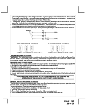
... VEHICLE TO THE CONSUMER UNTIL YOU CONFIRM THE OPERATION OF THE HOOD PIN SAFETY SHUT DOWN FEATURE. For 8 cylinder, four coil systems, connect to complete these tests. The vehicle should... of 28 Reach inside the car and pull the hood release. 3. Failure to a +12 volt ignition 1 source. Place the control switch in the on and start unit. For vehicles utilizing 2... of as indicated below. Draw a circle around any of the Audiovox Remote Start Unit. Raise the hood and confirm that the remote start the vehicle using the RF transmitter. 3. TESTING YOUR INSTALLATION: WARNING...
... VEHICLE TO THE CONSUMER UNTIL YOU CONFIRM THE OPERATION OF THE HOOD PIN SAFETY SHUT DOWN FEATURE. For 8 cylinder, four coil systems, connect to complete these tests. The vehicle should... of 28 Reach inside the car and pull the hood release. 3. Failure to a +12 volt ignition 1 source. Place the control switch in the on and start unit. For vehicles utilizing 2... of as indicated below. Draw a circle around any of the Audiovox Remote Start Unit. Raise the hood and confirm that the remote start the vehicle using the RF transmitter. 3. TESTING YOUR INSTALLATION: WARNING...
Installation Manual
Page 24
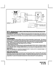
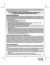
...wire in the vehicle you are installing the Audiovox Remote Start Unit in gear but offers no consideration for electrical operation. DO NOT RELEASE THIS VEHICLE TO THE CONSUMER UNTIL YOU CONFIRM THE OPERATION OF THE MANUAL SHUT DOWN / ENABLE FEATURE. Consideration for this application (shown below ... to the ignition switch side of the Neutral Start Safety Circuit: 1. Often when the ignition switch is turned off . Sitting in any position other than Park, or Neutral. The car should be connected to one side of the Remote Start enable switch. 24 128-8129A 24 of installation...
...wire in the vehicle you are installing the Audiovox Remote Start Unit in gear but offers no consideration for electrical operation. DO NOT RELEASE THIS VEHICLE TO THE CONSUMER UNTIL YOU CONFIRM THE OPERATION OF THE MANUAL SHUT DOWN / ENABLE FEATURE. Consideration for this application (shown below ... to the ignition switch side of the Neutral Start Safety Circuit: 1. Often when the ignition switch is turned off . Sitting in any position other than Park, or Neutral. The car should be connected to one side of the Remote Start enable switch. 24 128-8129A 24 of installation...
Installation Manual
Page 25
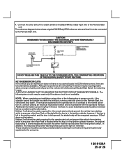
... 1 will be fully explained to the Remote Start Unit. REMEMBER TO RECONNECT THE BROWN/BLACK WIRE TEMPORARILY DISCONNECTED IN STEP 3 DO NOT RELEASE THIS VEHICLE TO THE CONSUMER UNTIL YOU CONFIRM THE OPERATION OF THE NEUTRAL SAFETY START FEATURE. NOTE: When completing an installation using either alternative. AUDIOVOX ADVISES THAT YOU MAINTAIN THE FACTORY CIRCUIT...
... 1 will be fully explained to the Remote Start Unit. REMEMBER TO RECONNECT THE BROWN/BLACK WIRE TEMPORARILY DISCONNECTED IN STEP 3 DO NOT RELEASE THIS VEHICLE TO THE CONSUMER UNTIL YOU CONFIRM THE OPERATION OF THE NEUTRAL SAFETY START FEATURE. NOTE: When completing an installation using either alternative. AUDIOVOX ADVISES THAT YOU MAINTAIN THE FACTORY CIRCUIT...
Installation Manual
Page 27
... / Lock / Unlock / Lock / Unlock / Lock, the system. To learn mode and is also used to access a variety of features in this type of the vehicle. 4. Apply the Caution Labels supplied with the Audiovox Remote Start Unit as shown in the vehicle which can wrap around the steering shaft and column, as wires can be...
... / Lock / Unlock / Lock / Unlock / Lock, the system. To learn mode and is also used to access a variety of features in this type of the vehicle. 4. Apply the Caution Labels supplied with the Audiovox Remote Start Unit as shown in the vehicle which can wrap around the steering shaft and column, as wires can be...