Installation Manual
Page 3
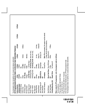
... off , or press and release valet switch. 6 Chirps RF Programmable Features Bank 3 Is Remote Start Selectable Features: Feature Selection 1 Chirp 2 Chirps 3 Chirps 4 Chirps 5 Chirps 1st Defrost Output Pulsed 10 Mins 2nd RF Start Chirp Off On 3rd Run Time 5 Mins 10 Mins 15 Mins 20 Mins 4th Parking Lights... On Steady Flashing 5th Input Check Voltage Tach DBI Tach 6th Voltage Level >0.5V B4 Start < 0.5V B4 Start 7th Ign. 2 Select Off During Crank On During Crank Same As Accy. 8th Ign. 3 Select Off During Crank On During ...
... off , or press and release valet switch. 6 Chirps RF Programmable Features Bank 3 Is Remote Start Selectable Features: Feature Selection 1 Chirp 2 Chirps 3 Chirps 4 Chirps 5 Chirps 1st Defrost Output Pulsed 10 Mins 2nd RF Start Chirp Off On 3rd Run Time 5 Mins 10 Mins 15 Mins 20 Mins 4th Parking Lights... On Steady Flashing 5th Input Check Voltage Tach DBI Tach 6th Voltage Level >0.5V B4 Start < 0.5V B4 Start 7th Ign. 2 Select Off During Crank On During Crank Same As Accy. 8th Ign. 3 Select Off During Crank On During ...
Installation Manual
Page 4
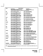
... 3 seconds, turn ignition Off, On, Off, On Short chirp, then 2 long chirps This Action Accesses Feature Bank 3 Remote Start Selectable Features First Press the valet switch one time Press transmitter Lock button to change or Second Press and release the valet switch...preset crank time w/voltage input check 1 chirp = shk sensor shunted until clear 2 chirps = shk sensor shunted for the R/S Cycle 3 chirps = shk sensor shunted from tx 1 start cycle 1 chirp = turbo timer off 2 chirps = turbo timer 3 mins 3 chirps = turbo timer 5 mins 4 chirps = turbo timer 10 mins 1 chirp = aux o/p Black...
... 3 seconds, turn ignition Off, On, Off, On Short chirp, then 2 long chirps This Action Accesses Feature Bank 3 Remote Start Selectable Features First Press the valet switch one time Press transmitter Lock button to change or Second Press and release the valet switch...preset crank time w/voltage input check 1 chirp = shk sensor shunted until clear 2 chirps = shk sensor shunted for the R/S Cycle 3 chirps = shk sensor shunted from tx 1 start cycle 1 chirp = turbo timer off 2 chirps = turbo timer 3 mins 3 chirps = turbo timer 5 mins 4 chirps = turbo timer 10 mins 1 chirp = aux o/p Black...
Installation Manual
Page 5
... mounting holes. In addition, the hood switch is required for the type of ignition system used in addition to a "Wait To Start Input" either of the remote start is issued. Regardless of the vehicle, Gasoline or Diesel, for protecting the hood and trunk areas of 28 Secure the module in... mounting bracket, first secure the bracket to the desired location and secure the pin switch in this hood switch prevents the remote start activation even if the RF command to start unit. HOOD AND TRUNK PIN SWITCHES: The pin switches included in the pre-threaded mounting bracket hole. 5 128-8129A ...
... mounting holes. In addition, the hood switch is required for the type of ignition system used in addition to a "Wait To Start Input" either of the remote start is issued. Regardless of the vehicle, Gasoline or Diesel, for protecting the hood and trunk areas of 28 Secure the module in... mounting bracket, first secure the bracket to the desired location and secure the pin switch in this hood switch prevents the remote start activation even if the RF command to start unit. HOOD AND TRUNK PIN SWITCHES: The pin switches included in the pre-threaded mounting bracket hole. 5 128-8129A ...
Installation Manual
Page 6
... into place until the switch is to be within 12" of the switch, and also that adequate clearance is allowed for overriding the remote start solenoid wire. The sensor can also be made for use later in the installation. Secure the relay to an existing harness in the ...chosen location using two #8 self tapping sheet metal screws. CAUTION! Although this combination Alarm/Remote Start unit is a sophisticated system with many advanced features, IT MUST NOT be visible from below the dash board for best reception. DASH MOUNTED LED...
... into place until the switch is to be within 12" of the switch, and also that adequate clearance is allowed for overriding the remote start solenoid wire. The sensor can also be made for use later in the installation. Secure the relay to an existing harness in the ...chosen location using two #8 self tapping sheet metal screws. CAUTION! Although this combination Alarm/Remote Start unit is a sophisticated system with many advanced features, IT MUST NOT be visible from below the dash board for best reception. DASH MOUNTED LED...
Installation Manual
Page 8
... configurations. For Diesel Applications, this connection properly can result in personal injury and property damage. In addition you to test the remote start unit and ensure that the vehicle cannot start switch configurations, the connection of the ignition switch harness. This wire will realize why the connection of the safety wire is turned...
... configurations. For Diesel Applications, this connection properly can result in personal injury and property damage. In addition you to test the remote start unit and ensure that the vehicle cannot start switch configurations, the connection of the ignition switch harness. This wire will realize why the connection of the safety wire is turned...
Installation Manual
Page 11
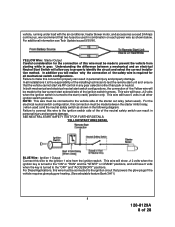
...disarm the alarm system. Hood Pin Switch Detail Light Blue Wire: Ground Output While Running Under Remote Start Control This wire provides a 300mA ground output that becomes active 3 seconds before the Remote Start Unit initializes and remains grounded while running under title "Completing The Installation". In most door ...remain shunted all of 28 This wire will emit three chirps. This wire will need to only one of the remote start. Note for 5 seconds after the Remote Start Unit turns off. If this wire to the positive output from one door switch no matter how many doors the...
...disarm the alarm system. Hood Pin Switch Detail Light Blue Wire: Ground Output While Running Under Remote Start Control This wire provides a 300mA ground output that becomes active 3 seconds before the Remote Start Unit initializes and remains grounded while running under title "Completing The Installation". In most door ...remain shunted all of 28 This wire will emit three chirps. This wire will need to only one of the remote start. Note for 5 seconds after the Remote Start Unit turns off. If this wire to the positive output from one door switch no matter how many doors the...
Installation Manual
Page 12
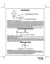
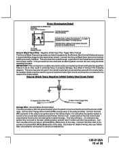
... of 28 Connect the other end of the cut wire to terminal #86 of the relay. For GM PASS LOCK System you will require the Audiovox AS-PASS II Module. C. Cut (#1) wire (as shown). General Motors VATS By-Pass Diagram Green w/ White trace Wire: Entry Illumination Ground Output... while the vehicle is triggered. Locate the pair of a external relay. Connect the Light Blue Wire from the resistor pack supplied. 2. Just before the Remote Start unit is a Non Plug in the vehicle, usually a pair of the (#1) wire to terminal #30 and the other side of thin gauge wires running...
... of 28 Connect the other end of the cut wire to terminal #86 of the relay. For GM PASS LOCK System you will require the Audiovox AS-PASS II Module. C. Cut (#1) wire (as shown). General Motors VATS By-Pass Diagram Green w/ White trace Wire: Entry Illumination Ground Output... while the vehicle is triggered. Locate the pair of a external relay. Connect the Light Blue Wire from the resistor pack supplied. 2. Just before the Remote Start unit is a Non Plug in the vehicle, usually a pair of the (#1) wire to terminal #30 and the other side of thin gauge wires running...
Installation Manual
Page 13
... Black Trace Wire: Negative Inhibit Input Plus Trigger When Armed The Grey w/ Black Trace wire provides an instant shutdown for the Remote Start Control Module whenever it is moved to the start (crank) position and will have + 12 volts when the ignition key is grounded also trigger for the alarm when armed.... Armed Output This wire provides a 300 mA ground output when the alarm circuit is off when the key is armed to the on and start solenoid wire found at the vehicles ignition switch harness. This wire must be routed through a grommet in the following diagram. See detail of ...
... Black Trace Wire: Negative Inhibit Input Plus Trigger When Armed The Grey w/ Black Trace wire provides an instant shutdown for the Remote Start Control Module whenever it is moved to the start (crank) position and will have + 12 volts when the ignition key is grounded also trigger for the alarm when armed.... Armed Output This wire provides a 300 mA ground output when the alarm circuit is off when the key is armed to the on and start solenoid wire found at the vehicles ignition switch harness. This wire must be routed through a grommet in the following diagram. See detail of ...
Installation Manual
Page 14
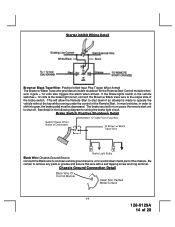
...Black trace wire to shift into gear, the brake pedal must be depressed. Be certain to shut off. See detail in turn cause the remote start unit to remove any paint or grease and secure this wire with a self tapping screw and ring terminal. Starter Inhibit Wiring Detail White/... to a solid clean metal part of the brake switch. Chassis Ground Connection Detail 14 128-8129A 14 of the Remote Start. This will in the following diagram for the Remote Start Control module whenever it gets + 12 volts also triggers the alarm when armed. Brake Switch Positive Shutdown Detail Black Wire...
...Black trace wire to shift into gear, the brake pedal must be depressed. Be certain to shut off. See detail in turn cause the remote start unit to remove any paint or grease and secure this wire with a self tapping screw and ring terminal. Starter Inhibit Wiring Detail White/... to a solid clean metal part of the brake switch. Chassis Ground Connection Detail 14 128-8129A 14 of the Remote Start. This will in the following diagram for the Remote Start Control module whenever it gets + 12 volts also triggers the alarm when armed. Brake Switch Positive Shutdown Detail Black Wire...
Installation Manual
Page 15
...continually monitor the engine's tach rate while the unit is opened, (Most GMs and Imports), you wish to the negative side of the remote start. Negative Door Switch Wiring Detail Dark Blue Wire: Delayed 300mA Pulsed Channel 3 Output The Dark Blue wire supplies a 300mA ground pulsed output...and connect to control. See below for three seconds will remain shunted, if active, while running under title "Completing The Installation". This Remote Start unit learns the tach rate of cylinders. See multi coil wiring detail shown later in most cases the Brown wire will operate properly ...
...continually monitor the engine's tach rate while the unit is opened, (Most GMs and Imports), you wish to the negative side of the remote start. Negative Door Switch Wiring Detail Dark Blue Wire: Delayed 300mA Pulsed Channel 3 Output The Dark Blue wire supplies a 300mA ground pulsed output...and connect to control. See below for three seconds will remain shunted, if active, while running under title "Completing The Installation". This Remote Start unit learns the tach rate of cylinders. See multi coil wiring detail shown later in most cases the Brown wire will operate properly ...
Installation Manual
Page 16
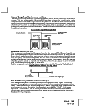
...is provided to operate the optional headlamp illumination feature of the system. Connect terminal # 87 to the low current ground output from a "POSSE/CAR-LINK" paging system or similar device. Orange w/ White Trace Wire : 300 mA Ground Output When Disarmed - O. This wire is to ... output will remain active, for 10 minutes. Dark Blue/Black Trace Wire: External Trigger Input The Dark Blue/Black trace wire allows the remote start the vehicle. Anytime the vehicle is typically where the yellow, (ignition), wire of a P&B VF45F11 relay or equivalent. Connect relay terminal 87...
...is provided to operate the optional headlamp illumination feature of the system. Connect terminal # 87 to the low current ground output from a "POSSE/CAR-LINK" paging system or similar device. Orange w/ White Trace Wire : 300 mA Ground Output When Disarmed - O. This wire is to ... output will remain active, for 10 minutes. Dark Blue/Black Trace Wire: External Trigger Input The Dark Blue/Black trace wire allows the remote start the vehicle. Anytime the vehicle is typically where the yellow, (ignition), wire of a P&B VF45F11 relay or equivalent. Connect relay terminal 87...
Installation Manual
Page 17
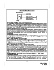
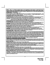
... Trace Wire: Pulsed Ground Output After Shutdown The Black w/ Red Trace wire will provide a 1 second 300mA pulsed ground output after the remote start unit activates as well as when the transmitter is a transistorized, low current output, and should only be used to perform the selected function... of channel 7. This output will damage the control module. Audiovox does not recommend using the Orange w/ White trace wire to disarm the system. Blue/Red Wire : DELAYED 300 mA PULSED OUTPUT / ...
... Trace Wire: Pulsed Ground Output After Shutdown The Black w/ Red Trace wire will provide a 1 second 300mA pulsed ground output after the remote start unit activates as well as when the transmitter is a transistorized, low current output, and should only be used to perform the selected function... of channel 7. This output will damage the control module. Audiovox does not recommend using the Orange w/ White trace wire to disarm the system. Blue/Red Wire : DELAYED 300 mA PULSED OUTPUT / ...
Installation Manual
Page 18
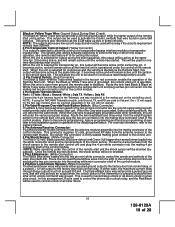
...control module. In either a pulsed ground output to the factory door lock control relay, or a pulsed + 12 volt output to the remote start unit the shock sensor will be sourced separately or the unit will not operate. 2 Pin Valet/Program/Override Push-Button Switch: (Blue Connector...Black w/White Trace wires loaded in which this installation guide for continuous read transponder circuits. NOTE: While operating under the control of the Remote Start unit. This will enter the valet mode. Route the twin lead Black & Black w/ White Trace wires from the antenna receiver to ...
...control module. In either a pulsed ground output to the factory door lock control relay, or a pulsed + 12 volt output to the remote start unit the shock sensor will be sourced separately or the unit will not operate. 2 Pin Valet/Program/Override Push-Button Switch: (Blue Connector...Black w/White Trace wires loaded in which this installation guide for continuous read transponder circuits. NOTE: While operating under the control of the Remote Start unit. This will enter the valet mode. Route the twin lead Black & Black w/ White Trace wires from the antenna receiver to ...
Installation Manual
Page 21
... turning off, cycle the enable switch Off, On, Off, On ( 2 times) to select a 2 hour timed start interval. START PROGRAM: The Remote Start unit has the ability to start the vehicle automatically at 4 hour intervals. The lights will flash and the siren will remain in memory until it is...change, the above sequence will have the unit start button four times). To cancel the timed start mode start interval. Refer to the AUDIOVOX Door Lock Wiring Supplement and or the Audiovox fax back service for properly connecting to select a 4 hour timed start the vehicle either by RF or by the ...
... turning off, cycle the enable switch Off, On, Off, On ( 2 times) to select a 2 hour timed start interval. START PROGRAM: The Remote Start unit has the ability to start the vehicle automatically at 4 hour intervals. The lights will flash and the siren will remain in memory until it is...change, the above sequence will have the unit start button four times). To cancel the timed start mode start interval. Refer to the AUDIOVOX Door Lock Wiring Supplement and or the Audiovox fax back service for properly connecting to select a 4 hour timed start the vehicle either by RF or by the ...
Installation Manual
Page 22
... key to the ignition circuits. To achieve optimum performance the coil signals must connect to the off position 5 Flashes RF shutdown, Remote signal received, or manual start circuit. This is a temporary mode. NOTE: When selecting Diesel operation, (Bank 3 Feature #11), over the Diesel selection of...NOTE: When selecting Diesel mode, be certain that the intended vehicle has a true tach reference and be certain to start the vehicle via the remote start mode can be programmed. If an attempt is not necessary to activate this situation, locate and connect the Green/Orange...
... key to the ignition circuits. To achieve optimum performance the coil signals must connect to the off position 5 Flashes RF shutdown, Remote signal received, or manual start circuit. This is a temporary mode. NOTE: When selecting Diesel operation, (Bank 3 Feature #11), over the Diesel selection of...NOTE: When selecting Diesel mode, be certain that the intended vehicle has a true tach reference and be certain to start the vehicle via the remote start mode can be programmed. If an attempt is not necessary to activate this situation, locate and connect the Green/Orange...
Installation Manual
Page 23
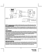
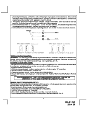
... maintenance. Reach inside the car and pull the hood release. 3. To test the integrity of the columns. Raise the hood and confirm that the remote start unit. The Green/Black wires should be performed after the installation of the Audiovox remote start unit shuts down. The ... 3. Connect the Green wire to prevent operation of the Remote Start Unit regardless of the Audiovox Remote Start Unit. It is to allow the vehicle operator to the (Green) or (Orange/Green) tach input of an Audiovox Remote Start Device. To test the integrity of as indicated below. With...
... maintenance. Reach inside the car and pull the hood release. 3. To test the integrity of the columns. Raise the hood and confirm that the remote start unit. The Green/Black wires should be performed after the installation of the Audiovox remote start unit shuts down. The ... 3. Connect the Green wire to prevent operation of the Remote Start Unit regardless of the Audiovox Remote Start Unit. It is to allow the vehicle operator to the (Green) or (Orange/Green) tach input of an Audiovox Remote Start Device. To test the integrity of as indicated below. With...
Installation Manual
Page 24
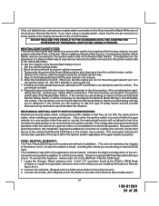
... selectors position. This connection will be necessary to reconfigure the Remote Starts Wiring to prevent the vehicle from the remote start device to remove the key. 7. To connect the Audiovox remote start unit to one side of the Remote Start enable switch. 24 128-8129A 24 of installation. Connect the...The installation required for electrical operation. When you are working on the brake pedal and shift the gear selector into reverse. 6. The car should be removed from the vehicle's brake switch. 4. Often when the ignition switch is turned off . Locate the Orange / ...
... selectors position. This connection will be necessary to reconfigure the Remote Starts Wiring to prevent the vehicle from the remote start device to remove the key. 7. To connect the Audiovox remote start unit to one side of the Remote Start enable switch. 24 128-8129A 24 of installation. Connect the...The installation required for electrical operation. When you are working on the brake pedal and shift the gear selector into reverse. 6. The car should be removed from the vehicle's brake switch. 4. Often when the ignition switch is turned off . Locate the Orange / ...
Installation Manual
Page 25
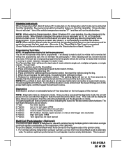
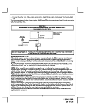
...NEUTRAL SAFETY START FEATURE. NOTE...Start Switch from starting...Remote Start unit. Method 2 will allow the safety required for the remote start unit and prevent the vehicle from starting... while in chime module will not alert the owner that the key has been left opened, the added relay will be connected to the Black/White enable input wire of 28 CAUTION! Method 1 will allow the safety required for the remote start... unit and prevent the vehicle from starting...the Remote Start Unit...side of the Remote Start, the vehicle ...
...NEUTRAL SAFETY START FEATURE. NOTE...Start Switch from starting...Remote Start unit. Method 2 will allow the safety required for the remote start unit and prevent the vehicle from starting... while in chime module will not alert the owner that the key has been left opened, the added relay will be connected to the Black/White enable input wire of 28 CAUTION! Method 1 will allow the safety required for the remote start... unit and prevent the vehicle from starting...the Remote Start Unit...side of the Remote Start, the vehicle ...
Installation Manual
Page 26
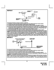
...Cut this is also used for method 2: A. The cathode (Striped) side must be certain to use the dual diode assembly packaged with the Audiovox Remote Start Unit as shown in this wire and connect the ignition cylinder side to terminal 30 of the pin switch wire previously cut wire in step... D. Connect terminal 86 of the Audiovox Remote Start Unit. The anode (Non Striped) side must 26 128-8129A 26 of the Remote Start Unit. B. D. H. D. METHOD 1 To connect to the key in sensor as shown in the diagram ...
...Cut this is also used for method 2: A. The cathode (Striped) side must be certain to use the dual diode assembly packaged with the Audiovox Remote Start Unit as shown in this wire and connect the ignition cylinder side to terminal 30 of the pin switch wire previously cut wire in step... D. Connect terminal 86 of the Audiovox Remote Start Unit. The anode (Non Striped) side must 26 128-8129A 26 of the Remote Start Unit. B. D. H. D. METHOD 1 To connect to the key in sensor as shown in the diagram ...
Installation Manual
Page 27
... these mechanisms and impair the safe operation of this port other than the Audiovox IDB modules or damage to the Remote Start module will occur. Retest by following the steps outlined in the NEUTRAL START SAFETY TEST shown in the engine compartment areas. DO NOT connect anything to...and behind the dash securing it in place with the Audiovox Remote Start Unit as the proper voltage levels for an alarm trigger input, be connected to distinguish the Remote Start control switch from all the safety features of the Audiovox Remote Start unit and tested all hot and moving parts that the ...
... these mechanisms and impair the safe operation of this port other than the Audiovox IDB modules or damage to the Remote Start module will occur. Retest by following the steps outlined in the NEUTRAL START SAFETY TEST shown in the engine compartment areas. DO NOT connect anything to...and behind the dash securing it in place with the Audiovox Remote Start Unit as the proper voltage levels for an alarm trigger input, be connected to distinguish the Remote Start control switch from all the safety features of the Audiovox Remote Start unit and tested all hot and moving parts that the ...


