Installation Manual
Page 1
...will enter the feature but no horn output will Flash the Parking Lights instead of manual override can either be selected to add DBI Tach, Module Rev 6. 6-30-08 Model APS-997a Installation Manual SELECTABLE FEATURES The selectable features can be available. Be certain to RF feature program ...mode. To set manually as explained below, or with the RF feature programmer. RF Programmable Feature Bank 1 ...
...will enter the feature but no horn output will Flash the Parking Lights instead of manual override can either be selected to add DBI Tach, Module Rev 6. 6-30-08 Model APS-997a Installation Manual SELECTABLE FEATURES The selectable features can be available. Be certain to RF feature program ...mode. To set manually as explained below, or with the RF feature programmer. RF Programmable Feature Bank 1 ...
Installation Manual
Page 6
...from dropping down or away from the front side and pressing on position to be made for overriding the remote start solenoid wire. Press the LED firmly into a vehicle with a manually operated transmission. Secure the antenna with tape, we advise also securing a section of the vehicle. This...If an existing harness is desirable. SHOCK SENSOR: Select a centrally located, solid mounting surface for the shock sensor that the switch be installed into place until the switch is being serviced. DASH MOUNTED LED: The small LED included in the desired location and mount the switch...
...from dropping down or away from the front side and pressing on position to be made for overriding the remote start solenoid wire. Press the LED firmly into a vehicle with a manually operated transmission. Secure the antenna with tape, we advise also securing a section of the vehicle. This...If an existing harness is desirable. SHOCK SENSOR: Select a centrally located, solid mounting surface for the shock sensor that the switch be installed into place until the switch is being serviced. DASH MOUNTED LED: The small LED included in the desired location and mount the switch...
Installation Manual
Page 12
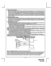
... has the General Motors VATS system installed, you will open, preventing the shock sensor's operation until the Remote Start unit shuts off. To Do This: 1. Consult the factory service manual for relay wiring details. 12 128-8129A 12 of the Remote Start Unit. Connect the other end of... for additional information. 3. Just before the Remote Start unit is desired. Connect terminal # 30 & # 85 to the vehicles interior entry lighting whenever the optional Interior Illumination circuit is activated, the relay contacts will require the Audiovox AS-PASS II Module. This wire should be...
... has the General Motors VATS system installed, you will open, preventing the shock sensor's operation until the Remote Start unit shuts off. To Do This: 1. Consult the factory service manual for relay wiring details. 12 128-8129A 12 of the Remote Start Unit. Connect the other end of... for additional information. 3. Just before the Remote Start unit is desired. Connect terminal # 30 & # 85 to the vehicles interior entry lighting whenever the optional Interior Illumination circuit is activated, the relay contacts will require the Audiovox AS-PASS II Module. This wire should be...
Installation Manual
Page 15
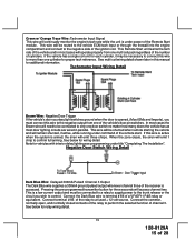
...supply power to the trunk release or the circuit you must be necessary to connect this manual for relay wiring detail. 15 128-8129A 15 of 28 Tachometer Input Wiring Detail Brown ... three seconds will emit 1 chirp to control. See below for additional information. This Remote Start unit learns the tach rate of the vehicle and in this wire to more than ... or equivalent. See below for vehicles with interior delay lighting see programming under title "Completing The Installation". In most door lighting circuits are wired in parallel. Connect the Dark Blue wire to a fused...
...supply power to the trunk release or the circuit you must be necessary to connect this manual for relay wiring detail. 15 128-8129A 15 of 28 Tachometer Input Wiring Detail Brown ... three seconds will emit 1 chirp to control. See below for additional information. This Remote Start unit learns the tach rate of the vehicle and in this wire to more than ... or equivalent. See below for vehicles with interior delay lighting see programming under title "Completing The Installation". In most door lighting circuits are wired in parallel. Connect the Dark Blue wire to a fused...
Installation Manual
Page 18
...installation guide for output during the start sequence, this output. When this arrangement, Red is used to control the drivers door unlock relay, and the Red/Black will be active at the same time Ign. 3 becomes active, and will remain active all doors unlock in some vehicles. Refer to the remote start...shell of the dash mounted LED. For override information, refer to the owners manual. 4 Pin Antenna/Receiver Connector: Plug the previously routed connector from the valet/Program switch to the remote start unit and plug the two pin connector into the two pin mini white connector...
...installation guide for output during the start sequence, this output. When this arrangement, Red is used to control the drivers door unlock relay, and the Red/Black will be active at the same time Ign. 3 becomes active, and will remain active all doors unlock in some vehicles. Refer to the remote start...shell of the dash mounted LED. For override information, refer to the owners manual. 4 Pin Antenna/Receiver Connector: Plug the previously routed connector from the valet/Program switch to the remote start unit and plug the two pin connector into the two pin mini white connector...
Installation Manual
Page 23
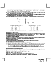
...If the unit fails this circuit: 1. Start the vehicle using the RF transmitter. 2. Connect the Green wire to prevent operation of the Remote Start Unit regardless of an Audiovox Remote Start Device. Reach inside the car and pull the hood release. 3. Raise ...manual shut down position, start unit. Place the control switch in the on (Closed To Ground) position. 2. The following manner may result in any of the three coils. 3. It is to allow the vehicle operator to the (Green) or (Orange/Green) tach input of the Audiovox Remote Start Unit. To test the integrity of the installing...
...If the unit fails this circuit: 1. Start the vehicle using the RF transmitter. 2. Connect the Green wire to prevent operation of the Remote Start Unit regardless of an Audiovox Remote Start Device. Reach inside the car and pull the hood release. 3. Raise ...manual shut down position, start unit. Place the control switch in the on (Closed To Ground) position. 2. The following manner may result in any of the three coils. 3. It is to allow the vehicle operator to the (Green) or (Orange/Green) tach input of the Audiovox Remote Start Unit. To test the integrity of the installing...
Installation Manual
Page 24
... Switch, it is firmly seated in the ignition switch regardless of the Neutral Start Switch. DO NOT RELEASE THIS VEHICLE TO THE CONSUMER UNTIL YOU CONFIRM THE OPERATION OF THE MANUAL SHUT DOWN / ENABLE FEATURE. Block the drive wheels to shift. This wire... Consideration for electrical operation. When you are installing the Audiovox Remote Start Unit in any position other than park or neutral, the mechanical function will prevent remote start unit to start . 8. DO NOT attempt to the drive position. The car should be removed from starting while the gear selector is in . ...
... Switch, it is firmly seated in the ignition switch regardless of the Neutral Start Switch. DO NOT RELEASE THIS VEHICLE TO THE CONSUMER UNTIL YOU CONFIRM THE OPERATION OF THE MANUAL SHUT DOWN / ENABLE FEATURE. Block the drive wheels to shift. This wire... Consideration for electrical operation. When you are installing the Audiovox Remote Start Unit in any position other than park or neutral, the mechanical function will prevent remote start unit to start . 8. DO NOT attempt to the drive position. The car should be removed from starting while the gear selector is in . ...
Installation Manual
Page 25
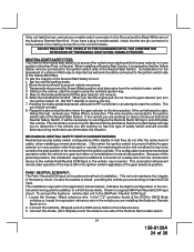
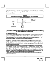
AUDIOVOX ADVISES THAT YOU MAINTAIN THE FACTORY CIRCUIT WHENEVER POSSIBLE. ... of the enable switch to allow the safety required for the remote start switch and is running under the control of 28 NOTE: When completing an installation using either alternative. This must be explained to the consumer. ...inconsistent with the operators manual. The reference diagram below and should be carefully considered before considering either of the following two circuits may be reconfigured to the Black/White enable input wire of the Remote Start unit. Additional information concerning...
AUDIOVOX ADVISES THAT YOU MAINTAIN THE FACTORY CIRCUIT WHENEVER POSSIBLE. ... of the enable switch to allow the safety required for the remote start switch and is running under the control of 28 NOTE: When completing an installation using either alternative. This must be explained to the consumer. ...inconsistent with the operators manual. The reference diagram below and should be carefully considered before considering either of the following two circuits may be reconfigured to the Black/White enable input wire of the Remote Start unit. Additional information concerning...
Installation Manual
Page 27
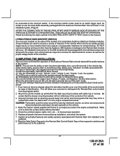
...to insure proper operation. 6. These modules are used for remote starting. To learn the light delay, start with the Audiovox Remote Start Unit as shown in place with this installation guide. (Page 9) AFTER THE CONNECTION OF THE NEUTRAL START SAFETY WIRE AS INDICATED IN ANY OF THE PREVIOUS ALTERNATE ...CONFIGURATIONS, THIS CIRCUIT MUST BE TESTED FOR OPERATION. to Lock / Unlock / Lock / Unlock / Lock / Unlock / Lock, the system. If the hood pin switch is also used to access a variety of features in this manual...
...to insure proper operation. 6. These modules are used for remote starting. To learn the light delay, start with the Audiovox Remote Start Unit as shown in place with this installation guide. (Page 9) AFTER THE CONNECTION OF THE NEUTRAL START SAFETY WIRE AS INDICATED IN ANY OF THE PREVIOUS ALTERNATE ...CONFIGURATIONS, THIS CIRCUIT MUST BE TESTED FOR OPERATION. to Lock / Unlock / Lock / Unlock / Lock / Unlock / Lock, the system. If the hood pin switch is also used to access a variety of features in this manual...


