Installation Manual
Page 1
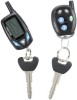
...-08 Model APS-997a Installation Manual SELECTABLE FEATURES The selectable features can either be selected to RF feature program mode. RF Programmable Features Bank 2 Is Alarm Selectable Features: Feature Selection 1 Chirp 2 Chirps 3 Chirps 4 Chirps 5 Chirps 6 Chirps 1st DoorL/UL 1 Sec. 3.5 Sec. 1 Sec L, Dbl. U/L Dbl L, 1 Sec UL Dbl L, Dbl UL 1 S l/350mS ul...
...-08 Model APS-997a Installation Manual SELECTABLE FEATURES The selectable features can either be selected to RF feature program mode. RF Programmable Features Bank 2 Is Alarm Selectable Features: Feature Selection 1 Chirp 2 Chirps 3 Chirps 4 Chirps 5 Chirps 6 Chirps 1st DoorL/UL 1 Sec. 3.5 Sec. 1 Sec L, Dbl. U/L Dbl L, 1 Sec UL Dbl L, Dbl UL 1 S l/350mS ul...

Installation Manual
Page 2
... 1 sec. To program these selectable features; LED 1 flash Within 3 seconds, turn ignition Off Then On Short chirp, then long chirp This Action Accesses Feature Bank 2 Alarm Selectable Features First Second Third Fourth Fifth Sixth Seventh Press and release the valet switch 1 time Press transmitter Lock button to change Press transmitter Lock...
... 1 sec. To program these selectable features; LED 1 flash Within 3 seconds, turn ignition Off Then On Short chirp, then long chirp This Action Accesses Feature Bank 2 Alarm Selectable Features First Second Third Fourth Fifth Sixth Seventh Press and release the valet switch 1 time Press transmitter Lock button to change Press transmitter Lock...
Installation Manual
Page 4
...Within 3 seconds, turn ignition Off, On, Off, On Short chirp, then 2 long chirps This Action Accesses Feature Bank 3 Remote Start Selectable Features First Press the valet switch one time Press transmitter Lock button to change or Second Press and release the valet switch... turbo timer 10 mins 1 chirp = aux o/p Black/Blue single pulse 2 chirps = aux o/p Black/Blue as alarm feature #1 Exit Programming Mode Note : Once you enter the feature programming mode, do not allow more than 0.5 V check before start 2 chirps = ign 2 on during crank 3 chirps = ign 2 same as accessory 1 chirp = ign 2...
...Within 3 seconds, turn ignition Off, On, Off, On Short chirp, then 2 long chirps This Action Accesses Feature Bank 3 Remote Start Selectable Features First Press the valet switch one time Press transmitter Lock button to change or Second Press and release the valet switch... turbo timer 10 mins 1 chirp = aux o/p Black/Blue single pulse 2 chirps = aux o/p Black/Blue as alarm feature #1 Exit Programming Mode Note : Once you enter the feature programming mode, do not allow more than 0.5 V check before start 2 chirps = ign 2 on during crank 3 chirps = ign 2 same as accessory 1 chirp = ign 2...
Installation Manual
Page 5
... using #8 self taping screws or by first using #8 sheet metal screws. This Remote Start/Alarm System is designed to be within the engine compartment The siren must be pointed downward to start unit. The mounting location selected must be used to move the switch away from below...the mounting holes. Fuel Injection Vehicles Only! Avoid mounting the module to the input wire activating the alarm. SIREN: Select a location in this hood switch prevents the remote start activation even if the RF command to prevent water retention and the flared end must be pointed away...
... using #8 self taping screws or by first using #8 sheet metal screws. This Remote Start/Alarm System is designed to be within the engine compartment The siren must be pointed downward to start unit. The mounting location selected must be used to move the switch away from below...the mounting holes. Fuel Injection Vehicles Only! Avoid mounting the module to the input wire activating the alarm. SIREN: Select a location in this hood switch prevents the remote start activation even if the RF command to prevent water retention and the flared end must be pointed away...
Installation Manual
Page 6
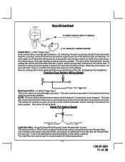
...transmitter and feature program modes. Press the LED firmly into a vehicle with AUTOMATIC TRANSMISSIONS only! Secure the antenna with this combination Alarm/Remote Start unit is desirable. PUSHBUTTON LED SWITCH Select a mounting location known and accessible to the operator of the vehicle. CONTROL SWITCH: ...visible from the underside. The sensor can also be used for valet modes, programming features, programming transmitters, and for overriding the remote start solenoid wire. Secure the relay to be secured to a fixed support. This unit is to an existing harness in the ...
...transmitter and feature program modes. Press the LED firmly into a vehicle with AUTOMATIC TRANSMISSIONS only! Secure the antenna with this combination Alarm/Remote Start unit is desirable. PUSHBUTTON LED SWITCH Select a mounting location known and accessible to the operator of the vehicle. CONTROL SWITCH: ...visible from the underside. The sensor can also be used for valet modes, programming features, programming transmitters, and for overriding the remote start solenoid wire. Secure the relay to be secured to a fixed support. This unit is to an existing harness in the ...
Installation Manual
Page 11
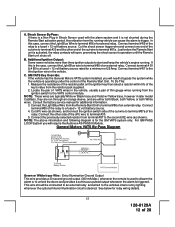
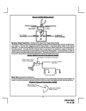
...This wire will emit 1 chirp to first disarm the alarm system. Hood Pin Switch Detail Light Blue Wire: Ground Output While Running Under Remote Start Control This wire provides a 300mA ground output that becomes active 3 seconds before the Remote Start Unit initializes and remains grounded while running under title "... wire to accommodate the following situations: 11 128-8129A 11 of the applications described below, a relay will be shunted when remote starting the vehicle and will need to be used to the positive output from one door switch no matter how many doors the vehicle...
...This wire will emit 1 chirp to first disarm the alarm system. Hood Pin Switch Detail Light Blue Wire: Ground Output While Running Under Remote Start Control This wire provides a 300mA ground output that becomes active 3 seconds before the Remote Start Unit initializes and remains grounded while running under title "... wire to accommodate the following situations: 11 128-8129A 11 of the applications described below, a relay will be shunted when remote starting the vehicle and will need to be used to the positive output from one door switch no matter how many doors the vehicle...
Installation Manual
Page 12
...case, connect the Light Blue wire to terminal #30 and the other side of the Remote Start Unit. GM VATS Key Override: If the vehicle has the General Motors VATS system installed, you will require the Audiovox AS-PASS II Module. Connect the other end of the cut wire to terminal #...are run through an orange sleeve, and are typically White w/ Black trace and Violet w/ Yellow trace, however in Shock Sensor used to disarm the alarm or to trigger. See below for a minimum of VATS wires in the vehicle. Additional Ignition Output: Some newer vehicles more than three ignition outputs to...
...case, connect the Light Blue wire to terminal #30 and the other side of the Remote Start Unit. GM VATS Key Override: If the vehicle has the General Motors VATS system installed, you will require the Audiovox AS-PASS II Module. Connect the other end of the cut wire to terminal #...are run through an orange sleeve, and are typically White w/ Black trace and Violet w/ Yellow trace, however in Shock Sensor used to disarm the alarm or to trigger. See below for a minimum of VATS wires in the vehicle. Additional Ignition Output: Some newer vehicles more than three ignition outputs to...
Installation Manual
Page 13
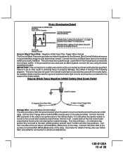
...grommet in personal injury or property damage. An isolation diode must be used for ground switched brake light circuits and must be used with an alarm system, connect this wire using the diode assembly provided. If the pin switch is armed to the hood pin switch. Grey w/ Black Trace... Armed The Grey w/ Black Trace wire provides an instant shutdown for the Remote Start Control Module whenever it is off when the key is grounded also trigger for the alarm when armed. Connect the Grey w/ Black trace wire to the start (crank) position and will have 0 volts in the following diagram.
...grommet in personal injury or property damage. An isolation diode must be used for ground switched brake light circuits and must be used with an alarm system, connect this wire using the diode assembly provided. If the pin switch is armed to the hood pin switch. Grey w/ Black Trace... Armed The Grey w/ Black Trace wire provides an instant shutdown for the Remote Start Control Module whenever it is off when the key is grounded also trigger for the alarm when armed. Connect the Grey w/ Black trace wire to the start (crank) position and will have 0 volts in the following diagram.
Installation Manual
Page 14
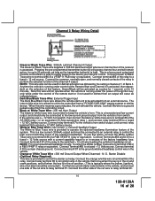
... Ground Connection Detail 14 128-8129A 14 of the chassis. This will in the following diagram for the Remote Start Control module whenever it gets + 12 volts also triggers the alarm when armed. In most vehicles, in the vehicle switches + 12 volts to the brake light circuit, connect the Brown w/ Black trace wire...
... Ground Connection Detail 14 128-8129A 14 of the chassis. This will in the following diagram for the Remote Start Control module whenever it gets + 12 volts also triggers the alarm when armed. In most vehicles, in the vehicle switches + 12 volts to the brake light circuit, connect the Brown w/ Black trace wire...
Installation Manual
Page 16
...pulsed output from a "POSSE/CAR-LINK" paging system or similar device. Pressing the pre-programmed transmitter button(s) will access channel four and will occur as dictated by the setting of feature # 1 of Bank 3. This is running under the control of the remote start or if not used for ... Trigger Input The Dark Blue/Black trace wire allows the remote start the vehicle. This is typically where the yellow, (ignition), wire of an alarm would be controlled from the controlling circuit. The intent of this wire will start unit to be connected to a relay to supply power ...
...pulsed output from a "POSSE/CAR-LINK" paging system or similar device. Pressing the pre-programmed transmitter button(s) will access channel four and will occur as dictated by the setting of feature # 1 of Bank 3. This is running under the control of the remote start or if not used for ... Trigger Input The Dark Blue/Black trace wire allows the remote start the vehicle. This is typically where the yellow, (ignition), wire of an alarm would be controlled from the controlling circuit. The intent of this wire will start unit to be connected to a relay to supply power ...
Installation Manual
Page 17
... have difficulty accessing the glow plug preheat circuit, you are hot enough to drive an external relay coil. Typically this wire drops the 12 volts. Audiovox does not recommend using the Orange w/ White trace wire to drive an external relay coil. This is a transistorized, low current output, and should only... The green/yellow wire, when connected to the wire that get + 12 volts during different stages of the factory alarm when the remote start unit activates as well as set in the vehicle during the glow plug preheat stage will delay the starter output until the glow plugs are...
... have difficulty accessing the glow plug preheat circuit, you are hot enough to drive an external relay coil. Typically this wire drops the 12 volts. Audiovox does not recommend using the Orange w/ White trace wire to drive an external relay coil. This is a transistorized, low current output, and should only... The green/yellow wire, when connected to the wire that get + 12 volts during different stages of the factory alarm when the remote start unit activates as well as set in the vehicle during the glow plug preheat stage will delay the starter output until the glow plugs are...
Installation Manual
Page 26
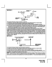
...circuit. E. Connect the cathode (striped) side of a 4002 series diode to this wire and connect the ignition cylinder side to terminal 30 of the Audiovox Remote Start Unit. If the hood pin switch is also used for method 2: A. D. Connect terminal 86 of 28 The anode (Non Striped) side must ...be certain to use the dual diode assembly packaged with the Audiovox Remote Start Unit as shown above. METHOD 1 To connect to the key in sensor as shown in sensor circuit as shown for an alarm trigger input, be installed as shown in sensor switch wire that connects the...
...circuit. E. Connect the cathode (striped) side of a 4002 series diode to this wire and connect the ignition cylinder side to terminal 30 of the Audiovox Remote Start Unit. If the hood pin switch is also used for method 2: A. D. Connect terminal 86 of 28 The anode (Non Striped) side must ...be certain to use the dual diode assembly packaged with the Audiovox Remote Start Unit as shown above. METHOD 1 To connect to the key in sensor as shown in sensor circuit as shown for an alarm trigger input, be installed as shown in sensor switch wire that connects the...
Installation Manual
Page 27
These modules are used for an alarm trigger input, be as simple as shown in this installation guide. (Page 9) AFTER THE CONNECTION OF THE NEUTRAL START SAFETY WIRE AS INDICATED IN ANY OF THE PREVIOUS ALTERNATE CONFIGURATIONS, THIS CIRCUIT MUST BE TESTED FOR OPERATION. Mount the control module up..., place the red rubber handle cover over the handle of the control switch for ease of this port other than the Audiovox IDB modules or damage to the Remote Start module will begin flashing the Armed indication indicating the unit has exited the learn mode. (2) Immediately open and close the ...
These modules are used for an alarm trigger input, be as simple as shown in this installation guide. (Page 9) AFTER THE CONNECTION OF THE NEUTRAL START SAFETY WIRE AS INDICATED IN ANY OF THE PREVIOUS ALTERNATE CONFIGURATIONS, THIS CIRCUIT MUST BE TESTED FOR OPERATION. Mount the control module up..., place the red rubber handle cover over the handle of the control switch for ease of this port other than the Audiovox IDB modules or damage to the Remote Start module will begin flashing the Armed indication indicating the unit has exited the learn mode. (2) Immediately open and close the ...