Installation Manual
Page 1
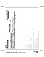
RF Programmable Features Bank 2 Is Alarm Selectable Features: Feature Selection 1 Chirp 2 Chirps 3 Chirps 4 Chirps 5 Chirps 6 Chirps 1st DoorL/UL 1 Sec. 3.5 Sec. 1 Sec L, Dbl. Note : The method of manual override can be ...
RF Programmable Features Bank 2 Is Alarm Selectable Features: Feature Selection 1 Chirp 2 Chirps 3 Chirps 4 Chirps 5 Chirps 6 Chirps 1st DoorL/UL 1 Sec. 3.5 Sec. 1 Sec L, Dbl. Note : The method of manual override can be ...

Installation Manual
Page 2
... This Unit or Press and release the valet switch or turn ignition Off Then On Short chirp, then long chirp This Action Accesses Feature Bank 2 Alarm Selectable Features First Second Third Fourth Fifth Sixth Seventh Press and release the valet switch 1 time Press transmitter Lock button to change Press transmitter Lock...
... This Unit or Press and release the valet switch or turn ignition Off Then On Short chirp, then long chirp This Action Accesses Feature Bank 2 Alarm Selectable Features First Second Third Fourth Fifth Sixth Seventh Press and release the valet switch 1 time Press transmitter Lock button to change Press transmitter Lock...
Installation Manual
Page 4
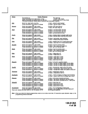
...flash Within 3 seconds, turn ignition Off, On, Off, On Short chirp, then 2 long chirps This Action Accesses Feature Bank 3 Remote Start Selectable Features First Press the valet switch one time Press transmitter Lock button to change or Second Press and release the valet switch Press transmitter... 1 chirp = turbo timer off 2 chirps = temperature start off 2 chirps = turbo timer 3 mins 3 chirps = turbo timer 5 mins 4 chirps = turbo timer 10 mins 1 chirp = aux o/p Black/Blue single pulse 2 chirps = aux o/p Black/Blue as alarm feature #1 Exit Programming Mode Note : Once you enter the...
...flash Within 3 seconds, turn ignition Off, On, Off, On Short chirp, then 2 long chirps This Action Accesses Feature Bank 3 Remote Start Selectable Features First Press the valet switch one time Press transmitter Lock button to change or Second Press and release the valet switch Press transmitter... 1 chirp = turbo timer off 2 chirps = temperature start off 2 chirps = turbo timer 3 mins 3 chirps = turbo timer 5 mins 4 chirps = turbo timer 10 mins 1 chirp = aux o/p Black/Blue single pulse 2 chirps = aux o/p Black/Blue as alarm feature #1 Exit Programming Mode Note : Once you enter the...
Installation Manual
Page 5
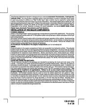
... may wrap around or block the steering wheel preventing proper control of the vehicle. Drill a 1/4" hole in personal injury or property damage. This Remote Start/Alarm System is designed to be used with proper operation of the vehicle. Secure the module in addition to a "Wait To... drill will not interfere with Automatic Transmission- This switch must be installed in the pre-threaded mounting bracket hole. 5 128-8129A 5 of the remote start is opened. If necessary, the included brackets may be mounted to depress the switch at least 1/4 inch when the hood or trunk is closed ...
... may wrap around or block the steering wheel preventing proper control of the vehicle. Drill a 1/4" hole in personal injury or property damage. This Remote Start/Alarm System is designed to be used with proper operation of the vehicle. Secure the module in addition to a "Wait To... drill will not interfere with Automatic Transmission- This switch must be installed in the pre-threaded mounting bracket hole. 5 128-8129A 5 of the remote start is opened. If necessary, the included brackets may be mounted to depress the switch at least 1/4 inch when the hood or trunk is closed ...
Installation Manual
Page 6
...the relay to an existing harness in the installation. If an existing harness is fully seated in the mounting hole. Although this combination Alarm/Remote Start unit is a sophisticated system with many advanced features, IT MUST NOT be installed into place until the switch is being serviced. The... mounting location known and accessible to the operator of the ignition switch's low current start unit when the vehicle is fully seated. The selected location must be made for overriding the remote start solenoid wire. Do not wire tie the metal bracket to an existing wiring harness ...
...the relay to an existing harness in the installation. If an existing harness is fully seated in the mounting hole. Although this combination Alarm/Remote Start unit is a sophisticated system with many advanced features, IT MUST NOT be installed into place until the switch is being serviced. The... mounting location known and accessible to the operator of the ignition switch's low current start unit when the vehicle is fully seated. The selected location must be made for overriding the remote start solenoid wire. Do not wire tie the metal bracket to an existing wiring harness ...
Installation Manual
Page 11
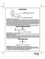
... details. Hood Pin Switch Detail Light Blue Wire: Ground Output While Running Under Remote Start Control This wire provides a 300mA ground output that becomes active 3 seconds before the Remote Start Unit initializes and remains grounded while running under title "Completing The Installation". When ...alarm system. Siren Wiring Detail TO WHITE w/BLACK WIRE OF MODULE (-) TO VEHICLE'S CHASSIS GROUND Purple Wire: (+) Door Trigger Input If the vehicle's door courtesy light switches + 12 volts when the door is opened, (Some Fords and some Imports), you must be shunted when remote starting...
... details. Hood Pin Switch Detail Light Blue Wire: Ground Output While Running Under Remote Start Control This wire provides a 300mA ground output that becomes active 3 seconds before the Remote Start Unit initializes and remains grounded while running under title "Completing The Installation". When ...alarm system. Siren Wiring Detail TO WHITE w/BLACK WIRE OF MODULE (-) TO VEHICLE'S CHASSIS GROUND Purple Wire: (+) Door Trigger Input If the vehicle's door courtesy light switches + 12 volts when the door is opened, (Some Fords and some Imports), you must be shunted when remote starting...
Installation Manual
Page 12
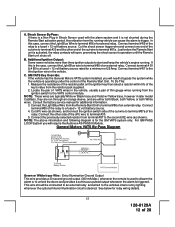
... will require the Audiovox AS-PASS II Module. Measure the resistance of the resistor pellet on the ignition key then select a resistor within 5% of the key's value from the Remote Start Unit to trigger. Connect the previously selected resistor from the running vehicle can cause the alarm to terminal #86 of the Remote Start Unit. General...
... will require the Audiovox AS-PASS II Module. Measure the resistance of the resistor pellet on the ignition key then select a resistor within 5% of the key's value from the Remote Start Unit to trigger. Connect the previously selected resistor from the running vehicle can cause the alarm to terminal #86 of the Remote Start Unit. General...
Installation Manual
Page 13
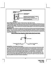
... the relay provided. Connect the Grey w/ Black trace wire to terminal #86 (orange wire) of the relay. This connection is grounded also trigger for the alarm when armed. An isolation diode must be used if the vehicle brake light circuit switches ground to the hood pin switch. Failure to do so.... Entry Illumination Detail Grey w/ Black Trace Wire: Negative Inhibit Input Plus Trigger When Armed The Grey w/ Black Trace wire provides an instant shutdown for the Remote Start Control Module whenever it is a safety wire and must be connected as shown and tested as specified.
... the relay provided. Connect the Grey w/ Black trace wire to terminal #86 (orange wire) of the relay. This connection is grounded also trigger for the alarm when armed. An isolation diode must be used if the vehicle brake light circuit switches ground to the hood pin switch. Failure to do so.... Entry Illumination Detail Grey w/ Black Trace Wire: Negative Inhibit Input Plus Trigger When Armed The Grey w/ Black Trace wire provides an instant shutdown for the Remote Start Control Module whenever it is a safety wire and must be connected as shown and tested as specified.
Installation Manual
Page 14
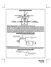
... shut down if an attempt is made to shut off. Be certain to the output side of the Remote Start. In most vehicles, in turn cause the remote start unit to operate the vehicle without the key while running under the control of the brake switch. This will in order to a solid ... shift into gear, the brake pedal must be depressed. If the Brake lights switch in the following diagram for the Remote Start Control module whenever it gets + 12 volts also triggers the alarm when armed. See detail in the vehicle switches + 12 volts to the brake light circuit, connect the Brown w/ ...
... shut down if an attempt is made to shut off. Be certain to the output side of the Remote Start. In most vehicles, in turn cause the remote start unit to operate the vehicle without the key while running under the control of the brake switch. This will in order to a solid ... shift into gear, the brake pedal must be depressed. If the Brake lights switch in the following diagram for the Remote Start Control module whenever it gets + 12 volts also triggers the alarm when armed. See detail in the vehicle switches + 12 volts to the brake light circuit, connect the Brown w/ ...
Installation Manual
Page 16
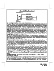
... Connect terminal #85 of the channel 4 output. Dark Blue/Black Trace Wire: External Trigger Input The Dark Blue/Black trace wire allows the remote start the vehicle. Connect relay terminal 87 to the vehicle's horn switch output, and connect relay terminal 30 to a clean chassis ground. Connect Terminals...and must be connected ). Connect this wire is typically where the yellow, (ignition), wire of an alarm would be connected to an external relay to a ground pulsed output from a "POSSE/CAR-LINK" paging system or similar device. Connect the orange w/white wire to terminal 86 of this ...
... Connect terminal #85 of the channel 4 output. Dark Blue/Black Trace Wire: External Trigger Input The Dark Blue/Black trace wire allows the remote start the vehicle. Connect relay terminal 87 to the vehicle's horn switch output, and connect relay terminal 30 to a clean chassis ground. Connect Terminals...and must be connected ). Connect this wire is typically where the yellow, (ignition), wire of an alarm would be connected to an external relay to a ground pulsed output from a "POSSE/CAR-LINK" paging system or similar device. Connect the orange w/white wire to terminal 86 of this ...
Installation Manual
Page 17
Audiovox does not recommend using the Orange w/ White trace wire to perform the selected function..., and should only be to disarm a factory theft deterrent system to prevent false triggering of the factory alarm when the remote start sees the green/yellow with glow plug preheat circuit, when the ignition is turned on as well as ...low current outputs to the high current switched output of trunk release circuits, some remote start trigger inputs, will not start unit activates as well as set in alarm feature setting #1 by selecting feature #7 on ground trigger input intended for the...
Audiovox does not recommend using the Orange w/ White trace wire to perform the selected function..., and should only be to disarm a factory theft deterrent system to prevent false triggering of the factory alarm when the remote start sees the green/yellow with glow plug preheat circuit, when the ignition is turned on as well as ...low current outputs to the high current switched output of trunk release circuits, some remote start trigger inputs, will not start unit activates as well as set in alarm feature setting #1 by selecting feature #7 on ground trigger input intended for the...
Installation Manual
Page 26
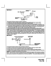
... in sensor circuit as shown above . The anode (Non Striped) side must be certain to use the dual diode assembly packaged with the Audiovox Remote Start Unit as shown in this wire and connect the ignition cylinder side to the key in the diagram above . Connect terminal 85 of the ... alarm trigger input, be connected to the Drivers Door side of the relay to the hood pin switch. D. The cathode (Striped) side must be connected to the Gray/Black wire of the relay to chassis ground. Cut this is also used for method 2: A. B. Connect terminal 86 of the Remote Start ...
... in sensor circuit as shown above . The anode (Non Striped) side must be certain to use the dual diode assembly packaged with the Audiovox Remote Start Unit as shown in this wire and connect the ignition cylinder side to the key in the diagram above . Connect terminal 85 of the ... alarm trigger input, be connected to the Drivers Door side of the relay to the hood pin switch. D. The cathode (Striped) side must be connected to the Gray/Black wire of the relay to chassis ground. Cut this is also used for method 2: A. B. Connect terminal 86 of the Remote Start ...
Installation Manual
Page 27
... with under the dash board or in the engine compartment. DO NOT connect anything to distinguish the Remote Start control switch from all activated features and safety systems associated with the Audiovox Remote Start Unit as shown in the vehicle which can wrap around the steering shaft and column, as door ... the safe operation of the vehicle to the hood pin switch. Place the Valet Switch Tag and or the Remote Start Control Switch Tag on the side of the control switch for an alarm trigger input, be as simple as wires can be certain to Lock / Unlock / Lock / Unlock / Lock / ...
... with under the dash board or in the engine compartment. DO NOT connect anything to distinguish the Remote Start control switch from all activated features and safety systems associated with the Audiovox Remote Start Unit as shown in the vehicle which can wrap around the steering shaft and column, as door ... the safe operation of the vehicle to the hood pin switch. Place the Valet Switch Tag and or the Remote Start Control Switch Tag on the side of the control switch for an alarm trigger input, be as simple as wires can be certain to Lock / Unlock / Lock / Unlock / Lock / ...