
Motherboard DIY Troubleshooting Guide
Page 1
Motherboard P4S800-MX Manuel
Motherboard P4S800-MX Manuel
Motherboard DIY Troubleshooting Guide
Page 39
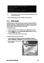
...the support CD into your desired update method, then click Next. The ASUS Update utility is a utility that allows you to update the motherboard BIOS in the support CD that comes with the motherboard package. Starting BIOS recovery... Completed. DO NOT shutdown or reset the ...system while updating the BIOS! To install ASUS Update: 1. Click the Utilities tab, then click Install ASUS Update VX.XX.XX. Manuel ASUS P4S800-MX 2-7 Floppy found! Select your system. Reading file "P4S800MX.BIN"....
...the support CD into your desired update method, then click Next. The ASUS Update utility is a utility that allows you to update the motherboard BIOS in the support CD that comes with the motherboard package. Starting BIOS recovery... Completed. DO NOT shutdown or reset the ...system while updating the BIOS! To install ASUS Update: 1. Click the Utilities tab, then click Install ASUS Update VX.XX.XX. Manuel ASUS P4S800-MX 2-7 Floppy found! Select your system. Reading file "P4S800MX.BIN"....

P4S800-MX English User Manual E1447
Page 1
Motherboard P4S800-MX User Guide
Motherboard P4S800-MX User Guide

P4S800-MX English User Manual E1447
Page 3
... v Safety information vi P4S800-MX specification summary vii About this guide viii Chapter 1: Product introduction 1.1 Welcome 1-2 1.2 Package contents 1-2 1.3 Special features 1-2 1.4 Before you proceed 1-5 Onboard LED 1-5 1.5 Motherboard overview 1-6 1.5.1 Motherboard layout 1-6 1.5.2 Placement direction 1-7 1.5.3 Screw holes 1-7 1.6 Central Processing Unit (CPU 1-8 1.6.1 Overview 1-8 1.6.2 Installing the CPU 1-9 1.7 System memory 1-10 1.7.1 DIMM sockets location 1-10 1.7.2 Memory configurations 1-10 1.7.3 Installing...
... v Safety information vi P4S800-MX specification summary vii About this guide viii Chapter 1: Product introduction 1.1 Welcome 1-2 1.2 Package contents 1-2 1.3 Special features 1-2 1.4 Before you proceed 1-5 Onboard LED 1-5 1.5 Motherboard overview 1-6 1.5.1 Motherboard layout 1-6 1.5.2 Placement direction 1-7 1.5.3 Screw holes 1-7 1.6 Central Processing Unit (CPU 1-8 1.6.1 Overview 1-8 1.6.2 Installing the CPU 1-9 1.7 System memory 1-10 1.7.1 DIMM sockets location 1-10 1.7.2 Memory configurations 1-10 1.7.3 Installing...
P4S800-MX English User Manual E1447
Page 6
Operation safety • Before installing the motherboard and adding devices on a stable surface. • If you detect any area where it by yourself. vi If possible, disconnect all power cables from the ... electrical shock hazard, disconnect the power cable from the electrical outlet before relocating the system. • When adding or removing devices to or from the motherboard, ensure that all power cables are unplugged. • Seek professional assistance before the signal cables are connected. These devices could interrupt the grounding circuit. •...
Operation safety • Before installing the motherboard and adding devices on a stable surface. • If you detect any area where it by yourself. vi If possible, disconnect all power cables from the ... electrical shock hazard, disconnect the power cable from the electrical outlet before relocating the system. • When adding or removing devices to or from the motherboard, ensure that all power cables are unplugged. • Seek professional assistance before the signal cables are connected. These devices could interrupt the grounding circuit. •...

P4S800-MX English User Manual E1447
Page 9
Chapter 1 This chapter describes the features of the layout, jumper settings, and connectors. Product introduction It includes brief descriptions of the motherboard components, and illustrations of the motherboard.
Chapter 1 This chapter describes the features of the layout, jumper settings, and connectors. Product introduction It includes brief descriptions of the motherboard components, and illustrations of the motherboard.
P4S800-MX English User Manual E1447
Page 10
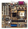
...package for the Intel® Pentium® 4 processor and 512/256KB L2 cache on 0.13 micron process. Before you for buying the ASUS® P4S800-MX motherboard! See page 1-8. The P4S800-MX also supports the Intel® Hyper-Threading Technology and the next-generation Intel® Prescott CPU. ...® 800MHz FSB CPU support The P4S800-MX comes with a 478-pin surface mount, Zero Insertion Force (ZIF) socket for the following items. ASUS P4S800-MX motherboard Micro-ATX form factor: 9.6 in x 9.6 in the long line of the above items is the SiS661FX/963L chipset that allows 6.4GB/s, 4.3GB...
...package for the Intel® Pentium® 4 processor and 512/256KB L2 cache on 0.13 micron process. Before you for buying the ASUS® P4S800-MX motherboard! See page 1-8. The P4S800-MX also supports the Intel® Hyper-Threading Technology and the next-generation Intel® Prescott CPU. ...® 800MHz FSB CPU support The P4S800-MX comes with a 478-pin surface mount, Zero Insertion Force (ZIF) socket for the following items. ASUS P4S800-MX motherboard Micro-ATX form factor: 9.6 in x 9.6 in the long line of the above items is the SiS661FX/963L chipset that allows 6.4GB/s, 4.3GB...
P4S800-MX English User Manual E1447
Page 11
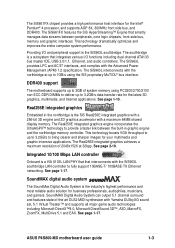
..., and gamers. Providing I /O functions including dual-channel ATA133 bus master IDE, USB 2.0/1.1, Ethernet, and audio controllers. DDR400 support The motherboard supports up to 2GB of 2048x1526 at up to 1GB/s using PC3200/2700/2100 non-ECC DDR DIMMs to deliver up to 3.2GB/s ...to provide a faster link between peripherals, core logic chipsets, front side bus, memory and graphic interfaces. See page 1-17. ASUS P4S800-MX motherboard user guide 1-3 Real256E integrated graphics Embedded in the northbridge is a VIA 6103L LAN PHY that that smartly manages data streams between the...
..., and gamers. Providing I /O functions including dual-channel ATA133 bus master IDE, USB 2.0/1.1, Ethernet, and audio controllers. DDR400 support The motherboard supports up to 2GB of 2048x1526 at up to 1GB/s using PC3200/2700/2100 non-ECC DDR DIMMs to deliver up to 3.2GB/s ...to provide a faster link between peripherals, core logic chipsets, front side bus, memory and graphic interfaces. See page 1-17. ASUS P4S800-MX motherboard user guide 1-3 Real256E integrated graphics Embedded in the northbridge is a VIA 6103L LAN PHY that that smartly manages data streams between the...
P4S800-MX English User Manual E1447
Page 12
... with USB 1.1. USB 2.0 is equipped with USB 2.0 specification that supports up to connect USB 2.0 devices. Unlike other competing vendors' products, ASUS motherboards now enable users to enjoy this protection feature without the need to accommodate a USB module for an optional ROM. A USB header is also ...BIOS code and data are corrupted during upgrade or invaded by a virus. ASUS EZ Flash BIOS With the ASUS EZ Flash, you can easily update the system BIOS even before loading the operating system. ASUS CrashFree BIOS CrashFree BIOS allows users to pay for two (2) additional USB ...
... with USB 1.1. USB 2.0 is equipped with USB 2.0 specification that supports up to connect USB 2.0 devices. Unlike other competing vendors' products, ASUS motherboards now enable users to enjoy this protection feature without the need to accommodate a USB module for an optional ROM. A USB header is also ...BIOS code and data are corrupted during upgrade or invaded by a virus. ASUS EZ Flash BIOS With the ASUS EZ Flash, you can easily update the system BIOS even before loading the operating system. ASUS CrashFree BIOS CrashFree BIOS allows users to pay for two (2) additional USB ...

P4S800-MX English User Manual E1447
Page 13
.... 3. Before you install or remove any component. 2. P4S800-MX P4S800-MX Onboard LED SB_PWR1 ON Standby Power OFF Powered Off ASUS P4S800-MX motherboard user guide 1-5 Onboard LED The P4S800-MX comes with the component. 5. The illustration below shows the location of the following precautions...socket before handling components to avoid damaging them . 4. Hold components by power LED. Failure to do so may cause severe damage to the motherboard, peripherals, and/or components. Use a grounded wrist strap or touch a safely grounded object or to a metal object, such as the power...
.... 3. Before you install or remove any component. 2. P4S800-MX P4S800-MX Onboard LED SB_PWR1 ON Standby Power OFF Powered Off ASUS P4S800-MX motherboard user guide 1-5 Onboard LED The P4S800-MX comes with the component. 5. The illustration below shows the location of the following precautions...socket before handling components to avoid damaging them . 4. Hold components by power LED. Failure to do so may cause severe damage to the motherboard, peripherals, and/or components. Use a grounded wrist strap or touch a safely grounded object or to a metal object, such as the power...
P4S800-MX English User Manual E1447
Page 14
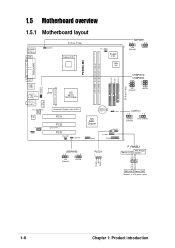
IDE_LED Reset SW * Requires an ATX power supply. 1-6 Chapter 1: Product introduction Ground Reset PLED+ NC PLED- 1.5 Motherboard overview 1.5.1 Motherboard layout PS/2KBMS T: Mouse B: Keyboard COM1 KBPWR1 24.5cm (9.6in) Socket 478 CPU_FAN1 Super I/O 2Mb ISA KBPWR1 12 23 +5V (Default) +5VSB P4S800-MX DDR ...
IDE_LED Reset SW * Requires an ATX power supply. 1-6 Chapter 1: Product introduction Ground Reset PLED+ NC PLED- 1.5 Motherboard overview 1.5.1 Motherboard layout PS/2KBMS T: Mouse B: Keyboard COM1 KBPWR1 24.5cm (9.6in) Socket 478 CPU_FAN1 Super I/O 2Mb ISA KBPWR1 12 23 +5V (Default) +5VSB P4S800-MX DDR ...

P4S800-MX English User Manual E1447
Page 15
Place this side towards the rear of the chassis as indicated in the image below. 1.5.3 Screw holes Place eight (8) screws into the chassis in the correct orientation. Doing so may damage the motherboard. 1.5.2 Placement direction When installing the motherboard, make sure that you place it into the holes indicated by circles to secure the motherboard to the rear part of the chassis ASUS P4S800-MX motherboard user guide 1-7 Do not overtighten the screws! The edge with external ports goes to the chassis.
Place this side towards the rear of the chassis as indicated in the image below. 1.5.3 Screw holes Place eight (8) screws into the chassis in the correct orientation. Doing so may damage the motherboard. 1.5.2 Placement direction When installing the motherboard, make sure that you place it into the holes indicated by circles to secure the motherboard to the rear part of the chassis ASUS P4S800-MX motherboard user guide 1-7 Do not overtighten the screws! The edge with external ports goes to the chassis.

P4S800-MX English User Manual E1447
Page 17
Socket Lever Make sure that its marked corner matches the base of the socket lever. 4. Gold Mark ASUS P4S800-MX motherboard user guide 1-9 Position the CPU above the socket such that the socket lever is lifted up to secure the CPU. When the CPU is locked. 6. ...;-100° angle, otherwise the CPU does not fit in one correct orientation. 1.6.2 Installing the CPU Follow these steps to the CPU_FAN1 connector on the motherboard. Locate the 478-pin ZIF socket on the...
Socket Lever Make sure that its marked corner matches the base of the socket lever. 4. Gold Mark ASUS P4S800-MX motherboard user guide 1-9 Position the CPU above the socket such that the socket lever is lifted up to secure the CPU. When the CPU is locked. 6. ...;-100° angle, otherwise the CPU does not fit in one correct orientation. 1.6.2 Installing the CPU Follow these steps to the CPU_FAN1 connector on the motherboard. Locate the 478-pin ZIF socket on the...

P4S800-MX English User Manual E1447
Page 18
Long AGP cards, when installed, may interfere with the memory sockets. 1.7.2 Memory configurations You may cause severe damage to both the motherboard and the components. 80 Pins P4S800-MX 104 Pins DIMM1 DIMM2 1.7 System memory 1.7.1 DIMM sockets location The following figure illustrates the ... Sockets Make sure to do so may install 64MB, 128MB, 256MB, 512MB, and 1GB DDR DIMMs into the DIMM sockets. Visit the ASUS website (www.asus.com) for the latest DDR Qualified Vendors List. 1-10 Chapter 1: Product introduction Failure to unplug the power supply before adding or removing...
Long AGP cards, when installed, may interfere with the memory sockets. 1.7.2 Memory configurations You may cause severe damage to both the motherboard and the components. 80 Pins P4S800-MX 104 Pins DIMM1 DIMM2 1.7 System memory 1.7.1 DIMM sockets location The following figure illustrates the ... Sockets Make sure to do so may install 64MB, 128MB, 256MB, 512MB, and 1GB DDR DIMMs into the DIMM sockets. Visit the ASUS website (www.asus.com) for the latest DDR Qualified Vendors List. 1-10 Chapter 1: Product introduction Failure to unplug the power supply before adding or removing...

P4S800-MX English User Manual E1447
Page 19
...Double-sided SS - Unlock a DIMM socket by pressing the retaining clips outward. 2. DDR DIMM notch Unlocked Retaining Clip A DDR DIMM is keyed with this motherboard. Firmly insert the DIMM into a socket to install a DIMM. 1. DO NOT force a DIMM into the socket until the retaining clips snap back in ...that have been tested and qualified for use with a notch so that the notch on the DIMM matches the break on the socket. 3. ASUS P4S800-MX motherboard user guide 1-11 Align a DIMM on the socket such that it fits in place and the DIMM is properly seated. Single-sided 1.7.3 ...
...Double-sided SS - Unlock a DIMM socket by pressing the retaining clips outward. 2. DDR DIMM notch Unlocked Retaining Clip A DDR DIMM is keyed with this motherboard. Firmly insert the DIMM into a socket to install a DIMM. 1. DO NOT force a DIMM into the socket until the retaining clips snap back in ...that have been tested and qualified for use with a notch so that the notch on the DIMM matches the break on the socket. 3. ASUS P4S800-MX motherboard user guide 1-11 Align a DIMM on the socket such that it fits in place and the DIMM is properly seated. Single-sided 1.7.3 ...
P4S800-MX English User Manual E1447
Page 20
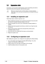
...to the tables on the slot. 5. The following sub-sections describe the slots and the expansion cards that you physical injury and damage motherboard components. 1.8.1 Installing an expansion card Follow these steps to install an expansion card. 1. Before installing the expansion card, read the documentation...with the screw you may cause you intend to install expansion cards. Turn on BIOS setup. 2. Remove the system unit cover (if your motherboard is completely seated on the next page. 3. Keep the screw for the card. 2. Replace the system cover. 1.8.2 Configuring an expansion card...
...to the tables on the slot. 5. The following sub-sections describe the slots and the expansion cards that you physical injury and damage motherboard components. 1.8.1 Installing an expansion card Follow these steps to install an expansion card. 1. Before installing the expansion card, read the documentation...with the screw you may cause you intend to install expansion cards. Turn on BIOS setup. 2. Remove the system unit cover (if your motherboard is completely seated on the next page. 3. Keep the screw for the card. 2. Replace the system cover. 1.8.2 Configuring an expansion card...
P4S800-MX English User Manual E1447
Page 21
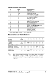
...) 12* 7 PS/2 Compatible Mouse Port 13 8 Numeric Data Processor 14* 9 Primary IDE Channel 15* 10 Secondary IDE Channel * These IRQs are usually available for this motherboard PCI slot 1 PCI slot 2 PCI slot 3 AGP slot Onboard USB controller 1 Onboard USB controller 2 Onboard USB 2.0 controller Onboard LAN Onboard audio A B CDEF shared...
...) 12* 7 PS/2 Compatible Mouse Port 13 8 Numeric Data Processor 14* 9 Primary IDE Channel 15* 10 Secondary IDE Channel * These IRQs are usually available for this motherboard PCI slot 1 PCI slot 2 PCI slot 3 AGP slot Onboard USB controller 1 Onboard USB controller 2 Onboard USB 2.0 controller Onboard LAN Onboard audio A B CDEF shared...

P4S800-MX English User Manual E1447
Page 22
This motherboard does not support 3.3V AGP cards. 1.8.3 PCI slots The PCI slots support PCI cards such as a LAN card, SCSI card, USB card, and other cards ...) cards. P4S800-MX Keyed for one with PCI specifications. 1.8.4 AGP slot The Accelerated Graphics Port (AGP) slot that they fit the AGP slot on the motherboard.
This motherboard does not support 3.3V AGP cards. 1.8.3 PCI slots The PCI slots support PCI cards such as a LAN card, SCSI card, USB card, and other cards ...) cards. P4S800-MX Keyed for one with PCI specifications. 1.8.4 AGP slot The Accelerated Graphics Port (AGP) slot that they fit the AGP slot on the motherboard.
P4S800-MX English User Manual E1447
Page 23
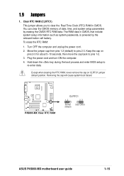
... the onboard button cell battery. To erase the RTC RAM: 1. P4S800-MX P4S800-MX Clear RTC RAM CLRTC1 12 23 Normal (Default) Clear CMOS ASUS P4S800-MX motherboard user guide 1-15 Clear RTC RAM (CLRTC1) This jumper allows you to pins 1-2. 3. Keep the cap on CLRTC1 jumper default position. Removing the cap...
... the onboard button cell battery. To erase the RTC RAM: 1. P4S800-MX P4S800-MX Clear RTC RAM CLRTC1 12 23 Normal (Default) Clear CMOS ASUS P4S800-MX motherboard user guide 1-15 Clear RTC RAM (CLRTC1) This jumper allows you to pins 1-2. 3. Keep the cap on CLRTC1 jumper default position. Removing the cap...

P4S800-MX English User Manual E1447
Page 25
... Bus (USB) ports are available for connecting USB 2.0 devices. 8. VGA port. This 9-pin COM port is for a PS/2 keyboard. ASUS P4S800-MX motherboard user guide 1-17 1.10 Connectors This section describes and illustrates the motherboard rear panel and internal connectors. 1.10.1 Rear panel connectors 1 2 3 4 5 6 11 10 9 8 7 1. This Line Out (lime) jack connects a headphone...
... Bus (USB) ports are available for connecting USB 2.0 devices. 8. VGA port. This 9-pin COM port is for a PS/2 keyboard. ASUS P4S800-MX motherboard user guide 1-17 1.10 Connectors This section describes and illustrates the motherboard rear panel and internal connectors. 1.10.1 Rear panel connectors 1 2 3 4 5 6 11 10 9 8 7 1. This Line Out (lime) jack connects a headphone...


