
Motherboard DIY Troubleshooting Guide
Page 43
Flashed successfully. Floppy found! Completed. User recovery requested. Start flashing... Starting BIOS recovery... Checking for floppy... Reading file "P4P800S.rom". Starting BIOS recovery... Checking for floppy... • • User recovery requested. Rebooting. 2-5
Flashed successfully. Floppy found! Completed. User recovery requested. Start flashing... Starting BIOS recovery... Checking for floppy... Reading file "P4P800S.rom". Starting BIOS recovery... Checking for floppy... • • User recovery requested. Rebooting. 2-5

Motherboard DIY Troubleshooting Guide
Page 44
Start flashing... 2-6 Starting BIOS recovery... Starting BIOS recovery... Checking for floppy... Bad BIOS checksum. Reading file "P4P800S.rom". Completed. Floppy found! Checking for floppy... Bad BIOS checksum.
Start flashing... 2-6 Starting BIOS recovery... Starting BIOS recovery... Checking for floppy... Bad BIOS checksum. Reading file "P4P800S.rom". Completed. Floppy found! Checking for floppy... Bad BIOS checksum.

Motherboard DIY Troubleshooting Guide
Page 45
Bad BIOS checksum. Checking for floppy... Reading file "P4P800S.rom". Completed. Starting BIOS recovery... Checking for floppy... Bad BIOS checksum. CD-ROM found ! Starting BIOS recovery... Checking for CD-ROM... Start flashing... 2-7 Floppy not found .
Bad BIOS checksum. Checking for floppy... Reading file "P4P800S.rom". Completed. Starting BIOS recovery... Checking for floppy... Bad BIOS checksum. CD-ROM found ! Starting BIOS recovery... Checking for CD-ROM... Start flashing... 2-7 Floppy not found .

Motherboard DIY Troubleshooting Guide
Page 53
Change Option F1 General Help F10 Save and Exit ESC Exit 2-15 AMI BIOS Version : 08.00.08 Build Date : 08/01/03 Processor Type Speed Count : Intel(R) Pentium(R) 4 CPU 1.73GHz : 1733 MHz : 1 System Memory Size : 256MB Select Screen Select Item +-
Change Option F1 General Help F10 Save and Exit ESC Exit 2-15 AMI BIOS Version : 08.00.08 Build Date : 08/01/03 Processor Type Speed Count : Intel(R) Pentium(R) 4 CPU 1.73GHz : 1733 MHz : 1 System Memory Size : 256MB Select Screen Select Item +-

Motherboard DIY Troubleshooting Guide
Page 61
...] [64] [Yes] [Disabled] [Enabled] IRQ3 IRQ4 IRQ5 IRQ7 IRQ9 IRQ10 IRQ11 IRQ14 IRQ15 [Available] [Available] [Available] [Available] [Available] [Available] [Available] [Available] [Available] NO: Lets the bIOS configure all the devices in the sections below may cause system to malfunction. Change Option F1 General Help F10 Save and Exit ESC Exit 2-23...
...] [64] [Yes] [Disabled] [Enabled] IRQ3 IRQ4 IRQ5 IRQ7 IRQ9 IRQ10 IRQ11 IRQ14 IRQ15 [Available] [Available] [Available] [Available] [Available] [Available] [Available] [Available] [Available] NO: Lets the bIOS configure all the devices in the sections below may cause system to malfunction. Change Option F1 General Help F10 Save and Exit ESC Exit 2-23...

Motherboard DIY Troubleshooting Guide
Page 65
Suspend Mode Repost Video on S3 Resume ACPI 2.0 Support ACPI APIC Support BIOS -> AML ACPI table APM Configuration Hardware Monitor [Auto] [No] [No] [Enabled] [Enabled] Configure CPU. Select Screen Select Item Enter Go to Sub-screen F1 General Help F10 Save and Exit ESC Exit 2-27
Suspend Mode Repost Video on S3 Resume ACPI 2.0 Support ACPI APIC Support BIOS -> AML ACPI table APM Configuration Hardware Monitor [Auto] [No] [No] [Enabled] [Enabled] Configure CPU. Select Screen Select Item Enter Go to Sub-screen F1 General Help F10 Save and Exit ESC Exit 2-27

Motherboard DIY Troubleshooting Guide
Page 70
.../2 Wait for 'F1' If Error Hit 'DEL' Message Display Interrupt 19 Capture [Enabled] [Enabled] [Force BIOS] [On] [Auto] [Fast] [No] [Enabled] [Enabled] [Disabled] Allows BIOS to boot the system. This will decrease the time needed to skip certain tests while booting. Removable Drives 1st ...Drive 2nd Drive 3rd Drive [1st FLOPPY DRIVE] [PM-ST320413A] [PS-ASUS CD-S340] Specifies the boot sequence from the available devices...
.../2 Wait for 'F1' If Error Hit 'DEL' Message Display Interrupt 19 Capture [Enabled] [Enabled] [Force BIOS] [On] [Auto] [Fast] [No] [Enabled] [Enabled] [Disabled] Allows BIOS to boot the system. This will decrease the time needed to skip certain tests while booting. Removable Drives 1st ...Drive 2nd Drive 3rd Drive [1st FLOPPY DRIVE] [PM-ST320413A] [PS-ASUS CD-S340] Specifies the boot sequence from the available devices...

P4P800S user's manual English version E1398
Page 3
Features Contents Notices v Safety information vi About this guide vii ASUS contact information viii P4P800S specifications summary ix Chapter 1: Product introduction 1.1 Welcome 1-2 1.2 Package contents 1-2 1.3 Special features 1-2 1.4 Motherboard ...12 Connectors 1-21 Chapter 2: BIOS information 2.1 Managing and updating your BIOS 2-2 2.1.1 Creating a bootable floppy disk 2-2 2.1.2 Using AFUDOS to update the BIOS 2-2 2.1.3 Using AFUDOS to copy BIOS from PC 2-4 2.1.4 Using ASUS EZ Flash to update the BIOS 2-5 2.1.5 Recovering the BIOS with CrashFree BIOS 2 ....... 2-6 iii
Features Contents Notices v Safety information vi About this guide vii ASUS contact information viii P4P800S specifications summary ix Chapter 1: Product introduction 1.1 Welcome 1-2 1.2 Package contents 1-2 1.3 Special features 1-2 1.4 Motherboard ...12 Connectors 1-21 Chapter 2: BIOS information 2.1 Managing and updating your BIOS 2-2 2.1.1 Creating a bootable floppy disk 2-2 2.1.2 Using AFUDOS to update the BIOS 2-2 2.1.3 Using AFUDOS to copy BIOS from PC 2-4 2.1.4 Using ASUS EZ Flash to update the BIOS 2-5 2.1.5 Recovering the BIOS with CrashFree BIOS 2 ....... 2-6 iii

P4P800S user's manual English version E1398
Page 4
Safeguards Contents 2.2 BIOS Setup program 2-8 2.2.1 BIOS menu screen 2-9 2.2.2 Menu bar 2-9 2.2.3 Navigation keys 2-9 2.2.4 Menu items 2-10 2.2.5 Sub-menu items 2-10 2.2.6 Configuration fields 2-10 2.2.7 Pop-up window 2-10 2.2.8 ...Power menu 2-27 2.5.1 Suspend Mode [Auto 2-27 2.5.2 Repost Video on S3 Resume [No 2-27 2.5.3 ACPI 2.0 Support [No 2-27 2.5.4 ACPI APIC Support [Enabled 2-27 2.5.5 BIOS -> AML ACPI Table [Enabled 2-27 2.5.6 APM Configuration 2-28 2.5.7 Hardware Monitor 2-30 2.6 Boot menu 2-31 2.6.1 Boot Device Priority 2-31 2.6.2 Removable Drives 2-32 2.6.3 Boot ...
Safeguards Contents 2.2 BIOS Setup program 2-8 2.2.1 BIOS menu screen 2-9 2.2.2 Menu bar 2-9 2.2.3 Navigation keys 2-9 2.2.4 Menu items 2-10 2.2.5 Sub-menu items 2-10 2.2.6 Configuration fields 2-10 2.2.7 Pop-up window 2-10 2.2.8 ...Power menu 2-27 2.5.1 Suspend Mode [Auto 2-27 2.5.2 Repost Video on S3 Resume [No 2-27 2.5.3 ACPI 2.0 Support [No 2-27 2.5.4 ACPI APIC Support [Enabled 2-27 2.5.5 BIOS -> AML ACPI Table [Enabled 2-27 2.5.6 APM Configuration 2-28 2.5.7 Hardware Monitor 2-30 2.6 Boot menu 2-31 2.6.1 Boot Device Priority 2-31 2.6.2 Removable Drives 2-32 2.6.3 Boot ...

P4P800S user's manual English version E1398
Page 9
P4P800S specifications summary CPU Socket 478 for Intel® Pentium®...memory Supports PC3200/PC2700/PC2100 unbuffered non-ECC DDR DIMMs Expansion slots 1 x AGP 8X/4X 5 x PCI 1 x ASUS Wi-Fi slot Storage 2 x UltraDMA 100/66/33 connectors 2 x Serial ATA connectors Audio ADI AD1888 SoundMAX 6-channel ... Fast Ethernet controller Special features Support S/PDIF out interface ASUS MyLogo2 ASUS EZ Flash ASUS C.P.R. (CPU Parameter Recall) ASUS Instant Music-Lite ASUS CrashFree BIOS 2 Extreme Overclocking AI Overclocking ASUS JumperFree CPU, Memory and AGP voltage adjustable SFS (Stepless...
P4P800S specifications summary CPU Socket 478 for Intel® Pentium®...memory Supports PC3200/PC2700/PC2100 unbuffered non-ECC DDR DIMMs Expansion slots 1 x AGP 8X/4X 5 x PCI 1 x ASUS Wi-Fi slot Storage 2 x UltraDMA 100/66/33 connectors 2 x Serial ATA connectors Audio ADI AD1888 SoundMAX 6-channel ... Fast Ethernet controller Special features Support S/PDIF out interface ASUS MyLogo2 ASUS EZ Flash ASUS C.P.R. (CPU Parameter Recall) ASUS Instant Music-Lite ASUS CrashFree BIOS 2 Extreme Overclocking AI Overclocking ASUS JumperFree CPU, Memory and AGP voltage adjustable SFS (Stepless...

P4P800S user's manual English version E1398
Page 10
x P4P800S specifications summary Internal I/O BIOS features Industry standard Manageability Power Requirement Form Factor Support CD contents 2 x USB 2.0 connector for 4 additional USB ports CPU/Chassis fan connectors 20-pin/4-pin ATX ... connectors CD/AUX/MODEM connectors Game/MIDI port connector 20-pin panel connector Front panel audio connector 4Mb Flash ROM, AMI BIOS, ACPI, PnP, DMI2.0, WfM 2.0, SM BIOS 2.3, DMI 2.0, ASUS CrashFree BIOS 2, ASUS EZ Flash, ASUS MyLogo2 PCI 2.3, USB 2.0/1.1 DMI 2.0, WOL/WOR by PME, SMBus ATX power supply (with 4-pin 12V plug) ATX form factor: 12...
x P4P800S specifications summary Internal I/O BIOS features Industry standard Manageability Power Requirement Form Factor Support CD contents 2 x USB 2.0 connector for 4 additional USB ports CPU/Chassis fan connectors 20-pin/4-pin ATX ... connectors CD/AUX/MODEM connectors Game/MIDI port connector 20-pin panel connector Front panel audio connector 4Mb Flash ROM, AMI BIOS, ACPI, PnP, DMI2.0, WfM 2.0, SM BIOS 2.3, DMI 2.0, ASUS CrashFree BIOS 2, ASUS EZ Flash, ASUS MyLogo2 PCI 2.3, USB 2.0/1.1 DMI 2.0, WOL/WOR by PME, SMBus ATX power supply (with 4-pin 12V plug) ATX form factor: 12...
P4P800S user's manual English version E1398
Page 14
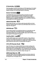
... loading the operating system. Extreme Overclocking The P4P800S offers robust overclocking options to set the BIOS items for an optional ROM. See pages 2-26, 3-5. 1-4 Chapter 1: Product introduction See page 2-16 to maximize your system with a fixed AGP/PCI frequency and the ASUS C.P.R. (CPU Parameter Recall). ASUS Instant Music Lite This unique feature allows you...
... loading the operating system. Extreme Overclocking The P4P800S offers robust overclocking options to set the BIOS items for an optional ROM. See pages 2-26, 3-5. 1-4 Chapter 1: Product introduction See page 2-16 to maximize your system with a fixed AGP/PCI frequency and the ASUS C.P.R. (CPU Parameter Recall). ASUS Instant Music Lite This unique feature allows you...

P4P800S user's manual English version E1398
Page 16
... PC3200/2700/2100 DDR DIMMs. 7 Floppy disk connector. With ASUS WiFi-b™, establishing a home network is compliant to eight USB 2.0/1.1 ports, I /O functionality. This 4Mb firmware contains the programmable BIOS program. 11 South bridge controller. The power supply must have .... The Intel® 848P Memory Controller Hub interconnects to 2GB system memory using thin 4-conductor SATA cables. 10 Flash ROM. The ASUS WiFi-b™ is hasslefree. 1-6 Chapter 1: Product introduction These dual-channel bus master IDE connectors support Ultra DMA100/66, PIO Modes...
... PC3200/2700/2100 DDR DIMMs. 7 Floppy disk connector. With ASUS WiFi-b™, establishing a home network is compliant to eight USB 2.0/1.1 ports, I /O functionality. This 4Mb firmware contains the programmable BIOS program. 11 South bridge controller. The power supply must have .... The Intel® 848P Memory Controller Hub interconnects to 2GB system memory using thin 4-conductor SATA cables. 10 Flash ROM. The ASUS WiFi-b™ is hasslefree. 1-6 Chapter 1: Product introduction These dual-channel bus master IDE connectors support Ultra DMA100/66, PIO Modes...

P4P800S user's manual English version E1398
Page 21
...To use the Hyper-Threading Technology on Intel® Hyper-Threading Technology 1. Under the Advanced Menu, make sure that supports HyperThreading Technology. 3. ASUS P4P800S motherboard user guide 1-11 Notes on this motherboard: 1. Power up to Enabled. The item appears only if you installed a CPU that the ... This mark indicates the processor Pin 1 that you are using any other operating systems, disable the Hyper-Threading Techonology item in BIOS to enable the Hyper-Threading Technology item in the 478-pin package with 512KB L2 cache. The socket is supported under Windows ...
...To use the Hyper-Threading Technology on Intel® Hyper-Threading Technology 1. Under the Advanced Menu, make sure that supports HyperThreading Technology. 3. ASUS P4P800S motherboard user guide 1-11 Notes on this motherboard: 1. Power up to Enabled. The item appears only if you installed a CPU that the ... This mark indicates the processor Pin 1 that you are using any other operating systems, disable the Hyper-Threading Techonology item in BIOS to enable the Hyper-Threading Technology item in the 478-pin package with 512KB L2 cache. The socket is supported under Windows ...

P4P800S user's manual English version E1398
Page 25
... sure to the card documentation. Important notes on ECC DIMMs You can use the ECC* DIMMs listed on the system and change the necessary BIOS settings, if any. Failure to do so may cause severe damage to the tables below. 4. Install an expansion card following the instructions that...the motherboard and the components. Unlock a DIMM socket by pressing the retaining clips outward. 2. NOTE: The AGP slot supports only 1.5V AGP cards. 2. ASUS P4P800S motherboard user guide 1-15 Turn on the QVL, however, it will work only as unbuffered and non-ECC DIMMs because the chipset does not support...
... sure to the card documentation. Important notes on ECC DIMMs You can use the ECC* DIMMs listed on the system and change the necessary BIOS settings, if any. Failure to do so may cause severe damage to the tables below. 4. Install an expansion card following the instructions that...the motherboard and the components. Unlock a DIMM socket by pressing the retaining clips outward. 2. NOTE: The AGP slot supports only 1.5V AGP cards. 2. ASUS P4P800S motherboard user guide 1-15 Turn on the QVL, however, it will work only as unbuffered and non-ECC DIMMs because the chipset does not support...

P4P800S user's manual English version E1398
Page 29
... the RTC RAM: 1. Turn OFF the computer and unplug the power cord. 2. Plug the power cord and turn ON the computer. 4. ASUS P4P800S motherboard user guide 1-19 You can automatically reset parameter settings to default values. Keep the cap on CLRTC1 jumper default position. Removing the cap...) This jumper allows you to pins 2-3. 3. Hold down and reboot the system so BIOS can clear the CMOS memory of date, time, and system setup parameters by the onboard button cell battery. P4P800S ® P4P800S Clear RTC RAM CLRTC1 12 23 Normal (Default) Clear CMOS You do not need to...
... the RTC RAM: 1. Turn OFF the computer and unplug the power cord. 2. Plug the power cord and turn ON the computer. 4. ASUS P4P800S motherboard user guide 1-19 You can automatically reset parameter settings to default values. Keep the cap on CLRTC1 jumper default position. Removing the cap...) This jumper allows you to pins 2-3. 3. Hold down and reboot the system so BIOS can clear the CMOS memory of date, time, and system setup parameters by the onboard button cell battery. P4P800S ® P4P800S Clear RTC RAM CLRTC1 12 23 Normal (Default) Clear CMOS You do not need to...

P4P800S user's manual English version E1398
Page 30
...that you to the front USB ports. 1. The USBPW56 and USBPW78 jumpers are set to CPU, DRAM in slow refresh, power supply in the BIOS (see section 2.5.1 Power Up Control). All jumpers are for the rear USB ports. This feature requires a power supply that can supply at ... allows you can provide at least 1A on the keyboard (the default value is [Disabled]). USBPW12 USBPW34 12 23 P4P800S ® +5V (Default) +5VSB USBPW78 USBPW56 12 23 +5V P4P800S USB Device Wake Up (Default) +5VSB 3. This feature requires an ATX power supply that can connect to enable ...
...that you to the front USB ports. 1. The USBPW56 and USBPW78 jumpers are set to CPU, DRAM in slow refresh, power supply in the BIOS (see section 2.5.1 Power Up Control). All jumpers are for the rear USB ports. This feature requires a power supply that can supply at ... allows you can provide at least 1A on the keyboard (the default value is [Disabled]). USBPW12 USBPW34 12 23 P4P800S ® +5V (Default) +5VSB USBPW78 USBPW56 12 23 +5V P4P800S USB Device Wake Up (Default) +5VSB 3. This feature requires an ATX power supply that can connect to enable ...

P4P800S user's manual English version E1398
Page 32
...the Parallel ATA interface. • Hot plug support for Serial ATA hard disks. GND RSATA_TXP2 RSATA_TXN2 GND RSATA_RXN2 RSATA_RXP2 GND P4P800S SATA2 ® SATA1 P4P800S SATA Connectors GND RSATA_TXP1 RSATA_TXN1 GND RSATA_RXN1 RSATA_RXP1 GND Important notes on Serial ATA solution: • In legacy operating system (... ATA cable eliminates the problem caused by the wide, flat ribbon cables of the IDE channels from ICH5 south bridge chipset. See BIOS section for correct setting. • The Serial ATA cable is smaller and more flexible allowing easier routing inside the chassis. 3. ...
...the Parallel ATA interface. • Hot plug support for Serial ATA hard disks. GND RSATA_TXP2 RSATA_TXN2 GND RSATA_RXN2 RSATA_RXP2 GND P4P800S SATA2 ® SATA1 P4P800S SATA Connectors GND RSATA_TXP1 RSATA_TXN1 GND RSATA_RXN1 RSATA_RXP1 GND Important notes on Serial ATA solution: • In legacy operating system (... ATA cable eliminates the problem caused by the wide, flat ribbon cables of the IDE channels from ICH5 south bridge chipset. See BIOS section for correct setting. • The Serial ATA cable is smaller and more flexible allowing easier routing inside the chassis. 3. ...

P4P800S user's manual English version E1398
Page 33
...Windows 2000/XP 2. Windows 98/Me/NT4.0/LInux A B C Compatible Mode - P-ATA+S-ATA P-ATA Ports Only ASUS P4P800S motherboard user guide 1-23 Required IDE Configuration settings in BIOS Refer to the following table for details on the related BIOS items. BIOS item Windows 2000/XP Onboard IDE Operate Mode Enhanced Mode Enhanced Mode Support On S-ATA... configurations supported by Intel ICH5 specifications. Legacy OS are MS-DOS, Linux, Windows 98/Me/NT4.0. Legend: - See section "2.3.6 IDE Configuration" for the appropriate BIOS settings of six (6) devices using these OS.
...Windows 2000/XP 2. Windows 98/Me/NT4.0/LInux A B C Compatible Mode - P-ATA+S-ATA P-ATA Ports Only ASUS P4P800S motherboard user guide 1-23 Required IDE Configuration settings in BIOS Refer to the following table for details on the related BIOS items. BIOS item Windows 2000/XP Onboard IDE Operate Mode Enhanced Mode Enhanced Mode Support On S-ATA... configurations supported by Intel ICH5 specifications. Legacy OS are MS-DOS, Linux, Windows 98/Me/NT4.0. Legend: - See section "2.3.6 IDE Configuration" for the appropriate BIOS settings of six (6) devices using these OS.

P4P800S user's manual English version E1398
Page 34
BIOS supports specific device bootup. You may configure two hard disks to the hard disk documentation for the jumper settings. This prevents incorrect orientation when you ... and another UltraDMA100/66/33 cable. If you install two hard disks, you connect the cables. 2. Pin 20 on the UltraDMA cable connector. 4. SEC_IDE1 P4P800S ® P4P800S IDE Connectors NOTE: Orient the red markings (usually zigzag) on the UltraDMA100/66/33 cable is removed to the secondary IDE connector. If you connect...
BIOS supports specific device bootup. You may configure two hard disks to the hard disk documentation for the jumper settings. This prevents incorrect orientation when you ... and another UltraDMA100/66/33 cable. If you install two hard disks, you connect the cables. 2. Pin 20 on the UltraDMA cable connector. 4. SEC_IDE1 P4P800S ® P4P800S IDE Connectors NOTE: Orient the red markings (usually zigzag) on the UltraDMA100/66/33 cable is removed to the secondary IDE connector. If you connect...


