
User Guide
Page 1
Motherboard Z170-DELUXE Series
Motherboard Z170-DELUXE Series

User Guide
Page 3
...Z170-DELUXE specifications summary ix Package contents...xvi Installation tools and components xvii Chapter 1: Product Introduction 1.1 Special features 1-1 1.1.1 Product highlights 1-1 1.1.2 Other special features 1-2 1.2 Motherboard overview 1-3 1.2.1 Before you proceed 1-3 1.2.2 Motherboard... 1.2.8 Onboard LEDs 1-23 1.2.9 Internal connectors 1-30 Chapter 2: Basic Installation 2.1 Building your PC system 2-1 2.1.1 Motherboard installation 2-1 2.1.2 CPU installation 2-3 2.1.3 CPU heatsink and fan assembly installation 2-5 2.1.4 DIMM installation 2-7 2.1.5 ATX ...
...Z170-DELUXE specifications summary ix Package contents...xvi Installation tools and components xvii Chapter 1: Product Introduction 1.1 Special features 1-1 1.1.1 Product highlights 1-1 1.1.2 Other special features 1-2 1.2 Motherboard overview 1-3 1.2.1 Before you proceed 1-3 1.2.2 Motherboard... 1.2.8 Onboard LEDs 1-23 1.2.9 Internal connectors 1-30 Chapter 2: Basic Installation 2.1 Building your PC system 2-1 2.1.1 Motherboard installation 2-1 2.1.2 CPU installation 2-3 2.1.3 CPU heatsink and fan assembly installation 2-5 2.1.4 DIMM installation 2-7 2.1.5 ATX ...

User Guide
Page 6
Operation safety • Before installing the motherboard and adding devices on it may become wet. • Place the product on a stable surface. • If you are using, contact your local power company. &#... fix it by yourself. vi Contact a qualified service technician or your retailer. If you add a device. • Before connecting or removing signal cables from the motherboard, ensure that all power cables are unplugged. • Seek professional assistance before using the product, ensure all cables are correctly connected and the power cables...
Operation safety • Before installing the motherboard and adding devices on it may become wet. • Place the product on a stable surface. • If you are using, contact your local power company. &#... fix it by yourself. vi Contact a qualified service technician or your retailer. If you add a device. • Before connecting or removing signal cables from the motherboard, ensure that all power cables are unplugged. • Seek professional assistance before using the product, ensure all cables are correctly connected and the power cables...

User Guide
Page 7
... updates. 1. Chapter 5: RAID Support This chapter describes the RAID configurations. Where to find more information Refer to change system settings through the BIOS Setup menus. ASUS website The ASUS website (www.asus.com) provides updated information on the motherboard. 2. It includes description of the support DVD that you need when installing and configuring the...
... updates. 1. Chapter 5: RAID Support This chapter describes the RAID configurations. Where to find more information Refer to change system settings through the BIOS Setup menus. ASUS website The ASUS website (www.asus.com) provides updated information on the motherboard. 2. It includes description of the support DVD that you need when installing and configuring the...
User Guide
Page 16
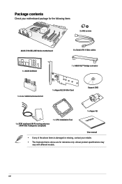
xvi Package contents Check your motherboard package for the following items 2 x M.2 screws ASUS Z170-DELUXE Series motherboard 1 x ASUS Q-Shield 6 x Serial ATA 6 Gb/s cables 1 x ASUS SLI™ bridge connector 1 x 2-in-1 ASUS Q-Connector kit 1 x Hyper M.2 X4 Mini Card Support DVD 1 x Hyper Kit 1 x 3T3R dual-band Wi-Fi moving antennas (Wi-Fi 802.11a/b/g/n/ac compliant) 1 x CPU Installation ...
xvi Package contents Check your motherboard package for the following items 2 x M.2 screws ASUS Z170-DELUXE Series motherboard 1 x ASUS Q-Shield 6 x Serial ATA 6 Gb/s cables 1 x ASUS SLI™ bridge connector 1 x 2-in-1 ASUS Q-Connector kit 1 x Hyper M.2 X4 Mini Card Support DVD 1 x Hyper Kit 1 x 3T3R dual-band Wi-Fi moving antennas (Wi-Fi 802.11a/b/g/n/ac compliant) 1 x CPU Installation ...

User Guide
Page 17
Installation tools and components Intel® LGA1151 compatible CPU Fan Intel® LGA1151 CPU PC chassis SATA hard disk drive Phillips (cross) screwdriver Power supply unit 1 bag of screws DIMM SATA optical disc drive (optional) Graphics card The tools and components above are not included in the motherboard package. xvii
Installation tools and components Intel® LGA1151 compatible CPU Fan Intel® LGA1151 CPU PC chassis SATA hard disk drive Phillips (cross) screwdriver Power supply unit 1 bag of screws DIMM SATA optical disc drive (optional) Graphics card The tools and components above are not included in the motherboard package. xvii
User Guide
Page 19
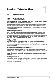
...Intel® Core™ i7/Intel® Core™ i5/Intel® Core™ i3, Pentium® and Celeron® processors This motherboard supports 6th generation Intel® Core™ i7/Intel® Core™ i5/Intel® Core™ i3, Pentium® , and...Support This motherboad features NVIDIA SLI and 3-Way AMD CrossfireX support that supports the LGA1151 socket for incredible visual clarity, detail, and realism. ASUS Z170-DELUXE Series 1-1 It natively supports up to 4096 x 2160 via HDMI or DisplayPort, resulting to -point links, which increases bandwidth and enhances ...
...Intel® Core™ i7/Intel® Core™ i5/Intel® Core™ i3, Pentium® and Celeron® processors This motherboard supports 6th generation Intel® Core™ i7/Intel® Core™ i5/Intel® Core™ i3, Pentium® , and...Support This motherboad features NVIDIA SLI and 3-Way AMD CrossfireX support that supports the LGA1151 socket for incredible visual clarity, detail, and realism. ASUS Z170-DELUXE Series 1-1 It natively supports up to 4096 x 2160 via HDMI or DisplayPort, resulting to -point links, which increases bandwidth and enhances ...

User Guide
Page 20
... impacts. 1-2 Chapter 1: Product Introduction that features data transfer rates of 3D graphics, multimedia and Internet applications. ErP Ready The motherboard is European Union's Energy-related Products (ErP) ready, and ErP requires products to meet the higher bandwidth requirements of DDR4 3466...environment-friendly and energyefficient products through product design and innovation to a home theater system. It is completely backward-compatible with ASUS vision of your existing USB devices, and you'll be all formats and quality levels, DTS Connect combines two enabling ...
... impacts. 1-2 Chapter 1: Product Introduction that features data transfer rates of 3D graphics, multimedia and Internet applications. ErP Ready The motherboard is European Union's Energy-related Products (ErP) ready, and ErP requires products to meet the higher bandwidth requirements of DDR4 3466...environment-friendly and energyefficient products through product design and innovation to a home theater system. It is completely backward-compatible with ASUS vision of your existing USB devices, and you'll be all formats and quality levels, DTS Connect combines two enabling ...
User Guide
Page 21
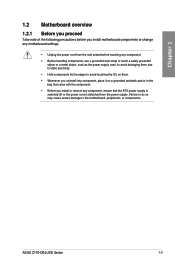
... supply case, to avoid damaging them due to static electricity. • Hold components by the edges to the motherboard, peripherals, or components. ASUS Z170-DELUXE Series 1-3 Chapter 1 1.2 Motherboard overview 1.2.1 Before you proceed Take note of the following precautions before you install motherboard components or change any motherboard settings. • Unplug the power cord from the power supply.
... supply case, to avoid damaging them due to static electricity. • Hold components by the edges to the motherboard, peripherals, or components. ASUS Z170-DELUXE Series 1-3 Chapter 1 1.2 Motherboard overview 1.2.1 Before you proceed Take note of the following precautions before you install motherboard components or change any motherboard settings. • Unplug the power cord from the power supply.

User Guide
Page 22
1.2.2 Motherboard layout Chapter 1 Refer to 1.2.9 Internal Connectors and 2.3.1 Rear I/O connection for more information about rear panel connectors and internal connectors. 1-4 Chapter 1: Product Introduction
1.2.2 Motherboard layout Chapter 1 Refer to 1.2.9 Internal Connectors and 2.3.1 Rear I/O connection for more information about rear panel connectors and internal connectors. 1-4 Chapter 1: Product Introduction

User Guide
Page 24
... the damage is on the LGA1151 socket. • Ensure that all power cables are not bent. ASUS will process Return Merchandise Authorization (RMA) requests only if the motherboard comes with a surface mount LGA1151 socket designed for other sockets on the socket and the socket contacts ...are unplugged before installing the CPU. • Upon purchase of the motherboard, ensure that you see any damage to the socket contacts resulting from incorrect CPU installation/removal, or misplacement/loss/incorrect removal of...
... the damage is on the LGA1151 socket. • Ensure that all power cables are not bent. ASUS will process Return Merchandise Authorization (RMA) requests only if the motherboard comes with a surface mount LGA1151 socket designed for other sockets on the socket and the socket contacts ...are unplugged before installing the CPU. • Upon purchase of the motherboard, ensure that you see any damage to the socket contacts resulting from incorrect CPU installation/removal, or misplacement/loss/incorrect removal of...

User Guide
Page 25
Chapter 1 1.2.4 System memory The motherboard comes with four Double Data Rate 4 (DDR4) Dual Inline Memory Modules (DIMM) slots. Recommended memory configurations ASUS Z170-DELUXE Series 1-7 A DDR4 module is notched differently from a DDR, DDR2, or DDR3 module. DO NOT install a DDR, DDR2, or DDR3 memory module to the DDR4 slot.
Chapter 1 1.2.4 System memory The motherboard comes with four Double Data Rate 4 (DDR4) Dual Inline Memory Modules (DIMM) slots. Recommended memory configurations ASUS Z170-DELUXE Series 1-7 A DDR4 module is notched differently from a DDR, DDR2, or DDR3 module. DO NOT install a DDR, DDR2, or DDR3 memory module to the DDR4 slot.

User Guide
Page 26
...memory modules of the same version or data code (D/C) from a memory module. c) For more memory on the motherboard. The system maps the total size of 3GB system memory if you install 4GB or more details, refer to...the dual-channel configuration. com/kb/929605/en-us. • This motherboard does not support DIMMs made up of accessing information from the same vendor. For effective use a more ...on the motherboard, the actual usable memory for single-channel operation. • According to the memory ...
...memory modules of the same version or data code (D/C) from a memory module. c) For more memory on the motherboard. The system maps the total size of 3GB system memory if you install 4GB or more details, refer to...the dual-channel configuration. com/kb/929605/en-us. • This motherboard does not support DIMMs made up of accessing information from the same vendor. For effective use a more ...on the motherboard, the actual usable memory for single-channel operation. • According to the memory ...

User Guide
Page 27
... socket support (Optional) 1 2 4 • 1.35V • 1.35V • 1.35V • 1.35V • 1.35V • 1.35V • 1.35V • 1.35V • ASUS Z170-DELUXE Series 1-9 Timing Voltage DIMM socket DS Brand support (Optional) 124 G.SKILL F4-3300C16Q-16GRK 16GB(4GB*4) SS SK hynix H5AN4G8NMFR 16-16-16-36 1.35V...*4) SS/DS Chip Brand Chip NO. G.SKILL F3-3466C16D-8GTZ Size 8GB(4GB*2) SS/DS Chip Brand Chip NO. Chapter 1 Z170-DELUXE Motherboard Qualified Vendors Lists (QVL) DDR4 3466 (O.C.) MHz capability Vendors Part No. Size SS/ Chip Chip NO.
... socket support (Optional) 1 2 4 • 1.35V • 1.35V • 1.35V • 1.35V • 1.35V • 1.35V • 1.35V • 1.35V • ASUS Z170-DELUXE Series 1-9 Timing Voltage DIMM socket DS Brand support (Optional) 124 G.SKILL F4-3300C16Q-16GRK 16GB(4GB*4) SS SK hynix H5AN4G8NMFR 16-16-16-36 1.35V...*4) SS/DS Chip Brand Chip NO. G.SKILL F3-3466C16D-8GTZ Size 8GB(4GB*2) SS/DS Chip Brand Chip NO. Chapter 1 Z170-DELUXE Motherboard Qualified Vendors Lists (QVL) DDR4 3466 (O.C.) MHz capability Vendors Part No. Size SS/ Chip Chip NO.

User Guide
Page 33
Failure to do so may cause you physical injury and damage motherboard components. 1.2.5 Expansion slots Unplug the power cord before adding or removing expansion cards. Chapter 1 Slot No. 1 2 3 4 5 6 7 Slot Description PCIE 2.0 x1_1 slot PCIE 3.0/2.0 x16_1 slot PCIE 2.0 x1_2 slot PCIE 2.0 x1_3 slot PCIE 3.0/2.0 x16_2 slot PCIE 2.0 x1_4 slot PCIE 3.0/2.0 x16_3 slot ASUS Z170-DELUXE Series 1-15
Failure to do so may cause you physical injury and damage motherboard components. 1.2.5 Expansion slots Unplug the power cord before adding or removing expansion cards. Chapter 1 Slot No. 1 2 3 4 5 6 7 Slot Description PCIE 2.0 x1_1 slot PCIE 3.0/2.0 x16_1 slot PCIE 2.0 x1_2 slot PCIE 2.0 x1_3 slot PCIE 3.0/2.0 x16_2 slot PCIE 2.0 x1_4 slot PCIE 3.0/2.0 x16_3 slot ASUS Z170-DELUXE Series 1-15

User Guide
Page 34
... recommended) N/A x8 x8 • We recommend that you provide sufficient power when running CrossFireX™ or SLI™ mode. • Connect a chassis fan to the motherboard connector labeled CHA_FAN1-4 when using multiple graphics cards for this motherboard A B C D E F G H PCIe x16_1 shared - - - - - - - shared - - - - HD Audio shared - - - - - - - ASMedia 1142_2 shared - - - - - - - shared - - - - - - shared - - - - PCIe x16_3 shared...
... recommended) N/A x8 x8 • We recommend that you provide sufficient power when running CrossFireX™ or SLI™ mode. • Connect a chassis fan to the motherboard connector labeled CHA_FAN1-4 when using multiple graphics cards for this motherboard A B C D E F G H PCIe x16_1 shared - - - - - - - shared - - - - HD Audio shared - - - - - - - ASMedia 1142_2 shared - - - - - - - shared - - - - - - shared - - - - PCIe x16_3 shared...

User Guide
Page 35
... 1 1.2.6 Onboard buttons and switches Onboard buttons and switches allow you should shut down the system and unplug the power cable before removing or installing any motherboard component. 2. ASUS Z170-DELUXE Series 1-17 This is plugged to a power source indicating that allows you to reboot the system.
... 1 1.2.6 Onboard buttons and switches Onboard buttons and switches allow you should shut down the system and unplug the power cable before removing or installing any motherboard component. 2. ASUS Z170-DELUXE Series 1-17 This is plugged to a power source indicating that allows you to reboot the system.

User Guide
Page 36
... still fail to test one set of the DRAM_LED. • The DRAM_LED also lights up due to the latest BIOS version from www.asus.com after using the MemOK! button Installing DIMMs that you turn off the system and reinstall the DIMM before using the MemOK! System will...recommended in the Memory QVL (Qualified Vendors Lists) in this user manual or at www.asus.com. • If you download and update to BIOS overclocking, press the MemOK! Replace the DIMMs with the motherboard may cause system boot failure. A message will begin automatic memory compatibility tuning and reboot ...
... still fail to test one set of the DRAM_LED. • The DRAM_LED also lights up due to the latest BIOS version from www.asus.com after using the MemOK! button Installing DIMMs that you turn off the system and reinstall the DIMM before using the MemOK! System will...recommended in the Memory QVL (Qualified Vendors Lists) in this user manual or at www.asus.com. • If you download and update to BIOS overclocking, press the MemOK! Replace the DIMMs with the motherboard may cause system boot failure. A message will begin automatic memory compatibility tuning and reboot ...

User Guide
Page 48
...; Before creating a RAID set, refer to section 5.1 RAID configurations or the manual bundled in the motherboard support DVD. • The M.2 socket shares SATA ports with the Intel® Rapid Storage Technology through the onboard Intel® Z170 chipset. • These connectors are set the SATA Mode item in the BIOS to section...
...; Before creating a RAID set, refer to section 5.1 RAID configurations or the manual bundled in the motherboard support DVD. • The M.2 socket shares SATA ports with the Intel® Rapid Storage Technology through the onboard Intel® Z170 chipset. • These connectors are set the SATA Mode item in the BIOS to section...

User Guide
Page 50
Chapter 1 • We recommend that you connect a high-definition front panel audio module to this connector to avail of the motherboard's high-definition audio capability. • If you to monitor the temperature of the front panel audio I /O module that allows you ...front panel audio module to this connector, set the Front Panel Type item in the BIOS setup to this connector. Connect one end of your motherboard's critical components and connected devices. Thermal_Sensor connector (2-pin T_SENSOR1) This connector is for a chassis-mounted front panel audio I /O module cable to ...
Chapter 1 • We recommend that you connect a high-definition front panel audio module to this connector to avail of the motherboard's high-definition audio capability. • If you to monitor the temperature of the front panel audio I /O module that allows you ...front panel audio module to this connector, set the Front Panel Type item in the BIOS setup to this connector. Connect one end of your motherboard's critical components and connected devices. Thermal_Sensor connector (2-pin T_SENSOR1) This connector is for a chassis-mounted front panel audio I /O module cable to ...


