E787 MANUAL TERMINATOR English
Page 5
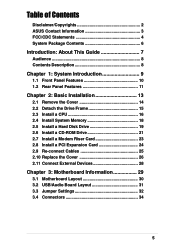
Table of Contents Disclaimer/Copyrights 2 ASUS Contact Information 3 FCC/CDC Statements 4 System Package Contents 6 Introduction: About This Guide 7 Audience 8 Contents Description 8 Chapter 1: System Introduction 9 1.1 Front Panel Features 10 1.2 Rear Panel Features ... 2.7 Install a Modem Riser Card 23 2.8 Install a PCI Expansion Card 24 2.9 Re-connect Cables 25 2.10 Replace the Cover 26 2.11 Connect External Devices 28 Chapter 3: Motherboard Information 29 3.1 Motherboard Layout 30 3.2 USB/Audio Board Layout 31 3.3 Jumper Settings 32 3.4 Connectors 34 5
Table of Contents Disclaimer/Copyrights 2 ASUS Contact Information 3 FCC/CDC Statements 4 System Package Contents 6 Introduction: About This Guide 7 Audience 8 Contents Description 8 Chapter 1: System Introduction 9 1.1 Front Panel Features 10 1.2 Rear Panel Features ... 2.7 Install a Modem Riser Card 23 2.8 Install a PCI Expansion Card 24 2.9 Re-connect Cables 25 2.10 Replace the Cover 26 2.11 Connect External Devices 28 Chapter 3: Motherboard Information 29 3.1 Motherboard Layout 30 3.2 USB/Audio Board Layout 31 3.3 Jumper Settings 32 3.4 Connectors 34 5

E787 MANUAL TERMINATOR English
Page 6
System Package Contents The following checklist enumerates the components included in the standard system package. 1) System Chassis 2) Motherboard 3) Switching Power Supply 4) 1.44MB Floppy Disk Drive 5) CD-ROM Drive (optional) 6) 56K PCI Modem Card (optional) 7) Support CD with Drivers and Utilities 8) Installation Guide NOTE If you need them. 6 It saves you a lot of time not having to hunt down components when you are assembling the system by yourself, make sure to prepare all the components before starting.
System Package Contents The following checklist enumerates the components included in the standard system package. 1) System Chassis 2) Motherboard 3) Switching Power Supply 4) 1.44MB Floppy Disk Drive 5) CD-ROM Drive (optional) 6) 56K PCI Modem Card (optional) 7) Support CD with Drivers and Utilities 8) Installation Guide NOTE If you need them. 6 It saves you a lot of time not having to hunt down components when you are assembling the system by yourself, make sure to prepare all the components before starting.

E787 MANUAL TERMINATOR English
Page 8
...to install components into the barebone system through illustrated step-by-step instructions. 4. Chapter 3: Motherboard Information This chapter gives information about the CUSC motherboard that include target audience and chapter description. 2. It also includes information on the USB/audio...About This Guide Checklist Audience This installation guide is intended for experienced users and integrators with the ASUS Terminator Barebone System.This chapter includes the motherboard layout, jumper settings, and connector locations. Introduction: About This Guide This part contains an ...
...to install components into the barebone system through illustrated step-by-step instructions. 4. Chapter 3: Motherboard Information This chapter gives information about the CUSC motherboard that include target audience and chapter description. 2. It also includes information on the USB/audio...About This Guide Checklist Audience This installation guide is intended for experienced users and integrators with the ASUS Terminator Barebone System.This chapter includes the motherboard layout, jumper settings, and connector locations. Introduction: About This Guide This part contains an ...

E787 MANUAL TERMINATOR English
Page 10
... composed of the ASUS CUSC motherboard, a power supply, and a floppy disk drive in some models. The following figures show the connectors as in the above figure. 10 Chapter 1: System Introduction Push the dotted area of the door to open it and show the front panel features. 1.1 Front Panel Features The ASUS Terminator barebone system...
... composed of the ASUS CUSC motherboard, a power supply, and a floppy disk drive in some models. The following figures show the connectors as in the above figure. 10 Chapter 1: System Introduction Push the dotted area of the door to open it and show the front panel features. 1.1 Front Panel Features The ASUS Terminator barebone system...

E787 MANUAL TERMINATOR English
Page 12
You will see here the standard components that come already installed in the system and the places where you remove the cover and flip out the drive frame. 1.3 Internal Features The figure below shows the internal view of the system when you can install the other required components to get the system running. Two 5.25" 3.5" HDD 3.5" Floppy Drive Bays Drive Bay Drive Power Supply Modem Card Motherboard USB/audio Board 12 Chapter 1: System Introduction
You will see here the standard components that come already installed in the system and the places where you remove the cover and flip out the drive frame. 1.3 Internal Features The figure below shows the internal view of the system when you can install the other required components to get the system running. Two 5.25" 3.5" HDD 3.5" Floppy Drive Bays Drive Bay Drive Power Supply Modem Card Motherboard USB/audio Board 12 Chapter 1: System Introduction
E787 MANUAL TERMINATOR English
Page 16
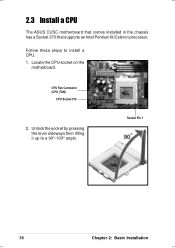
2.3 Install a CPU The ASUS CUSC motherboard that comes installed in the chassis has a Socket 370 that supports an Intel Pentium III/Celeron processor. CPU Fan Connector (CPU_FAN) CPU Socket 370 2. Locate the CPU socket on the motherboard. Unlock the socket by pressing the lever sideways then lifting it up to install a CPU. 1. Socket Pin 1 16 Chapter 2: Basic Installation Follow these steps to a 90°-100° angle.
2.3 Install a CPU The ASUS CUSC motherboard that comes installed in the chassis has a Socket 370 that supports an Intel Pentium III/Celeron processor. CPU Fan Connector (CPU_FAN) CPU Socket 370 2. Locate the CPU socket on the motherboard. Unlock the socket by pressing the lever sideways then lifting it up to install a CPU. 1. Socket Pin 1 16 Chapter 2: Basic Installation Follow these steps to a 90°-100° angle.

E787 MANUAL TERMINATOR English
Page 17
...Carefully insert the CPU into the socket to prevent bending the pins and damaging the CPU. Connect the CPU fan cable to secure the CPU. ASUS Terminator Barebone System 17 Position the CPU above the socket such that its orientation or check for bent pins. Notched Corner 4. The lever clicks in one...sure that the socket is parallel to the picture in place. Socket Pin 1 5. Push down the lever to the 3-pin CPU_FAN connector on the motherboard. Refer to the socket. DO NOT force the CPU into the socket until it fits in step 1. The CPU fits only in place indicating ...
...Carefully insert the CPU into the socket to prevent bending the pins and damaging the CPU. Connect the CPU fan cable to secure the CPU. ASUS Terminator Barebone System 17 Position the CPU above the socket such that its orientation or check for bent pins. Notched Corner 4. The lever clicks in one...sure that the socket is parallel to the picture in place. Socket Pin 1 5. Push down the lever to the 3-pin CPU_FAN connector on the motherboard. Refer to the socket. DO NOT force the CPU into the socket until it fits in step 1. The CPU fits only in place indicating ...

E787 MANUAL TERMINATOR English
Page 18
... 2: Basic Installation Locate the DIMM sockets on the socket such that they fit in place and the DIMM is properly seated. Align a DIMM on the motherboard. 2.4 Install System Memory The motherboard includes two 168-pin Dual Inline Memory Module (DIMM) sockets. DIMM Notch Socket Break CAUTION!
... 2: Basic Installation Locate the DIMM sockets on the socket such that they fit in place and the DIMM is properly seated. Align a DIMM on the motherboard. 2.4 Install System Memory The motherboard includes two 168-pin Dual Inline Memory Module (DIMM) sockets. DIMM Notch Socket Break CAUTION!

E787 MANUAL TERMINATOR English
Page 20
Use the cable with Pin 1 on the motherboard. Connect the other end of the IDE ribbon cable to the IDE interface at the back of the HDD. Primary IDE Connector (IDE1) 20 Chapter 2: ...
Use the cable with Pin 1 on the motherboard. Connect the other end of the IDE ribbon cable to the IDE interface at the back of the HDD. Primary IDE Connector (IDE1) 20 Chapter 2: ...

E787 MANUAL TERMINATOR English
Page 22
.... 6. Connect the other end of the audio cable to the power connector at the back of the CD-ROM, matching the red stripe on the motherboard. 9. Connect one end of the CDROM audio cable to the IDE interface at the back of the CD-ROM. IDE Ribbon Cable 7. Connect one... connector at the back of the IDE ribbon cable to Pin 1 Power Cable (P6) 8. Use the cable with Pin 1 CD-ROM Audio Cable on the motherboard. CD-ROM Connector (CD) Secondary IDE Connector (IDE2) 22 Chapter 2: Basic Installation Connect the other end of the CD-ROM. 2.6 Install a CD-ROM Drive 5. ...
.... 6. Connect the other end of the audio cable to the power connector at the back of the CD-ROM, matching the red stripe on the motherboard. 9. Connect one end of the CDROM audio cable to the IDE interface at the back of the CD-ROM. IDE Ribbon Cable 7. Connect one... connector at the back of the IDE ribbon cable to Pin 1 Power Cable (P6) 8. Use the cable with Pin 1 CD-ROM Audio Cable on the motherboard. CD-ROM Connector (CD) Secondary IDE Connector (IDE2) 22 Chapter 2: Basic Installation Connect the other end of the CD-ROM. 2.6 Install a CD-ROM Drive 5. ...

E787 MANUAL TERMINATOR English
Page 23
... riser card. 1. Refer to the AMR slot and its side. 2. Align the modem card golden fingers to the instructions in the Terminator barebone system. Remove the metal bracket cover opposite the AMR expansion slot. 3. Press the card firmly until the it is an optional...that supports a modem riser card. The figure on the AMR Slot ASUS Terminator Barebone System 23 Connect to a Telephone Line Connect to the slot opening on the AMR slot. Bracket Screw 5. 2.7 Install a Modem Riser Card The motherboard includes an AMR slot that you acquired a model without a modem ...
... riser card. 1. Refer to the AMR slot and its side. 2. Align the modem card golden fingers to the instructions in the Terminator barebone system. Remove the metal bracket cover opposite the AMR expansion slot. 3. Press the card firmly until the it is an optional...that supports a modem riser card. The figure on the AMR Slot ASUS Terminator Barebone System 23 Connect to a Telephone Line Connect to the slot opening on the AMR slot. Bracket Screw 5. 2.7 Install a Modem Riser Card The motherboard includes an AMR slot that you acquired a model without a modem ...

E787 MANUAL TERMINATOR English
Page 24
... the PCI card golden fingers to the slot opening on its metal bracket to the PCI slot and its side. 2. 2.8 Install a PCI Expansion Card The motherboard has two 32-bit PCI slots (one shared with a bracket screw. The figure on the right shows a sample PCI network card that you can install...
... the PCI card golden fingers to the slot opening on its metal bracket to the PCI slot and its side. 2. 2.8 Install a PCI Expansion Card The motherboard has two 32-bit PCI slots (one shared with a bracket screw. The figure on the right shows a sample PCI network card that you can install...

E787 MANUAL TERMINATOR English
Page 25
... You may have disconnected some cables when you replace the chassis cover. Connect the Line Out/Mic cable to their corresponding connectors on the motherboard, matching the red pin stripe with Pin 1. 4. USB1 Connector Speaker Connector Speaker Ground Ground +5V PLED Power LED +5 V Ground Reset...1 FLOUT Lead (for Line Out Cable) MIC2 Lead (for Microphone Cable) ASUS Terminator Barebone System 25 The figures below show the front panel cables and their respective leads in the PANEL connector on the motherboard, matching the red pin stripe with Pin 1. Connect the power switch and ...
... You may have disconnected some cables when you replace the chassis cover. Connect the Line Out/Mic cable to their corresponding connectors on the motherboard, matching the red pin stripe with Pin 1. 4. USB1 Connector Speaker Connector Speaker Ground Ground +5V PLED Power LED +5 V Ground Reset...1 FLOUT Lead (for Line Out Cable) MIC2 Lead (for Microphone Cable) ASUS Terminator Barebone System 25 The figures below show the front panel cables and their respective leads in the PANEL connector on the motherboard, matching the red pin stripe with Pin 1. Connect the power switch and ...

E787 MANUAL TERMINATOR English
Page 29
M/B Information ASUS Terminator Barebone System 29 It also includes information on the USB/ audio board located on the front panel. Chapter 3 This chapter gives information about the CUSC motherboard that comes with the ASUS Terminator Barebone System.This chapter includes the motherboard layout, jumper settings, and connector locations. In cases when changing motherboard settings require corresponding BIOS settings adjustments, enter BIOS Setup by pressing the Delete key during boot up (Power-On Self Test).
M/B Information ASUS Terminator Barebone System 29 It also includes information on the USB/ audio board located on the front panel. Chapter 3 This chapter gives information about the CUSC motherboard that comes with the ASUS Terminator Barebone System.This chapter includes the motherboard layout, jumper settings, and connector locations. In cases when changing motherboard settings require corresponding BIOS settings adjustments, enter BIOS Setup by pressing the Delete key during boot up (Power-On Self Test).

E787 MANUAL TERMINATOR English
Page 30
... Socket 2 (64/72-bit, 168-pin module) ® Line Out Socket 370 Line In Mic In CPU_FAN RJ-45 CH_FAN LANLED ASUS Mozart USB T: Port0 B: Port1 USBPWR1 CD FLOUT AUX MIC2 PCI Slot 1 Audio Codec PDN WOR PCI Slot 2 MODEM Audio Modem Riser... Secondary IDE CR2032 3V Lithium Cell CMOS Power 1 1 USB1 USBPWR CLRTC IR PANEL IDELED 30 Chapter 3: Motherboard Information 3.1 Motherboard Layout Refer to the layout below to locate specific motherboard components. The motherboard has a side connector for a detachable extension module (CGAEX) that includes a serial port (COM1) and ...
... Socket 2 (64/72-bit, 168-pin module) ® Line Out Socket 370 Line In Mic In CPU_FAN RJ-45 CH_FAN LANLED ASUS Mozart USB T: Port0 B: Port1 USBPWR1 CD FLOUT AUX MIC2 PCI Slot 1 Audio Codec PDN WOR PCI Slot 2 MODEM Audio Modem Riser... Secondary IDE CR2032 3V Lithium Cell CMOS Power 1 1 USB1 USBPWR CLRTC IR PANEL IDELED 30 Chapter 3: Motherboard Information 3.1 Motherboard Layout Refer to the layout below to locate specific motherboard components. The motherboard has a side connector for a detachable extension module (CGAEX) that includes a serial port (COM1) and ...

E787 MANUAL TERMINATOR English
Page 31
3.2 USB/Audio Board Layout The USB/audio board is located on the front panel to MIC2 Lead on the Motherboard Connect to support externally accessible connectors including two USB, headphone, and microphone connectors. Front Panel Connectors USB T: Port0 B: Port1 USB2P UAEX ® LOUT LO2 MIC MIC2 Connect to USB1 Connector on the Motherboard Connect to FLOUT Lead on the Motherboard ASUS Terminator Barebone System 31
3.2 USB/Audio Board Layout The USB/audio board is located on the front panel to MIC2 Lead on the Motherboard Connect to support externally accessible connectors including two USB, headphone, and microphone connectors. Front Panel Connectors USB T: Port0 B: Port1 USB2P UAEX ® LOUT LO2 MIC MIC2 Connect to USB1 Connector on the Motherboard Connect to FLOUT Lead on the Motherboard ASUS Terminator Barebone System 31

E787 MANUAL TERMINATOR English
Page 32
... supply in low power mode) using the connected USB devices. CUSC ® CUSC USB Device Wake Up USBPWR USBPWR1 12 +5VSB 23 +5V 32 Chapter 3: Motherboard Information
... supply in low power mode) using the connected USB devices. CUSC ® CUSC USB Device Wake Up USBPWR USBPWR1 12 +5VSB 23 +5V 32 Chapter 3: Motherboard Information

E787 MANUAL TERMINATOR English
Page 34
... GND IRTX Standard Infrared (SIR) Front View Back View SIR CIR IRTX +5V GND (NC) IRRX USB Power USBP2- CUSC System Panel Connectors 34 Chapter 3: Motherboard Information
... GND IRTX Standard Infrared (SIR) Front View Back View SIR CIR IRTX +5V GND (NC) IRRX USB Power USBP2- CUSC System Panel Connectors 34 Chapter 3: Motherboard Information


