
TUF X299 MARK 1 Users ManualEnglish
Page 1
Motherboard TUF X299 MARK 1
Motherboard TUF X299 MARK 1

TUF X299 MARK 1 Users ManualEnglish
Page 3
... About this guide...vii TUF X299 MARK 1 specifications summary ix Package contents...xiv Installation tools and components xv Chapter 1: Product Introduction 1.1 Motherboard overview 1-1 1.1.1 Before you proceed 1-1 1.1.2 Motherboard layout 1-2 1.1.3 Central Processing...Jumpers 1-11 1.1.8 Onboard LEDs 1-13 1.1.9 Internal connectors 1-14 Chapter 2: Basic Installation 2.1 Building your PC system 2-1 2.1.1 Motherboard installation 2-1 2.1.2 CPU installation 2-3 2.1.3 CPU heatsink and fan assembly installation 2-5 2.1.4 DIMM installation 2-6 2.1.5 ATX power connection ...
... About this guide...vii TUF X299 MARK 1 specifications summary ix Package contents...xiv Installation tools and components xv Chapter 1: Product Introduction 1.1 Motherboard overview 1-1 1.1.1 Before you proceed 1-1 1.1.2 Motherboard layout 1-2 1.1.3 Central Processing...Jumpers 1-11 1.1.8 Onboard LEDs 1-13 1.1.9 Internal connectors 1-14 Chapter 2: Basic Installation 2.1 Building your PC system 2-1 2.1.1 Motherboard installation 2-1 2.1.2 CPU installation 2-3 2.1.3 CPU heatsink and fan assembly installation 2-5 2.1.4 DIMM installation 2-6 2.1.5 ATX power connection ...

TUF X299 MARK 1 Users ManualEnglish
Page 6
...cables are connected. These devices could interrupt the grounding circuit. • Ensure that your power supply is broken, do not try to or from the motherboard, ensure that came with the product, contact a qualified service technician or your area. Operation safety • Before installing the... motherboard and adding devices on it may become wet. • Place the product on a stable surface. • If you add a device. • Before connecting or ...
...cables are connected. These devices could interrupt the grounding circuit. • Ensure that your power supply is broken, do not try to or from the motherboard, ensure that came with the product, contact a qualified service technician or your area. Operation safety • Before installing the... motherboard and adding devices on it may become wet. • Place the product on a stable surface. • If you add a device. • Before connecting or ...

TUF X299 MARK 1 Users ManualEnglish
Page 7
... and software updates. 1. Chapter 3: BIOS Setup This chapter tells how to the following parts: 1. ASUS website The ASUS website (www.asus.com) provides updated information on the motherboard. 2. Chapter 4: RAID Support This chapter describes the RAID configurations. Where to find more information Refer... 1: Product Introduction This chapter describes the features of the switches, jumpers, and connectors on ASUS hardware and software products. 2. It includes description of the motherboard and the new technology it supports. How this guide This user guide contains the information you...
... and software updates. 1. Chapter 3: BIOS Setup This chapter tells how to the following parts: 1. ASUS website The ASUS website (www.asus.com) provides updated information on the motherboard. 2. Chapter 4: RAID Support This chapter describes the RAID configurations. Where to find more information Refer... 1: Product Introduction This chapter describes the features of the switches, jumpers, and connectors on ASUS hardware and software products. 2. It includes description of the motherboard and the new technology it supports. How this guide This user guide contains the information you...

TUF X299 MARK 1 Users ManualEnglish
Page 14
Package contents Check your motherboard package for the following items. Motherboard Cables Accessories Application DVD Documentation ASUS TUF X299 MARK 1 motherboard 4 x Serial ATA 6.0 Gb/s cables 1 x SLI HB BRIDGE(2-WAY-M) 1 x SLI BRIDGE(3-WAY) 1 x Q-Connector 1 x M.2 vertical bracket 1 x M.2 screw package 1 x ASUS Q-Shield 1 x TUF VGA holder 1 x TUF Dongle 1 x TUF INSIDE sticker 1 x STAY COOL BE TUF sticker 1 x TUF accessory package - 3 x PCIe x16 slot dust covers - 1 x PCIe x4 slot dust...
Package contents Check your motherboard package for the following items. Motherboard Cables Accessories Application DVD Documentation ASUS TUF X299 MARK 1 motherboard 4 x Serial ATA 6.0 Gb/s cables 1 x SLI HB BRIDGE(2-WAY-M) 1 x SLI BRIDGE(3-WAY) 1 x Q-Connector 1 x M.2 vertical bracket 1 x M.2 screw package 1 x ASUS Q-Shield 1 x TUF VGA holder 1 x TUF Dongle 1 x TUF INSIDE sticker 1 x STAY COOL BE TUF sticker 1 x TUF accessory package - 3 x PCIe x16 slot dust covers - 1 x PCIe x4 slot dust...

TUF X299 MARK 1 Users ManualEnglish
Page 15
xv Installation tools and components Intel® LGA 2066 compatible CPU Fan Intel® LGA 2066 CPU PC chassis SATA hard disk drive Phillips (cross) screwdriver Power supply unit 1 bag of screws DIMM SATA optical disc drive (optional) Graphics card M.2 SSD module (optional) The tools and components in the table above are not included in the motherboard package.
xv Installation tools and components Intel® LGA 2066 compatible CPU Fan Intel® LGA 2066 CPU PC chassis SATA hard disk drive Phillips (cross) screwdriver Power supply unit 1 bag of screws DIMM SATA optical disc drive (optional) Graphics card M.2 SSD module (optional) The tools and components in the table above are not included in the motherboard package.
TUF X299 MARK 1 Users ManualEnglish
Page 17
...place it on a grounded antistatic pad or in the bag that came with the component. • Before you install motherboard components or change any component. • Before handling components, use a grounded wrist strap or touch a safely grounded ...Motherboard overview 1.1.1 Before you proceed Take note of the following precautions before you install or remove any component, ensure that the ATX power supply is switched off or the power cord is detached from the wall socket before touching any motherboard settings. • Unplug the power cord from the power supply. ASUS TUF X299 MARK...
...place it on a grounded antistatic pad or in the bag that came with the component. • Before you install motherboard components or change any component. • Before handling components, use a grounded wrist strap or touch a safely grounded ...Motherboard overview 1.1.1 Before you proceed Take note of the following precautions before you install or remove any component, ensure that the ATX power supply is switched off or the power cord is detached from the wall socket before touching any motherboard settings. • Unplug the power cord from the power supply. ASUS TUF X299 MARK...

TUF X299 MARK 1 Users ManualEnglish
Page 18
1.1.2 Motherboard layout Chapter 1 Refer to 1.1.9 Internal connectors and 2.3.1 Rear I/O connection for more information about rear panel connectors and internal connectors. 1-2 Chapter 1: Product Introduction
1.1.2 Motherboard layout Chapter 1 Refer to 1.1.9 Internal connectors and 2.3.1 Rear I/O connection for more information about rear panel connectors and internal connectors. 1-2 Chapter 1: Product Introduction

TUF X299 MARK 1 Users ManualEnglish
Page 20
... CPU. • Upon purchase of the motherboard, ensure that all power cables are not bent. Chapter 1 • Ensure that the PnP cap is shipment/ transit-related. • Keep the cap after installing the motherboard. ASUS will process Return Merchandise Authorization (RMA) requests... only if the motherboard comes with a surface mount LGA2066 socket designed for the Intel® Core™ X-series Processors...
... CPU. • Upon purchase of the motherboard, ensure that all power cables are not bent. Chapter 1 • Ensure that the PnP cap is shipment/ transit-related. • Keep the cap after installing the motherboard. ASUS will process Return Merchandise Authorization (RMA) requests... only if the motherboard comes with a surface mount LGA2066 socket designed for the Intel® Core™ X-series Processors...

TUF X299 MARK 1 Users ManualEnglish
Page 21
Recommended memory configurations Intel® Core™ X-series Processors (6-core or above) ASUS TUF X299 MARK 1 1-5 DO NOT install a DDR, DDR2, or DDR3 memory module to the DDR4 slot. A DDR4 module is notched differently from a DDR, DDR2, or DDR3 module. Chapter 1 1.1.4 System memory The motherboard comes with eight DDR4 (Double Data Rate 4) Dual Inline Memory Modules (DIMM) slots.
Recommended memory configurations Intel® Core™ X-series Processors (6-core or above) ASUS TUF X299 MARK 1 1-5 DO NOT install a DDR, DDR2, or DDR3 memory module to the DDR4 slot. A DDR4 module is notched differently from a DDR, DDR2, or DDR3 module. Chapter 1 1.1.4 System memory The motherboard comes with eight DDR4 (Double Data Rate 4) Dual Inline Memory Modules (DIMM) slots.

TUF X299 MARK 1 Users ManualEnglish
Page 23
Chapter 1 Slot No. 1 2 3 4 5 Slot Description PCIE 3.0/2.0 x16_1 slot PCIE 3.0/2.0 x4_1 slot PCIE 3.0/2.0 x16_2 slot PCIE 3.0/2.0 x4_2 slot PCIE 3.0/2.0 x16_3 slot ASUS TUF X299 MARK 1 1-7 Failure to do so may cause you physical injury and damage motherboard components. 1.1.5 Expansion slots Unplug the power cord before adding or removing expansion cards.
Chapter 1 Slot No. 1 2 3 4 5 Slot Description PCIE 3.0/2.0 x16_1 slot PCIE 3.0/2.0 x4_1 slot PCIE 3.0/2.0 x16_2 slot PCIE 3.0/2.0 x4_2 slot PCIE 3.0/2.0 x16_3 slot ASUS TUF X299 MARK 1 1-7 Failure to do so may cause you physical injury and damage motherboard components. 1.1.5 Expansion slots Unplug the power cord before adding or removing expansion cards.

TUF X299 MARK 1 Users ManualEnglish
Page 25
... seconds for successful boot. • Refer to boot after the whole tuning process, the DRAM_LED lights continuously. Replace the DIMMs with the motherboard may cause system boot failure. It takes about 5-10 seconds. • If your system fails to boot up when the DIMM is ...the computer. System will appear during the tuning process, the system continues memory tuning after turning on a bare or open-case system. ASUS TUF X299 MARK 1 1-9 If the installed DIMMs still fail to section 1.1.8 Onboard LEDs for overclockers and gamers who continually change settings to boot and load...
... seconds for successful boot. • Refer to boot after the whole tuning process, the DRAM_LED lights continuously. Replace the DIMMs with the motherboard may cause system boot failure. It takes about 5-10 seconds. • If your system fails to boot up when the DIMM is ...the computer. System will appear during the tuning process, the system continues memory tuning after turning on a bare or open-case system. ASUS TUF X299 MARK 1 1-9 If the installed DIMMs still fail to section 1.1.8 Onboard LEDs for overclockers and gamers who continually change settings to boot and load...

TUF X299 MARK 1 Users ManualEnglish
Page 26
2. The Standby Power LED (SB_PWR) also lights up when the system is plugged to power up or wake up the system. Chapter 1 1-10 Chapter 1: Product Introduction Power-on button The motherboard comes with a power-on button that allows you to a power source indicating that you should shut down the system and unplug the power cable before removing or installing any motherboard component.
2. The Standby Power LED (SB_PWR) also lights up when the system is plugged to power up or wake up the system. Chapter 1 1-10 Chapter 1: Product Introduction Power-on button The motherboard comes with a power-on button that allows you to a power source indicating that you should shut down the system and unplug the power cable before removing or installing any motherboard component.

TUF X299 MARK 1 Users ManualEnglish
Page 29
... with a standby power LED. This is ON, in sleep mode, or in any motherboard component. The LED lights up until the problem is solved. 2. The illustration below shows the location of these key components during POST (Power-On Self-... the power cable before removing or plugging in soft-off mode. POST State LEDs The POST State LEDs provide the status of the onboard LED. ASUS TUF X299 MARK 1 1-13 Chapter 1 1.1.8 Onboard LEDs 1.
... with a standby power LED. This is ON, in sleep mode, or in any motherboard component. The LED lights up until the problem is solved. 2. The illustration below shows the location of these key components during POST (Power-On Self-... the power cable before removing or plugging in soft-off mode. POST State LEDs The POST State LEDs provide the status of the onboard LED. ASUS TUF X299 MARK 1 1-13 Chapter 1 1.1.8 Onboard LEDs 1.

TUF X299 MARK 1 Users ManualEnglish
Page 31
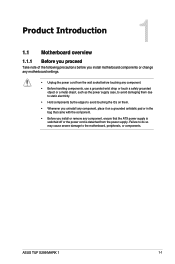
ASUS TUF X299 MARK 1 1-15 We recommend that supports HD Audio. The latest USB 3.1 Gen 2 connectivity provides data transfer speeds of up to avail of the front panel audio I/O .... USB 3.1 Gen 2 front panel connector (U31G2_E3) This connector allows you connect a high-definition front panel audio module to this connector. Connect one end of the motherboard's high-definition audio capability. 3. Chapter 1 2. Front panel audio connector (10-1 pin AAFP) This connector is for additional USB 3.1 Gen 2 ports.
ASUS TUF X299 MARK 1 1-15 We recommend that supports HD Audio. The latest USB 3.1 Gen 2 connectivity provides data transfer speeds of up to avail of the front panel audio I/O .... USB 3.1 Gen 2 front panel connector (U31G2_E3) This connector allows you connect a high-definition front panel audio module to this connector. Connect one end of the motherboard's high-definition audio capability. 3. Chapter 1 2. Front panel audio connector (10-1 pin AAFP) This connector is for additional USB 3.1 Gen 2 ports.
TUF X299 MARK 1 Users ManualEnglish
Page 33
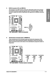
Thermal sensor connector (2-pin T_SENSOR1-3) These connectors are for USB 2.0 ports. Connect the thermistor cable and place the sensor on the device or the motherboard's component to 480 Mb/s connection speed. 6. This USB connector complies with USB 2.0 specification that monitors the temperature of the system chassis. USB 2.0 connector (10-1 pin ... USB module cable to this connector, then install the module to a slot opening at the back of the devices and the critical components inside the motherboard. ASUS TUF X299 MARK 1 1-17
Thermal sensor connector (2-pin T_SENSOR1-3) These connectors are for USB 2.0 ports. Connect the thermistor cable and place the sensor on the device or the motherboard's component to 480 Mb/s connection speed. 6. This USB connector complies with USB 2.0 specification that monitors the temperature of the system chassis. USB 2.0 connector (10-1 pin ... USB module cable to this connector, then install the module to a slot opening at the back of the devices and the critical components inside the motherboard. ASUS TUF X299 MARK 1 1-17

TUF X299 MARK 1 Users ManualEnglish
Page 34
...to disable Q-Fan functions if you connect powerful fans (1A or above ) onto the H_AMP_FAN connector. • W_PUMP+ function support depends on the motherboard, ensuring that the black wire of each cable matches the ground pin of the connector. Insufficient air flow inside the system may damage the...• The CPU_FAN connector supports the CPU fan of maximum 1A (12 W) fan power. • The CPU_FAN, CHA_FAN and ASST_FAN connectors support the TUF Thermal Radar 3 feature. • For better Q-Fan functions, we recommend using 4-pin PWM fans when you want to the fan connectors on water ...
...to disable Q-Fan functions if you connect powerful fans (1A or above ) onto the H_AMP_FAN connector. • W_PUMP+ function support depends on the motherboard, ensuring that the black wire of each cable matches the ground pin of the connector. Insufficient air flow inside the system may damage the...• The CPU_FAN connector supports the CPU fan of maximum 1A (12 W) fan power. • The CPU_FAN, CHA_FAN and ASST_FAN connectors support the TUF Thermal Radar 3 feature. • For better Q-Fan functions, we recommend using 4-pin PWM fans when you want to the fan connectors on water ...
TUF X299 MARK 1 Users ManualEnglish
Page 35
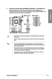
... only, the motherboard may not boot up if the power is inadequate. • If you use a power supply unit (PSU) that complies with ATX 12V Specification 2.0 (or later version) and provides a minimum power of 350 W. • We recommend that you want to fit these connectors in only one orientation. ASUS TUF X299 MARK 1 1-19 The...
... only, the motherboard may not boot up if the power is inadequate. • If you use a power supply unit (PSU) that complies with ATX 12V Specification 2.0 (or later version) and provides a minimum power of 350 W. • We recommend that you want to fit these connectors in only one orientation. ASUS TUF X299 MARK 1 1-19 The...
TUF X299 MARK 1 Users ManualEnglish
Page 39
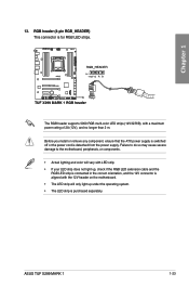
...severe damage to the motherboard, peripherals, or components. • Actual lighting and color will only light up , check if the RGB LED extension cable and the RGB LED strip is connected in the correct orientation, and the 12V connector is purchased separately. ASUS TUF X299 MARK 1 1-23 Chapter ...1 The RGB header supports 5050 RGB multi-color LED strips (12V/G/R/B), with the 12V header on the motherboard. • The LED strip will vary with LED strip. • ...
...severe damage to the motherboard, peripherals, or components. • Actual lighting and color will only light up , check if the RGB LED extension cable and the RGB LED strip is connected in the correct orientation, and the 12V connector is purchased separately. ASUS TUF X299 MARK 1 1-23 Chapter ...1 The RGB header supports 5050 RGB multi-color LED strips (12V/G/R/B), with the 12V header on the motherboard. • The LED strip will vary with LED strip. • ...
TUF X299 MARK 1 Users ManualEnglish
Page 41
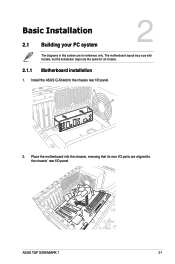
Install the ASUS Q-Shield to the chassis' rear I /O panel. 2. Place the motherboard into the chassis, ensuring that its rear I/O ports are aligned to the chassis rear I /O panel. Chapter 2 ASUS TUF X299 MARK 1 2-1 Chapter 2: Basic Installation Basic Installation 2.1 Building your PC system 2 The diagrams in this section are for all models. 2.1.1 Motherboard installation 1. The motherboard layout may vary with models, but the installation steps are the same for reference only.
Install the ASUS Q-Shield to the chassis' rear I /O panel. 2. Place the motherboard into the chassis, ensuring that its rear I/O ports are aligned to the chassis rear I /O panel. Chapter 2 ASUS TUF X299 MARK 1 2-1 Chapter 2: Basic Installation Basic Installation 2.1 Building your PC system 2 The diagrams in this section are for all models. 2.1.1 Motherboard installation 1. The motherboard layout may vary with models, but the installation steps are the same for reference only.


