

TR-DLS User Manual
Page 1
® TR-DLS Dual Socket 370 Motherboard USER'S MANUAL
® TR-DLS Dual Socket 370 Motherboard USER'S MANUAL

TR-DLS User Manual
Page 4
CONTENTS 1. HARDWARE SETUP 14 3.1 TR-DLS Motherboard Layout 14 3.2 Layout Contents 15 3.3 Hardware Setup Procedure 17 3.4 Motherboard Settings 18 3.4.1 Switches 18 3.4.2 Jumpers 21 3.5 System Memory 23 3.5.1 Memory ...4.2 BIOS Setup Program 45 4.2.1 BIOS Menu Bar 46 4.2.2 Legend Bar 46 4 ASUS TR-DLS User's Manual FEATURES 8 2.1 ASUS TR-DLS Motherboard 8 2.1.1 Specifications 8 2.1.2 Performance 10 2.1.3 Intelligence 11 2.2 TR-DLS Motherboard Components 12 2.2.1 Component Locations 13 3. INTRODUCTION 7 1.1 How This Manual Is Organized 7 1.2 Item Checklist 7...
CONTENTS 1. HARDWARE SETUP 14 3.1 TR-DLS Motherboard Layout 14 3.2 Layout Contents 15 3.3 Hardware Setup Procedure 17 3.4 Motherboard Settings 18 3.4.1 Switches 18 3.4.2 Jumpers 21 3.5 System Memory 23 3.5.1 Memory ...4.2 BIOS Setup Program 45 4.2.1 BIOS Menu Bar 46 4.2.2 Legend Bar 46 4 ASUS TR-DLS User's Manual FEATURES 8 2.1 ASUS TR-DLS Motherboard 8 2.1.1 Specifications 8 2.1.2 Performance 10 2.1.3 Intelligence 11 2.2 TR-DLS Motherboard Components 12 2.2.1 Component Locations 13 3. INTRODUCTION 7 1.1 How This Manual Is Organized 7 1.2 Item Checklist 7...
TR-DLS User Manual
Page 7
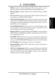
... Instructions on setting up the BIOS 5. APPENDIX Optional items and general reference 1.2 Item Checklist Check that your retailer. (1) ASUS Motherboard (1) I/O Shield (1) Ribbon cable for master and slave IDE drives (1) 68-pin LVD SCSI ribbon cable for Ultra160/320... disk drive (1) Support drivers and utilities (1) Socket 370 CPU Terminator (UMB type) (1) This Motherboard User's Manual ASUS TR-DLS User's Manual 7 1. SOFTWARE SETUP Instructions on setting up the motherboard. 4. If you discover damaged or missing items, contact your package is divided into the following ...
... Instructions on setting up the BIOS 5. APPENDIX Optional items and general reference 1.2 Item Checklist Check that your retailer. (1) ASUS Motherboard (1) I/O Shield (1) Ribbon cable for master and slave IDE drives (1) 68-pin LVD SCSI ribbon cable for Ultra160/320... disk drive (1) Support drivers and utilities (1) Socket 370 CPU Terminator (UMB type) (1) This Motherboard User's Manual ASUS TR-DLS User's Manual 7 1. SOFTWARE SETUP Instructions on setting up the motherboard. 4. If you discover damaged or missing items, contact your package is divided into the following ...

TR-DLS User Manual
Page 8
...Socket 370-based Intel Pentium III Coppermine (256KB L2) and Tualatin (512KB L2) processors running up to provide for additional peripherals 8 ASUS TR-DLS User's Manual FEATURES Specifications 2. Supports PC133 SDRAM with ECC, dual peer to peer PCI buses, and 64-bit 66MHz PCI bus... that supports up to 8MB display SDRAM for server systems that support four IDE devices on two channels. FEATURES 2.1 ASUS TR-DLS Motherboard The ASUS TR-DLS motherboard is designed for 1280x1024 and true color resolutions. • LAN Support: Features Intel 82550 Fast Ethernet LAN controller that...
...Socket 370-based Intel Pentium III Coppermine (256KB L2) and Tualatin (512KB L2) processors running up to provide for additional peripherals 8 ASUS TR-DLS User's Manual FEATURES Specifications 2. Supports PC133 SDRAM with ECC, dual peer to peer PCI buses, and 64-bit 66MHz PCI bus... that supports up to 8MB display SDRAM for server systems that support four IDE devices on two channels. FEATURES 2.1 ASUS TR-DLS Motherboard The ASUS TR-DLS motherboard is designed for 1280x1024 and true color resolutions. • LAN Support: Features Intel 82550 Fast Ethernet LAN controller that...
TR-DLS User Manual
Page 9
.../Floppy boot selection. FEATURES • SMBus: Features the System Management Bus interface, which provides more control and protection over the motherboard. ASUS TR-DLS User's Manual 9 2. FEATURES Optional Components 2. Year 2000 certified. • CPU Throttling: CPU throttling protects CPU from overheating.... enhanced ACPI for Windows NT/2000/XP compatibility, and autodetection of most devices for a separate IOAPIC chip. • ASUS Server Management Card: The optional ASMC-LE and ASMC-ME cards support Intelligent Platform Management Interface (IPMI), system health monitor...
.../Floppy boot selection. FEATURES • SMBus: Features the System Management Bus interface, which provides more control and protection over the motherboard. ASUS TR-DLS User's Manual 9 2. FEATURES Optional Components 2. Year 2000 certified. • CPU Throttling: CPU throttling protects CPU from overheating.... enhanced ACPI for Windows NT/2000/XP compatibility, and autodetection of most devices for a separate IOAPIC chip. • ASUS Server Management Card: The optional ASMC-LE and ASMC-ME cards support Intelligent Platform Management Interface (IPMI), system health monitor...
TR-DLS User Manual
Page 10
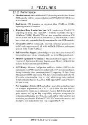
...; Advanced 64-bit PCI: Maximizes IO bandwidth for the next generation of the motherboard meet the stringent requirements for intelligent IO and Server Management cards. • SDRAM Optimized Performance: This motherboard supports PC133 "registered" Synchronous Dynamic Random Access Memory (SDRAM) that older SCSI... the benefits of ACPI, an ACPI-supported OS, such as required by PC '99. 10 ASUS TR-DLS User's Manual Ultra160/320 is also implemented on all ASUS smart series motherboards. The new SDG2.0 requirements for systems and components are not wasted. (Ultra160/320 SCSI cables ...
...; Advanced 64-bit PCI: Maximizes IO bandwidth for the next generation of the motherboard meet the stringent requirements for intelligent IO and Server Management cards. • SDRAM Optimized Performance: This motherboard supports PC133 "registered" Synchronous Dynamic Random Access Memory (SDRAM) that older SCSI... the benefits of ACPI, an ACPI-supported OS, such as required by PC '99. 10 ASUS TR-DLS User's Manual Ultra160/320 is also implemented on all ASUS smart series motherboards. The new SDG2.0 requirements for systems and components are not wasted. (Ultra160/320 SCSI cables ...
TR-DLS User Manual
Page 11
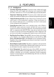
ASUS TR-DLS User's Manual 11 Voltage specifications are used up remotely through an internal or external modem. Suggestions will give the user information on managing their limited ...: To prevent system overheat and system damage, the CPU, power supply, and system fans can be monitored for RPM and failure. FEATURES Intelligence 2. With this motherboard supports processor thermal sensing and auto-protection. • Voltage Monitoring and Alert: System voltage levels are set for future processors, so monitoring is necessary to...
ASUS TR-DLS User's Manual 11 Voltage specifications are used up remotely through an internal or external modem. Suggestions will give the user information on managing their limited ...: To prevent system overheat and system damage, the CPU, power supply, and system fans can be monitored for RPM and failure. FEATURES Intelligence 2. With this motherboard supports processor thermal sensing and auto-protection. • Voltage Monitoring and Alert: System voltage levels are set for future processors, so monitoring is necessary to...

TR-DLS User Manual
Page 12
x 10 in . FEATURES 2.2 TR-DLS Motherboard Components See opposite page for Pentium® III Coppermine and Tualatin™ Processors 2 Chipsets ServerWorks® RCC Champion LE-T North Bridge 4 ServerWorks® ... System Voltage Monitoring (integrated in ASUS ASIC) ....... 12 (4) Fan Power & Speed Monitoring Connectors (see layout on p. 14) Power ATX 24-pin Power Supply Connector 1 Special Features Intelligent Platform Management Interface (IPMI 15 eRMC Connector 16 Onboard LED 14 Form Factor EATX (12 in .) 12 ASUS TR-DLS User's Manual Location Processor Support ...
x 10 in . FEATURES 2.2 TR-DLS Motherboard Components See opposite page for Pentium® III Coppermine and Tualatin™ Processors 2 Chipsets ServerWorks® RCC Champion LE-T North Bridge 4 ServerWorks® ... System Voltage Monitoring (integrated in ASUS ASIC) ....... 12 (4) Fan Power & Speed Monitoring Connectors (see layout on p. 14) Power ATX 24-pin Power Supply Connector 1 Special Features Intelligent Platform Management Interface (IPMI 15 eRMC Connector 16 Onboard LED 14 Form Factor EATX (12 in .) 12 ASUS TR-DLS User's Manual Location Processor Support ...

TR-DLS User Manual
Page 14
HARDWARE SETUP 3.1 TR-DLS Motherboard Layout PS/2 T: Mouse B: Keyboard Bottom: Top: USB1 RJ-45 ... Socket 3 (72-bit, 168-pin module) CHA_FAN2 PGA 370 PARALLEL PORT ATX_POWER KBPWR COM2 CHASSIS USBPORT TR-DLS ServerWorks® RCC LE-T North Bridge CPU_FAN2 PGA 370 VGA CR2032 3V Lithium Cell CMOS Power 01 23...ASUS ASIC PCI6 (32-bit, 33MHz 5V) with Hardware Monitor BPSMB Primary IDE1 Secondary IDE2 eRMC CONNECTOR IPMI FLOPPY PANEL HD_LED NOTE: The SCSI and ASMC features, eRMC connector, and IPMI connectors are grayed out in the above motherboard layout. 14 ASUS TR-DLS...
HARDWARE SETUP 3.1 TR-DLS Motherboard Layout PS/2 T: Mouse B: Keyboard Bottom: Top: USB1 RJ-45 ... Socket 3 (72-bit, 168-pin module) CHA_FAN2 PGA 370 PARALLEL PORT ATX_POWER KBPWR COM2 CHASSIS USBPORT TR-DLS ServerWorks® RCC LE-T North Bridge CPU_FAN2 PGA 370 VGA CR2032 3V Lithium Cell CMOS Power 01 23...ASUS ASIC PCI6 (32-bit, 33MHz 5V) with Hardware Monitor BPSMB Primary IDE1 Secondary IDE2 eRMC CONNECTOR IPMI FLOPPY PANEL HD_LED NOTE: The SCSI and ASMC features, eRMC connector, and IPMI connectors are grayed out in the above motherboard layout. 14 ASUS TR-DLS...

TR-DLS User Manual
Page 15
HARDWARE SETUP 3.2 Layout Contents Motherboard Settings 1) CLKSW p. 18 CPU Bus Frequency Setting 2) CONFIG p. 19 CPU Core Bus Frequency Multiplier 3) SCSIEN p. 21 SCSI Setting 4) VGAEN p. 21 VGA Setting 5) KBPWR p. 22 Keyboard ... p. 36 SMBus Connectors (two 6-1 pins) 10 USBPORT p. 36 Universal Serial Port Header (10-1pin male) 11) ATXPWR p. 37 ATX Power Supply Connector (20/24-pin) ASUS TR-DLS User's Manual 15 3. H/W SETUP Layout Contents 3.
HARDWARE SETUP 3.2 Layout Contents Motherboard Settings 1) CLKSW p. 18 CPU Bus Frequency Setting 2) CONFIG p. 19 CPU Core Bus Frequency Multiplier 3) SCSIEN p. 21 SCSI Setting 4) VGAEN p. 21 VGA Setting 5) KBPWR p. 22 Keyboard ... p. 36 SMBus Connectors (two 6-1 pins) 10 USBPORT p. 36 Universal Serial Port Header (10-1pin male) 11) ATXPWR p. 37 ATX Power Supply Connector (20/24-pin) ASUS TR-DLS User's Manual 15 3. H/W SETUP Layout Contents 3.

TR-DLS User Manual
Page 16
3. H/W SETUP Motherboard Settings 16 ASUS TR-DLS User's Manual HARDWARE SETUP 12) eRMC p. 37 ASUS Server Management Card Connector (50-pin) 13) IPMI p. 38 Intelligent Platform Management Interface (4-pin) 14) NIC (PANEL) p. 38 NIC Activity LED (2-pin) 15) STATUS (PANEL) p. ...
3. H/W SETUP Motherboard Settings 16 ASUS TR-DLS User's Manual HARDWARE SETUP 12) eRMC p. 37 ASUS Server Management Card Connector (50-pin) 13) IPMI p. 38 Intelligent Platform Management Interface (4-pin) 14) NIC (PANEL) p. 38 NIC Activity LED (2-pin) 15) STATUS (PANEL) p. ...

TR-DLS User Manual
Page 17
... the ICs on a grounded antistatic pad or in soft-off or the power cord is detached from the wall socket before touching any motherboard settings. 1. HARDWARE SETUP 3.3 Hardware Setup Procedure Complete the following precautions before using your computer: 1. Install a CPU terminator, if you... safely grounded object, such as the power supply case, before you installed only one CPU. 5. H/W SETUP Motherboard Settings TR-DLS TR-DLS Onboard LED LED1 ON Standby Power OFF Powered Off ASUS TR-DLS User's Manual 17 3. Make sure that the LED is either ON, in sleep mode, or in the...
... the ICs on a grounded antistatic pad or in soft-off or the power cord is detached from the wall socket before touching any motherboard settings. 1. HARDWARE SETUP 3.3 Hardware Setup Procedure Complete the following precautions before using your computer: 1. Install a CPU terminator, if you... safely grounded object, such as the power supply case, before you installed only one CPU. 5. H/W SETUP Motherboard Settings TR-DLS TR-DLS Onboard LED LED1 ON Standby Power OFF Powered Off ASUS TR-DLS User's Manual 17 3. Make sure that the LED is either ON, in sleep mode, or in the...

TR-DLS User Manual
Page 18
... frequency multiple equals the CPU internal frequency (the advertised CPU speed). The white block on the motherboard and the function of each switch. TR-DLS TR-DLS DIP Switches CLKSW ON OFF ON 12345 CONFIG ON 12345678 1. Frequency Selection 4. Reserved 2. Frequency... CLKSW TR-DLS ON ON CPU 12345 100MHz 12345 133MHz TR-DLS CPU External Frequency Selection CAUTION! Frequency Multiple ON OFF 1. Frequencies other than the recommended CPU bus frequencies are not guaranteed to be stable. 18 ASUS TR-DLS User's Manual HARDWARE SETUP 3.4 Motherboard Settings ...
... frequency multiple equals the CPU internal frequency (the advertised CPU speed). The white block on the motherboard and the function of each switch. TR-DLS TR-DLS DIP Switches CLKSW ON OFF ON 12345 CONFIG ON 12345678 1. Frequency Selection 4. Reserved 2. Frequency... CLKSW TR-DLS ON ON CPU 12345 100MHz 12345 133MHz TR-DLS CPU External Frequency Selection CAUTION! Frequency Multiple ON OFF 1. Frequencies other than the recommended CPU bus frequencies are not guaranteed to be stable. 18 ASUS TR-DLS User's Manual HARDWARE SETUP 3.4 Motherboard Settings ...

TR-DLS User Manual
Page 20
... CPU core bus frequency settings for Pentium III Tualatin CPU. TR-DLS ON 12345678 ON: Enable OFF: Disable TR-DLS External Buzzer Setting External Buzzer 20 ASUS TR-DLS User's Manual Set to ON to activate the external buzzer. Set to OFF to disable the buzzer. H/W SETUP Motherboard Settings 3. 3. Tualatin ON 12345678 ON 12345678 ON 12345678 ON 12345678...
... CPU core bus frequency settings for Pentium III Tualatin CPU. TR-DLS ON 12345678 ON: Enable OFF: Disable TR-DLS External Buzzer Setting External Buzzer 20 ASUS TR-DLS User's Manual Set to ON to activate the external buzzer. Set to OFF to disable the buzzer. H/W SETUP Motherboard Settings 3. 3. Tualatin ON 12345678 ON 12345678 ON 12345678 ON 12345678...

TR-DLS User Manual
Page 21
IMPORTANT! Set to Disable (pins (2-3) if you to use SCSI devices. TR-DLS TR-DLS SCSI Setting SCSIEN 2 1 Enable (Default) 3 2 Disable 2. TR-DLS TR-DLS VGA Setting VGAEN 12 Enable (Default) 23 Disable ASUS TR-DLS User's Manual 21 Set to Enable (pins 1-2) if you wish to enable or disable the onboard VGA.... VGA Settings (3-pin VGAEN) This jumper allows you install a VGA card. HARDWARE SETUP 3.4.2 Jumpers The jumpers on the motherboard allow you to use the onboard VGA capability. SCSI Settings (3-pin SCSIEN) This jumper allows you to change some feature settings...
IMPORTANT! Set to Disable (pins (2-3) if you to use SCSI devices. TR-DLS TR-DLS SCSI Setting SCSIEN 2 1 Enable (Default) 3 2 Disable 2. TR-DLS TR-DLS VGA Setting VGAEN 12 Enable (Default) 23 Disable ASUS TR-DLS User's Manual 21 Set to Enable (pins 1-2) if you wish to enable or disable the onboard VGA.... VGA Settings (3-pin VGAEN) This jumper allows you install a VGA card. HARDWARE SETUP 3.4.2 Jumpers The jumpers on the motherboard allow you to use the onboard VGA capability. SCSI Settings (3-pin SCSIEN) This jumper allows you to change some feature settings...

TR-DLS User Manual
Page 22
...allow you to Clear CMOS PCI3 (32-bit, 33MHz 5V) PCI4 (32-bit, 33MHz 5V) TR-DLS Clear RTC RAM 22 ASUS TR-DLS User's Manual Plug the power cord and turn ON the computer. 6. TR-DLS CLRCMOS Short solder points to clear the RTC RAM in the BIOS (see section 4.5.1 Power Up ...is powered by erasing the CMOS Real Time Clock (RTC) RAM. You can supply at least 1A on the keyboard. H/W SETUP Motherboard Settings TR-DLS KBPWR 2 1 5V (Default) 3 2 5VSB TR-DLS Keyboard Power Setting 4. Turn OFF the computer and unplug the power cord. 2. To erase the RTC RAM: 1. Short the solder...
...allow you to Clear CMOS PCI3 (32-bit, 33MHz 5V) PCI4 (32-bit, 33MHz 5V) TR-DLS Clear RTC RAM 22 ASUS TR-DLS User's Manual Plug the power cord and turn ON the computer. 6. TR-DLS CLRCMOS Short solder points to clear the RTC RAM in the BIOS (see section 4.5.1 Power Up ...is powered by erasing the CMOS Real Time Clock (RTC) RAM. You can supply at least 1A on the keyboard. H/W SETUP Motherboard Settings TR-DLS KBPWR 2 1 5V (Default) 3 2 5VSB TR-DLS Keyboard Power Setting 4. Turn OFF the computer and unplug the power cord. 2. To erase the RTC RAM: 1. Short the solder...

TR-DLS User Manual
Page 23
HARDWARE SETUP 3.5 System Memory This motherboard uses only Dual Inline Memory Modules (DIMMs). One side (with memory chips) of the DIMM takes up to use the specified DIMM types for 3.3Volt (... and Correction (ECC). Make sure to 4GB. The motherboard supports a memory configuration of up one row on the motherboard. 3.5.1 Memory Configurations Install memory in any of 16MB, 32MB, 64MB, 128MB, 256MB, 512MB, or 1GB densities with ECC. Four DIMM sockets are available for smooth system operation. 3. H/W SETUP System Memory ASUS TR-DLS User's Manual 23 3.
HARDWARE SETUP 3.5 System Memory This motherboard uses only Dual Inline Memory Modules (DIMMs). One side (with memory chips) of the DIMM takes up to use the specified DIMM types for 3.3Volt (... and Correction (ECC). Make sure to 4GB. The motherboard supports a memory configuration of up one row on the motherboard. 3.5.1 Memory Configurations Install memory in any of 16MB, 32MB, 64MB, 128MB, 256MB, 512MB, or 1GB densities with ECC. Four DIMM sockets are available for smooth system operation. 3. H/W SETUP System Memory ASUS TR-DLS User's Manual 23 3.

TR-DLS User Manual
Page 24
...DIMM type, check the notches on either side of the breaks, the module only fits in one direction. This motherboard supports four clock signals per DIMM. 24 ASUS TR-DLS User's Manual Failure to do so may cause severe damage to prevent the wrong type from being inserted into ... Hardware Setup Procedure for more information). Insert a DIMM into the DIMM slot on each side. SDRAM DIMMs have different pin contacts on the motherboard. You must tell your retailer the correct DIMM type before purchasing. H/W SETUP System Memory The notches on the DIMM shifts between left, center,...
...DIMM type, check the notches on either side of the breaks, the module only fits in one direction. This motherboard supports four clock signals per DIMM. 24 ASUS TR-DLS User's Manual Failure to do so may cause severe damage to prevent the wrong type from being inserted into ... Hardware Setup Procedure for more information). Insert a DIMM into the DIMM slot on each side. SDRAM DIMMs have different pin contacts on the motherboard. You must tell your retailer the correct DIMM type before purchasing. H/W SETUP System Memory The notches on the DIMM shifts between left, center,...

TR-DLS User Manual
Page 25
... Pentium III Coppermine (256KB L2) and Tualatin (512KB L2) CPUs running up to avoid start-up problems. 3. H/W SETUP CPU ASUS TR-DLS User's Manual 25 The following illustration shows the location of the CPU and terminator with a dual Socket 370 for the processor to ... Multiple (frequency multiple setting is installed) TR-DLS Socket 370 Silver Arrow Note in the illustration that you to damage the CPU pins. HARDWARE SETUP 3.6 Central Processing Unit (CPU) The motherboard comes with the corresponding corner on the motherboard and the correct CPU and terminator orientation...
... Pentium III Coppermine (256KB L2) and Tualatin (512KB L2) CPUs running up to avoid start-up problems. 3. H/W SETUP CPU ASUS TR-DLS User's Manual 25 The following illustration shows the location of the CPU and terminator with a dual Socket 370 for the processor to ... Multiple (frequency multiple setting is installed) TR-DLS Socket 370 Silver Arrow Note in the illustration that you to damage the CPU pins. HARDWARE SETUP 3.6 Central Processing Unit (CPU) The motherboard comes with the corresponding corner on the motherboard and the correct CPU and terminator orientation...

TR-DLS User Manual
Page 26
... that the CPU is in place, press it fits in one orientation. The figure on the motherboard. 2. Carefully insert the CPU into the socket to a 90°-100° angle. 3. It will cause system damage! 26 ASUS TR-DLS User's Manual Locate the ZIF socket on the right shows an installed CPU terminator. If...
... that the CPU is in place, press it fits in one orientation. The figure on the motherboard. 2. Carefully insert the CPU into the socket to a 90°-100° angle. 3. It will cause system damage! 26 ASUS TR-DLS User's Manual Locate the ZIF socket on the right shows an installed CPU terminator. If...

