T2-R User Manual
Page 3
... components 19 1.6 LED panel 20 Chapter 2: Basic installation 2.1 Preparation 22 2.2 Before you proceed 22 2.3 Removing the cover 23 2.4 Removing the power supply 24 2.5 Installing a CPU 25 2.5.1 Removing the CPU fan and heatsink assembly .... 25 2.5.2 CPU installation 26 2.5.3 Re-installing the CPU fan ...32 2.8 Installing a second optical drive 33 2.9 Installing a hard disk drive 35 2.10 Re-installing the power supply unit 37 2.10.1 Voltage selector 38 2.10.2 Power supply specifications 39 2.11 Replacing the cover 40 2.12 Connecting external devices 41 To the front panel 41 To...
... components 19 1.6 LED panel 20 Chapter 2: Basic installation 2.1 Preparation 22 2.2 Before you proceed 22 2.3 Removing the cover 23 2.4 Removing the power supply 24 2.5 Installing a CPU 25 2.5.1 Removing the CPU fan and heatsink assembly .... 25 2.5.2 CPU installation 26 2.5.3 Re-installing the CPU fan ...32 2.8 Installing a second optical drive 33 2.9 Installing a hard disk drive 35 2.10 Re-installing the power supply unit 37 2.10.1 Voltage selector 38 2.10.2 Power supply specifications 39 2.11 Replacing the cover 40 2.12 Connecting external devices 41 To the front panel 41 To...

T2-R User Manual
Page 7
... technician or your retailer. Operation safety • Before installing devices into the system, carefully read all cables are correctly connected and the power cables are connected. • If the power supply is incorrectly replaced. VORSICHT: Explosionsgetahr bei unsachgemäßen Austausch der Batterie. Dispose of explosion if battery is broken, do not...
... technician or your retailer. Operation safety • Before installing devices into the system, carefully read all cables are correctly connected and the power cables are connected. • If the power supply is incorrectly replaced. VORSICHT: Explosionsgetahr bei unsachgemäßen Austausch der Batterie. Dispose of explosion if battery is broken, do not...

T2-R User Manual
Page 18
...18 Chapter 1: System introduction Gigabit LAN port. (Commercial Deluxe models only.) This port allows high-speed connection to a Local Area Network (LAN) through a network hub. 14. 8. Microphone port. Ethernet LAN port. Power supply unit fan. This fan provides ventilation inside the system ...This Microphone (pink) port connects a microphone. This switch allows you to select the appropriate voltage supply in your area. This fan provides ventilation inside the power supply unit. 18. See the "Voltage selector" section on page 38 before adjusting this cover when ...
...18 Chapter 1: System introduction Gigabit LAN port. (Commercial Deluxe models only.) This port allows high-speed connection to a Local Area Network (LAN) through a network hub. 14. 8. Microphone port. Ethernet LAN port. Power supply unit fan. This fan provides ventilation inside the system ...This Microphone (pink) port connects a microphone. This switch allows you to select the appropriate voltage supply in your area. This fan provides ventilation inside the power supply unit. 18. See the "Voltage selector" section on page 38 before adjusting this cover when ...
T2-R User Manual
Page 19
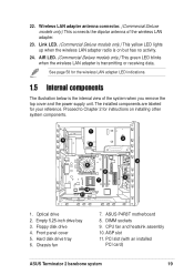
Proceed to Chapter 2 for your reference. Chassis fan 7. Link LED. (Commercial Deluxe models only.) This yellow LED lights up when the wireless LAN adapter radio is the internal view of the wireless LAN adapter. 23. Optical ... installed PCI card) ASUS Terminator 2 barebone system 19 DIMM sockets 9. AGP slot 11. CPU fan and heatsink assembly 10. Wireless LAN adapter antenna connector. (Commercial Deluxe models only.) This connects the dipolar antenna of the system when you remove the top cover and the power supply unit. AIR LED. (Commercial Deluxe models only.) This ...
Proceed to Chapter 2 for your reference. Chassis fan 7. Link LED. (Commercial Deluxe models only.) This yellow LED lights up when the wireless LAN adapter radio is the internal view of the wireless LAN adapter. 23. Optical ... installed PCI card) ASUS Terminator 2 barebone system 19 DIMM sockets 9. AGP slot 11. CPU fan and heatsink assembly 10. Wireless LAN adapter antenna connector. (Commercial Deluxe models only.) This connects the dipolar antenna of the system when you remove the top cover and the power supply unit. AIR LED. (Commercial Deluxe models only.) This ...
T2-R User Manual
Page 22
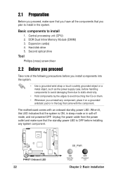
... and make sure that you have all the components that you uninstall any system component. ® P4R8T P4R8T Onboard LED 22 SB_PWR ON Standby Power OFF Powered Off Chapter 2: Basic installation Expansion card(s) 4. When lit, this LED indicates that the system is OFF before handling components to avoid damaging them... before you install components into the system. • Use a grounded wrist strap or touch a safely grounded object or a metal object, such as the power supply case, before installing any component, place it on them. • Whenever you plan to install 1.
... and make sure that you have all the components that you uninstall any system component. ® P4R8T P4R8T Onboard LED 22 SB_PWR ON Standby Power OFF Powered Off Chapter 2: Basic installation Expansion card(s) 4. When lit, this LED indicates that the system is OFF before handling components to avoid damaging them... before you install components into the system. • Use a grounded wrist strap or touch a safely grounded object or a metal object, such as the power supply case, before installing any component, place it on them. • Whenever you plan to install 1.

T2-R User Manual
Page 24
...secures the PSU to the left until the side hook is disengaged from the chassis. 5. Disconnect the power plugs on a flat, stable surface. 2. Disconnect the optical drive and floppy disk drive power plugs. 3. Lift the PSU slightly. 5 7. Slide the PSU to the chassis. 3 4. Set ... inch. 6. The unit might accidentally drop and 7 damage the other system components. To remove the PSU: 1. 2.4 Removing the power supply You must remove the power supply unit (PSU) before you can install a central processing unit (CPU) and other system components. 24 Chapter 2: Basic installation
...secures the PSU to the left until the side hook is disengaged from the chassis. 5. Disconnect the power plugs on a flat, stable surface. 2. Disconnect the optical drive and floppy disk drive power plugs. 3. Lift the PSU slightly. 5 7. Slide the PSU to the chassis. 3 4. Set ... inch. 6. The unit might accidentally drop and 7 damage the other system components. To remove the PSU: 1. 2.4 Removing the power supply You must remove the power supply unit (PSU) before you can install a central processing unit (CPU) and other system components. 24 Chapter 2: Basic installation

T2-R User Manual
Page 34
...Deluxe models, re-connect the LED panel and the front 13 audio button panel cables to the 4-pin connector at the back of the IDE ribbon cable to the secondary IDE connector (black connector labeled SEC_IDE) on the motherboard. Connect the other end of the optical drive. Connect a power cable from the power supply... unit to the 4-pin CD1 connector on the motherboard. Connect the other end of the audio cable to the power connector at the back of the secondary IDE connector. 12....
...Deluxe models, re-connect the LED panel and the front 13 audio button panel cables to the 4-pin connector at the back of the IDE ribbon cable to the secondary IDE connector (black connector labeled SEC_IDE) on the motherboard. Connect the other end of the optical drive. Connect a power cable from the power supply... unit to the 4-pin CD1 connector on the motherboard. Connect the other end of the audio cable to the power connector at the back of the secondary IDE connector. 12....

T2-R User Manual
Page 36
Connect a 4-pin power plug from the power supply unit to the chassis hooks. 6 7. Connect the other end of the 9 IDE ribbon cable to the IDE connector on the motherboard. Secure the tray with the screw you removed earlier . 7 8. Connect one end of the primary IDE connector. 36 Chapter 2: Basic installation Re-install the HDD tray and HDD inside the chassis by loching the tray slots to the HDD power connector. 8 10. 6. See page 76 for the location of the 40-pin IDE cable to the primary IDE connector (blue connector labeled PRI_IDE) on the drive. 9.
Connect a 4-pin power plug from the power supply unit to the chassis hooks. 6 7. Connect the other end of the 9 IDE ribbon cable to the IDE connector on the motherboard. Secure the tray with the screw you removed earlier . 7 8. Connect one end of the primary IDE connector. 36 Chapter 2: Basic installation Re-install the HDD tray and HDD inside the chassis by loching the tray slots to the HDD power connector. 8 10. 6. See page 76 for the location of the 40-pin IDE cable to the primary IDE connector (blue connector labeled PRI_IDE) on the drive. 9.
T2-R User Manual
Page 37
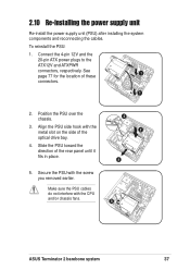
2.10 Re-installing the power supply unit Re-install the power supply unit (PSU) after installing the system components and reconnecting the cables. Align the PSU side hook with the metal slot on the side of the ... place. 3 2 4 5. Position the PSU over the chassis. 3. Connect the 4-pin 12V and the 20-pin ATX power plugs to the ATX12V and ATXPWR connectors, respectively. Secure the PSU with the CPU and/or chassis fans. 5 ASUS Terminator 2 barebone system 37 Slide the PSU toward the direction of the optical drive bay. 4. Make sure...
2.10 Re-installing the power supply unit Re-install the power supply unit (PSU) after installing the system components and reconnecting the cables. Align the PSU side hook with the metal slot on the side of the ... place. 3 2 4 5. Position the PSU over the chassis. 3. Connect the 4-pin 12V and the 20-pin ATX power plugs to the ATX12V and ATXPWR connectors, respectively. Secure the PSU with the CPU and/or chassis fans. 5 ASUS Terminator 2 barebone system 37 Slide the PSU toward the direction of the optical drive bay. 4. Make sure...

T2-R User Manual
Page 38
... 230V. Use this switch to select the appropriate voltage according to the power connector of the optical drive(s). 8. If the voltage supply in your area is set to the power connector of the floppy disk drive. 7. 7 8 Power supply unit plugs 1 1 6 6. If the voltage supply in a 230V environment will seriously damage the system! 230 38 Chapter 2: Basic...
... 230V. Use this switch to select the appropriate voltage according to the power connector of the optical drive(s). 8. If the voltage supply in your area is set to the power connector of the floppy disk drive. 7. 7 8 Power supply unit plugs 1 1 6 6. If the voltage supply in a 230V environment will seriously damage the system! 230 38 Chapter 2: Basic...
T2-R User Manual
Page 39
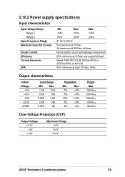
2.10.2 Power supply specifications Input characteristics Input Voltage Range Range 1 Range 2 Input Frequency Range Maximum Input AC Current Inrush Current Efficiency Current Harmonic EPA Min Nom Max 90V ... Max -5% +5% -5% +5% -10% +10% -5% +5% -5% +5% Ripple Max 50mVp-p 120mVp-p 150mVp-p 60mVp-p 60mVp-p Over-Voltage Protection (OVP) Output Voltage +3.3V +5V +12V Maximum Voltage 4.6V 6.5V 15.6V ASUS Terminator 2 barebone system 39
2.10.2 Power supply specifications Input characteristics Input Voltage Range Range 1 Range 2 Input Frequency Range Maximum Input AC Current Inrush Current Efficiency Current Harmonic EPA Min Nom Max 90V ... Max -5% +5% -5% +5% -10% +10% -5% +5% -5% +5% Ripple Max 50mVp-p 120mVp-p 150mVp-p 60mVp-p 60mVp-p Over-Voltage Protection (OVP) Output Voltage +3.3V +5V +12V Maximum Voltage 4.6V 6.5V 15.6V ASUS Terminator 2 barebone system 39

T2-R User Manual
Page 77
...provided floppy drive ribbon cable. FLOPPY PIN 1 ® P4R8T NOTE: Orient the red markings on the power supply unit. Find the proper orientation and push down firmly until the connectors fit completely. Connect one orientation. ATXPWR +12.0Volts +5V ...Ground +3.3 Volts +3.3 Volts +5.0 Volts +5.0 Volts -5.0 Volts Ground Ground Ground Power Supply On Ground -12.0Volts +3.3Volts ® P4R8T P4R8T ATX Power Connector ATX12V +12V DC COM +12V DC COM ASUS Terminator 2 barebone system 77 7. ATX power connectors (20-pin ATXPWR, 4-pin ATX12V) These connectors are designed to ...
...provided floppy drive ribbon cable. FLOPPY PIN 1 ® P4R8T NOTE: Orient the red markings on the power supply unit. Find the proper orientation and push down firmly until the connectors fit completely. Connect one orientation. ATXPWR +12.0Volts +5V ...Ground +3.3 Volts +3.3 Volts +5.0 Volts +5.0 Volts -5.0 Volts Ground Ground Ground Power Supply On Ground -12.0Volts +3.3Volts ® P4R8T P4R8T ATX Power Connector ATX12V +12V DC COM +12V DC COM ASUS Terminator 2 barebone system 77 7. ATX power connectors (20-pin ATXPWR, 4-pin ATX12V) These connectors are designed to ...

T2-R User Manual
Page 79
...you turn on the BIOS or OS settings. ASUS Terminator 2 barebone system 79 USB card reader connector (10-1 pin USB56) This connector supports the storage card reader. IDE_LED Power LED IDE_LED- USB56 GND USBP3+ USBP3USB Power ® P4R8T P4R8T USB Card Reader Connector... USBP2USB Power 10 6 5 1 12. Pressing the power switch while in sleep mode. • ATX Power Switch This connector connects a switch that controls the system power. PLED+ PANEL Ground PWR ® P4R8T P4R8T System Panel Connector ATX Power Switch* * Requires an ATX power supply. • Power LED ...
...you turn on the BIOS or OS settings. ASUS Terminator 2 barebone system 79 USB card reader connector (10-1 pin USB56) This connector supports the storage card reader. IDE_LED Power LED IDE_LED- USB56 GND USBP3+ USBP3USB Power ® P4R8T P4R8T USB Card Reader Connector... USBP2USB Power 10 6 5 1 12. Pressing the power switch while in sleep mode. • ATX Power Switch This connector connects a switch that controls the system power. PLED+ PANEL Ground PWR ® P4R8T P4R8T System Panel Connector ATX Power Switch* * Requires an ATX power supply. • Power LED ...

T2-R User Manual
Page 80
The read or write activities of any device connected to the primary or secondary IDE connector cause this LED to the hard disk drive activity LED. • IDE LED Lead This 2-pin connector supplies power to light up. 80 Chapter 4: Motherboard info
The read or write activities of any device connected to the primary or secondary IDE connector cause this LED to the hard disk drive activity LED. • IDE LED Lead This 2-pin connector supplies power to light up. 80 Chapter 4: Motherboard info

T2-R User Manual
Page 106
When this item is set to turn on the system. This feature requires an ATX power supply that provides at least 1A on the +5VSB lead. Configuration options: [Power Off] [Power On] Power On with PS/2 Mouse [Disabled] This parameter allows you to use specific keys on ...Chapter 5: BIOS setup Restore on AC Power Loss [Power Off] When set to turn on the system. This feature requires an ATX power supply that provides at least 1A on the +5VSB lead. 5.5.5 APM Configuration Restore on AC Power Loss Power on with PS/2 Keyboard Power on with set values. Configuration options:...
When this item is set to turn on the system. This feature requires an ATX power supply that provides at least 1A on the +5VSB lead. Configuration options: [Power Off] [Power On] Power On with PS/2 Mouse [Disabled] This parameter allows you to use specific keys on ...Chapter 5: BIOS setup Restore on AC Power Loss [Power Off] When set to turn on the system. This feature requires an ATX power supply that provides at least 1A on the +5VSB lead. 5.5.5 APM Configuration Restore on AC Power Loss Power on with PS/2 Keyboard Power on with set values. Configuration options:...


