
User Manual
Page 31
ok A:\> 當 BIOS DOS 31 exe 2 DOS afudos /o[filename filename A:\>afudos /oOLDBIOS1.rom 3. 按下 afudos /oOLDBIOS1.rom AMI Firmware Update Utility - All rights reserved. done Write to file...... Version 1.19(ASUS V2.07(03.11.24BB)) Copyright (C) 2002 American Megatrends, Inc. Reading flash ..... BIOS 2.1 使用 AFUDOS BIOS AFUDOS DOS BIOS BIOS 程式。AFUDOS BIOS BIOS BIOS 程式 BIOS 程式。 1.2MB BIOS 1 AFUDOS 程式(afudos.
ok A:\> 當 BIOS DOS 31 exe 2 DOS afudos /o[filename filename A:\>afudos /oOLDBIOS1.rom 3. 按下 afudos /oOLDBIOS1.rom AMI Firmware Update Utility - All rights reserved. done Write to file...... Version 1.19(ASUS V2.07(03.11.24BB)) Copyright (C) 2002 American Megatrends, Inc. Reading flash ..... BIOS 2.1 使用 AFUDOS BIOS AFUDOS DOS BIOS BIOS 程式。AFUDOS BIOS BIOS BIOS 程式 BIOS 程式。 1.2MB BIOS 1 AFUDOS 程式(afudos.

User Manual
Page 32
... American Megatrends, Inc. done Writing flash ...... done Reading flash ...... 更新 BIOS 程式 AFUDOS BIOS 程式。 1 tw.asus.com BIOS 片中。 BIOS BIOS 2. 將 AFUDOS.EXE BIOS 3 DOS afudos /i[filename filename BIOS 程式。 A:\>afudos /iP5B-VM DO.ROM 4. AFUDOS BIOS 程式。 A:\>afudos /iP5B-VM DO.ROM AMI Firmware Update Utility...
... American Megatrends, Inc. done Writing flash ...... done Reading flash ...... 更新 BIOS 程式 AFUDOS BIOS 程式。 1 tw.asus.com BIOS 片中。 BIOS BIOS 2. 將 AFUDOS.EXE BIOS 3 DOS afudos /i[filename filename BIOS 程式。 A:\>afudos /iP5B-VM DO.ROM 4. AFUDOS BIOS 程式。 A:\>afudos /iP5B-VM DO.ROM AMI Firmware Update Utility...

User Manual
Page 33
... 程式(AWDFLASH.EXE BIOS AwardBIOS Flash BIOS 程式。 1 http://tw.asus.com BIOS M2N-VM HDMI.bin FAT 32/16 格式的 USB BIOS 2 CD/DVD AwardBIOS Flash BIOS 3 DOS 4. 當 A BIOS 檔案與 AwardBIOS Flash 5 A awdflash 並按下 鍵。 AwardBIOS Flash Utility for ASUS V1.14 (C) Phoenix Technologies Ltd...
... 程式(AWDFLASH.EXE BIOS AwardBIOS Flash BIOS 程式。 1 http://tw.asus.com BIOS M2N-VM HDMI.bin FAT 32/16 格式的 USB BIOS 2 CD/DVD AwardBIOS Flash BIOS 3 DOS 4. 當 A BIOS 檔案與 AwardBIOS Flash 5 A awdflash 並按下 鍵。 AwardBIOS Flash Utility for ASUS V1.14 (C) Phoenix Technologies Ltd...

User Manual
Page 34
... Write OK No Update Write Fail Warning: Don't Turn Off Power Or Reset System! 在更新 BIOS 9 Flash Complete BIOS F1 AwardBIOS Flash Utility for ASUS V1.14 (C) Phoenix Technologies Ltd. 7 BIOS N BIOS 8 BIOS BIOS AwardBIOS Flash Utility for ASUS V1.14 (C) Phoenix Technologies Ltd. All Rights Reserved For C51PV-MCP51-M2A-VM HDMI-00 DATE:04...
... Write OK No Update Write Fail Warning: Don't Turn Off Power Or Reset System! 在更新 BIOS 9 Flash Complete BIOS F1 AwardBIOS Flash Utility for ASUS V1.14 (C) Phoenix Technologies Ltd. 7 BIOS N BIOS 8 BIOS BIOS AwardBIOS Flash Utility for ASUS V1.14 (C) Phoenix Technologies Ltd. All Rights Reserved For C51PV-MCP51-M2A-VM HDMI-00 DATE:04...

User Manual
Page 4
... the computer 3-2 3.2.1 Using the OS shut down function 3-2 3.2.2 Using the dual function power switch 3-2 Chapter 4: BIOS setup 4.1 Managing and updating your BIOS 4-1 4.1.1 ASUS Update utility 4-1 4.1.2 ASUS EZ Flash 2 utility 4-4 4.1.3 Updating the BIOS 4-5 4.1.4 Saving the current BIOS file 4-7 4.1.5 ASUS CrashFree BIOS utility 4-8 4.2 BIOS setup program 4-9 4.2.1 BIOS menu screen 4-10 4.2.2 Menu bar 4-10 4.2.3 Legend bar 4-11 4.2.4 Menu items 4-11 4.2.5 Sub-menu items...
... the computer 3-2 3.2.1 Using the OS shut down function 3-2 3.2.2 Using the dual function power switch 3-2 Chapter 4: BIOS setup 4.1 Managing and updating your BIOS 4-1 4.1.1 ASUS Update utility 4-1 4.1.2 ASUS EZ Flash 2 utility 4-4 4.1.3 Updating the BIOS 4-5 4.1.4 Saving the current BIOS file 4-7 4.1.5 ASUS CrashFree BIOS utility 4-8 4.2 BIOS setup program 4-9 4.2.1 BIOS menu screen 4-10 4.2.2 Menu bar 4-10 4.2.3 Legend bar 4-11 4.2.4 Menu items 4-11 4.2.5 Sub-menu items...

User Manual
Page 10
...procedures that you need when installing and configuring the motherboard. How this guide This user guide contains the information you have been added by your dealer. ASUS websites The ASUS website provides updated information on the motherboard. • Chapter 3: Powering up This chapter ... of the switches, jumpers, and connectors on ASUS hardware and software products. Detailed descriptions of the BIOS parameters are not part of shutting down the system. • Chapter 4: BIOS setup This chapter tells how to the ASUS contact information. 2. About this guide is organized...
...procedures that you need when installing and configuring the motherboard. How this guide This user guide contains the information you have been added by your dealer. ASUS websites The ASUS website provides updated information on the motherboard. • Chapter 3: Powering up This chapter ... of the switches, jumpers, and connectors on ASUS hardware and software products. Detailed descriptions of the BIOS parameters are not part of shutting down the system. • Chapter 4: BIOS setup This chapter tells how to the ASUS contact information. 2. About this guide is organized...

User Manual
Page 13
... (4 ports at midboard, 6 ports at rear panel) ASUS Q-Connector ASUS Q-Fan Plus ASUS EZ Flash 2 ASUS CrashFree BIOS ROG BIOS Wallpaper ASUS MyLogo 3™ 1 x PS/2 Keyboard (purple) 1 x S/PDIF Out (Coaxial + Optical) 2 x External SATA ports 1 x IEEE1394a port 2 x LAN (RJ45) ports 6 x USB 2.0/1.1 ports 1 x Clr CMOS switch (continued on the next page) xiii Striker II Extreme / Striker II NSE specifications summary IEEE 1394 USB ROG...
... (4 ports at midboard, 6 ports at rear panel) ASUS Q-Connector ASUS Q-Fan Plus ASUS EZ Flash 2 ASUS CrashFree BIOS ROG BIOS Wallpaper ASUS MyLogo 3™ 1 x PS/2 Keyboard (purple) 1 x S/PDIF Out (Coaxial + Optical) 2 x External SATA ports 1 x IEEE1394a port 2 x LAN (RJ45) ports 6 x USB 2.0/1.1 ports 1 x Clr CMOS switch (continued on the next page) xiii Striker II Extreme / Striker II NSE specifications summary IEEE 1394 USB ROG...
User Manual
Page 14
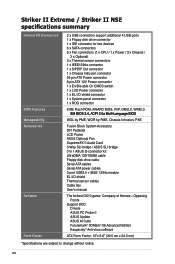
Striker II Extreme / Striker II NSE specifications summary Internal I/O Connectors BIOS Features Manageability Accessories Software Form Factor 2 x USB connectors support additional 4 USB ports 1 x Floppy disk drive connector 1 x IDE connector for two devices 6 x SATA connectors... 1394a module EL I/O shield Thermal sensor cables Cable ties User's manual The hottest DX10 game: Company of Heroes-Opposing Fronts Support DVD: Drivers ASUS PC Probe II ASUS Update ASUS AI Suite Futuremark® 3DMark® 06 Advanced Edition Kaspersky® Anti-virus software ATX Form Factor, 12"x 9.6" (30.5 cm x...
Striker II Extreme / Striker II NSE specifications summary Internal I/O Connectors BIOS Features Manageability Accessories Software Form Factor 2 x USB connectors support additional 4 USB ports 1 x Floppy disk drive connector 1 x IDE connector for two devices 6 x SATA connectors... 1394a module EL I/O shield Thermal sensor cables Cable ties User's manual The hottest DX10 game: Company of Heroes-Opposing Fronts Support DVD: Drivers ASUS PC Probe II ASUS Update ASUS AI Suite Futuremark® 3DMark® 06 Advanced Edition Kaspersky® Anti-virus software ATX Form Factor, 12"x 9.6" (30.5 cm x...
User Manual
Page 21
...no one knows when you to overclock the CPU speed in Windows® environment without the worries of booting the BIOS. Profile The motherboard features the ASUS O.C. C.P.R. (CPU Parameter Recall) When the system hangs due to overclocking failure, there is required before using C.P.R....ta��il�s�. ASUS O.C. Profile that no need to open the system chassis to conveniently store or load multiple BIOS settings. Frequency LED Worried that allows users to clear CMOS data. ROG Striker II Extreme / Striker II NSE 1-5 The onboard Frequency LED ...
...no one knows when you to overclock the CPU speed in Windows® environment without the worries of booting the BIOS. Profile The motherboard features the ASUS O.C. C.P.R. (CPU Parameter Recall) When the system hangs due to overclocking failure, there is required before using C.P.R....ta��il�s�. ASUS O.C. Profile that no need to open the system chassis to conveniently store or load multiple BIOS settings. Frequency LED Worried that allows users to clear CMOS data. ROG Striker II Extreme / Striker II NSE 1-5 The onboard Frequency LED ...

User Manual
Page 24
...42 for details. See pages 4-4 and 4-44 for details. ASUS Q-Connector The ASUS Q-Connector allows you to select the language of plugging in one complete module. ASUS CrashFree BIOS The ASUS CrashFree BIOS allows users to restore corrupted BIOS data using an OS-based flash utility. See page 4-20 ...Introduction See page 4-8 for details. This unique adapter eliminates the trouble of your choice from the available options. ASUS Multi-language BIOS The multi-language BIOS allows you to connect or disconnect chassis front panel cables in one easy step with one cable at a ...
...42 for details. See pages 4-4 and 4-44 for details. ASUS Q-Connector The ASUS Q-Connector allows you to select the language of plugging in one complete module. ASUS CrashFree BIOS The ASUS CrashFree BIOS allows users to restore corrupted BIOS data using an OS-based flash utility. See page 4-20 ...Introduction See page 4-8 for details. This unique adapter eliminates the trouble of your choice from the available options. ASUS Multi-language BIOS The multi-language BIOS allows you to connect or disconnect chassis front panel cables in one easy step with one cable at a ...

User Manual
Page 27
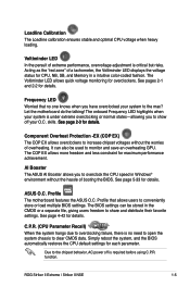
you can select the voltage to display in BIOS. There are also an LED for hard disk drive activity and an onboard switch for power status. Refer to the ...more information about voltage adjustment, refer to the motherboard, peripherals, and/or components. CPU_CRAZY CPU_HIGH CPU_NORMAL STRIKER II EXTREME STRIKER II EXTREME/ STRIKER II NSE CPU LED CPU Voltage CPU PLL Voltage Normal (green) 1.10000~1.50000 1.50000~1.60000 High (yellow) 1.50625~1.69375 1.62000~1.80000 Crazy (red) 1.70000~ 1.82000~ ROG Striker II Extreme / Striker II NSE 2-1 2.1 Before you proceed Take note ...
you can select the voltage to display in BIOS. There are also an LED for hard disk drive activity and an onboard switch for power status. Refer to the ...more information about voltage adjustment, refer to the motherboard, peripherals, and/or components. CPU_CRAZY CPU_HIGH CPU_NORMAL STRIKER II EXTREME STRIKER II EXTREME/ STRIKER II NSE CPU LED CPU Voltage CPU PLL Voltage Normal (green) 1.10000~1.50000 1.50000~1.60000 High (yellow) 1.50625~1.69375 1.62000~1.80000 Crazy (red) 1.70000~ 1.82000~ ROG Striker II Extreme / Striker II NSE 2-1 2.1 Before you proceed Take note ...
User Manual
Page 28
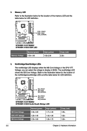
... Crazy (red) 1.95~ 1.62~ 1.80~ 2-2 Chapter 2: Hardware information Refer to display in BIOS. you can select the voltage to the illustration below for the location of the memory LED and the table below for LED definition. STRIKER II EXTREME DDR_CRAZY DDR_HIGH DDR_NORMAL STRIKER II EXTREME/ STRIKER II NSE DDR LED Memory Voltage Normal (green) 1.50~1.90 High (yellow) 1.92...
... Crazy (red) 1.95~ 1.62~ 1.80~ 2-2 Chapter 2: Hardware information Refer to display in BIOS. you can select the voltage to the illustration below for the location of the memory LED and the table below for LED definition. STRIKER II EXTREME DDR_CRAZY DDR_HIGH DDR_NORMAL STRIKER II EXTREME/ STRIKER II NSE DDR LED Memory Voltage Normal (green) 1.50~1.90 High (yellow) 1.92...

User Manual
Page 32
2.2.3 Motherboard layout CHA_FAN1 EL_CON LCD_CON KB_USB56 EATX12V 24.5cm (9.6in) SPDIF_O12 CLR_CMOS E1394 LGA775 CPU_FAN FREQUENCY CPU_CRAZY CPU_HIGH CPU_NORMAL BIOS EATXPWR DDR3 DIMM_A1 (64bit, 240-pin module) DDR3 DIMM_A2 (64bit, 240-pin ...STRIKER II EXTREME* PCI1 VIA VT6308P PCIEX16_2 NVIDIA® nForce® 570 SLI™ SB_CRAZY SB_HIGH SB_NORMAL SATA3 SATA4 SATA5 SATA6 Super I/O IE1394_2 OPT_TEMP3 PCI2 OPT_FAN3 USB78 USB910 CHASSIS ADH CLRTC_SW CHA_FAN3 RESET HD_LED PANEL • *The model name shows Striker II NSE if you purchase a Striker II NSE motherboard...
2.2.3 Motherboard layout CHA_FAN1 EL_CON LCD_CON KB_USB56 EATX12V 24.5cm (9.6in) SPDIF_O12 CLR_CMOS E1394 LGA775 CPU_FAN FREQUENCY CPU_CRAZY CPU_HIGH CPU_NORMAL BIOS EATXPWR DDR3 DIMM_A1 (64bit, 240-pin module) DDR3 DIMM_A2 (64bit, 240-pin ...STRIKER II EXTREME* PCI1 VIA VT6308P PCIEX16_2 NVIDIA® nForce® 570 SLI™ SB_CRAZY SB_HIGH SB_NORMAL SATA3 SATA4 SATA5 SATA6 Super I/O IE1394_2 OPT_TEMP3 PCI2 OPT_FAN3 USB78 USB910 CHASSIS ADH CLRTC_SW CHA_FAN3 RESET HD_LED PANEL • *The model name shows Striker II NSE if you purchase a Striker II NSE motherboard...

User Manual
Page 48
... slot and press firmly until the card is already installed in a chassis). 3. Turn on the next page. 3. Refer to the table on BIOS setup. 2. See Chapter 4 for information on the next page for later use . Before installing the expansion card, read the documentation that you ...removed earlier. 6. Remove the system unit cover (if your motherboard is completely seated on shared slots, ensure that the drivers support "Share IRQ" or that they support. Replace the system cover. 2.5.2 ...
... slot and press firmly until the card is already installed in a chassis). 3. Turn on the next page. 3. Refer to the table on BIOS setup. 2. See Chapter 4 for information on the next page for later use . Before installing the expansion card, read the documentation that you ...removed earlier. 6. Remove the system unit cover (if your motherboard is completely seated on shared slots, ensure that the drivers support "Share IRQ" or that they support. Replace the system cover. 2.5.2 ...
User Manual
Page 52
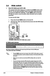
You can automatically reset CPU parameter settings to default values. STRIKER II EXTREME CLRTC_SW Enable (Default) Disable STRIKER II EXTREME/ STRIKER II NSE Clear RTC RAM slide switch clr CMOS switch behavior System power state G3* S5* S0 (DOS mode) S0 (OS mode) S1 S3 S4 Clearing ... the shutdwon function in S0 mode (DOS mode) still works. • Make sure to re-enter your previous BIOS settings after you easily to function, pressing down and reboot the system so the BIOS can clear the CMOS memory and system setup parameters by erasing the CMOS RTC RAM data. Clear RTC...
You can automatically reset CPU parameter settings to default values. STRIKER II EXTREME CLRTC_SW Enable (Default) Disable STRIKER II EXTREME/ STRIKER II NSE Clear RTC RAM slide switch clr CMOS switch behavior System power state G3* S5* S0 (DOS mode) S0 (OS mode) S1 S3 S4 Clearing ... the shutdwon function in S0 mode (DOS mode) still works. • Make sure to re-enter your previous BIOS settings after you easily to function, pressing down and reboot the system so the BIOS can clear the CMOS memory and system setup parameters by erasing the CMOS RTC RAM data. Clear RTC...
User Manual
Page 57
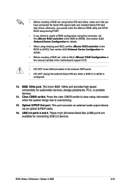
...Onboard Device Configuration for details. • Before creating a RAID set, refer to 5.4.4 JMicron® RAID Configuration or the manual bundled in the motherboard support DVD. • DO NOT insert different cables to the external SATA ports. • DO NOT unplug the external Serial ATA box when a... Onboard Device Configuration for details. • When using hot-plug and NCQ, set the JMicron RAID controller in the BIOS to [AHCI]. ROG Striker II Extreme / Striker II NSE 2-31 USB 2.0 ports 5 and 6. • Before creating a RAID set using this connector, set the JMicron RAID controller in ...
...Onboard Device Configuration for details. • Before creating a RAID set, refer to 5.4.4 JMicron® RAID Configuration or the manual bundled in the motherboard support DVD. • DO NOT insert different cables to the external SATA ports. • DO NOT unplug the external Serial ATA box when a... Onboard Device Configuration for details. • When using hot-plug and NCQ, set the JMicron RAID controller in the BIOS to [AHCI]. ROG Striker II Extreme / Striker II NSE 2-31 USB 2.0 ports 5 and 6. • Before creating a RAID set using this connector, set the JMicron RAID controller in ...

User Manual
Page 59
...right angle side ROG Striker II Extreme / Striker II NSE 2-33 Or you can connect Serial ATA boot/data hard disk drives to these connectors, enable the [RAID Enabled] item in the motherboard support DVD. STRIKER II EXTREME SATA5 GND RSATA_TXP5 RSATA_TXN5 ...STRIKER II EXTREME/ STRIKER II NSE SATA connector You must install the Windows® XP Service Pack 1 before using Windows® XP or later version. The Serial ATA RAID feature (RAID 0/RAID 1/RAID 5/RAID 10) is available only if you intend to 5.4.2 NVIDIA® RAID configurations or the manual bundled in the BIOS...
...right angle side ROG Striker II Extreme / Striker II NSE 2-33 Or you can connect Serial ATA boot/data hard disk drives to these connectors, enable the [RAID Enabled] item in the motherboard support DVD. STRIKER II EXTREME SATA5 GND RSATA_TXP5 RSATA_TXN5 ...STRIKER II EXTREME/ STRIKER II NSE SATA connector You must install the Windows® XP Service Pack 1 before using Windows® XP or later version. The Serial ATA RAID feature (RAID 0/RAID 1/RAID 5/RAID 10) is available only if you intend to 5.4.2 NVIDIA® RAID configurations or the manual bundled in the BIOS...

User Manual
Page 61
...motherboard! Thermal sensor cable connectors (2-pin OPT_TEMP1/2/3) These connectors are for details. 5. Connect the thermal sensor cables to page 4-35 for temperature monitoring. Connect the IEEE 1394a module cable to this connector, then install the module to the IEEE 1394a connector. Refer to these connectors. TPA2GND TPB2+12V GND STRIKER II EXTREME... OPT_TEMP1 Temperature Ground STRIKER II EXTREME OPT_TEMP2 Temperature Ground OPT_TEMP3 STRIKER II EXTREME/ STRIKER II NSE Thermal sensor cable connectors Enable OPT1/2/3 Cable Overheat Protection in BIOS if you connect ...
...motherboard! Thermal sensor cable connectors (2-pin OPT_TEMP1/2/3) These connectors are for details. 5. Connect the thermal sensor cables to page 4-35 for temperature monitoring. Connect the IEEE 1394a module cable to this connector, then install the module to the IEEE 1394a connector. Refer to these connectors. TPA2GND TPB2+12V GND STRIKER II EXTREME... OPT_TEMP1 Temperature Ground STRIKER II EXTREME OPT_TEMP2 Temperature Ground OPT_TEMP3 STRIKER II EXTREME/ STRIKER II NSE Thermal sensor cable connectors Enable OPT1/2/3 Cable Overheat Protection in BIOS if you connect ...

User Manual
Page 67
... you turn on the BIOS settings. The IDE LED lights up when you to the HDD. • System warning speaker (4-pin SPEAKER) This 4-pin connector is for the HDD Activity LED. ROG Striker II Extreme / Striker II NSE 2-41 PWR Ground Reset Ground PANEL PIN 1 STRIKER II EXTREME IDE_LED PWRSW RESET * Requires an ATX power supply STRIKER II EXTREME/ STRIKER II NSE System panel...
... you turn on the BIOS settings. The IDE LED lights up when you to the HDD. • System warning speaker (4-pin SPEAKER) This 4-pin connector is for the HDD Activity LED. ROG Striker II Extreme / Striker II NSE 2-41 PWR Ground Reset Ground PANEL PIN 1 STRIKER II EXTREME IDE_LED PWRSW RESET * Requires an ATX power supply STRIKER II EXTREME/ STRIKER II NSE System panel...

User Manual
Page 75
... see anything within 30 seconds from the time you press the ATX power button. At power on test. Connect the power cord to enter the BIOS Setup. Be sure that is equipped with "green" standards or if it has a "power standby" feature, the monitor LED may have failed... surge protector. 5. 3.1 Starting up . The system then runs the power-on the chain) c. Follow the instructions in the following order: a. ROG Striker II Extreme / Striker II NSE 3-1 After making all switches are off. 3. Connect the power cord to the power connector at the back of the system chassis. 4.
... see anything within 30 seconds from the time you press the ATX power button. At power on test. Connect the power cord to enter the BIOS Setup. Be sure that is equipped with "green" standards or if it has a "power standby" feature, the monitor LED may have failed... surge protector. 5. 3.1 Starting up . The system then runs the power-on the chain) c. Follow the instructions in the following order: a. ROG Striker II Extreme / Striker II NSE 3-1 After making all switches are off. 3. Connect the power cord to the power connector at the back of the system chassis. 4.


