SABERTOOTH 990FX R2.0 Layout - Asus
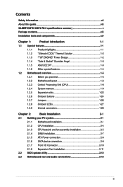
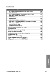
SABERTOOTH 990FX R2.0 Layout
View Results Below
Free Asus SABERTOOTH 990FX R2.0 manuals!
Problems with Asus SABERTOOTH 990FX R2.0?
Ask a Question
Free Asus SABERTOOTH 990FX R2.0 manuals!
Problems with Asus SABERTOOTH 990FX R2.0?
Ask a Question
Related Manual Pages


Similar Questions

I Need A Drawing Of The Asus Sabertooth 990fx R2.0 Motherboard Layout
(Posted by stephenmark1 4 years ago)

Need Layout For My Asus M2n68-am M/b. Need To Hook Up Usb, On/off Switch, Etc..
(Posted by chico329 11 years ago)