SABERTOOTH 990FX R2.0 User's Manual
Page 3
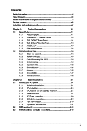
... this guide...viii SABERTOOTH 990FX R2.0 specifications summary x Package contents...xiii Installation tools and components xiv Chapter 1: Product introduction 1-1 1.1 Special features 1-1 1.1.1 Product highlights 1-1 1.1.2 "Ultimate COOL!" Thermal Solution 1-2 1.1.3 "TUF ENGINE!" Power Design 1-2 1.1.4 "Safe & Stable!" Guardian Angel 1-3 1.1.5 ASUS EZ DIY 1-3 1.1.6 Other special features 1-4 1.2 Motherboard overview 1-5 1.2.1 Before you proceed 1-5 1.2.2 Motherboard layout 1-6 1.2.3 Central Processing Unit (CPU 1-8 1.2.4 System memory 1-9 1.2.5 Expansion...
... this guide...viii SABERTOOTH 990FX R2.0 specifications summary x Package contents...xiii Installation tools and components xiv Chapter 1: Product introduction 1-1 1.1 Special features 1-1 1.1.1 Product highlights 1-1 1.1.2 "Ultimate COOL!" Thermal Solution 1-2 1.1.3 "TUF ENGINE!" Power Design 1-2 1.1.4 "Safe & Stable!" Guardian Angel 1-3 1.1.5 ASUS EZ DIY 1-3 1.1.6 Other special features 1-4 1.2 Motherboard overview 1-5 1.2.1 Before you proceed 1-5 1.2.2 Motherboard layout 1-6 1.2.3 Central Processing Unit (CPU 1-8 1.2.4 System memory 1-9 1.2.5 Expansion...

SABERTOOTH 990FX R2.0 User's Manual
Page 11
Guardian Angel - USB 3.0 Boost Network iControl ASUS UEFI BIOS EZ Mode USB BIOS Flashback AI Suite II ASUS Q-Connector ASUS Q-Shield ASUS Q-LED (CPU, DRAM, VGA, Boot Device LED) ASUS Q-Slot ASUS Q-DIMM ASUS O.C. TUF Thermal radar TUF ENGINE! Anti Surge Front panel USB 3.0 ... Switching Power (E.S.P.) design Safe & Stable! ASUS DIGI+ Power Control utility - Profile Ai Charger+ ASUS EZ Flash 2 ASUS MyLogo2 Multi-language BIOS (continued on the next page) xi TUF CeraM!X heatsink coating technology - SABERTOOTH 990FX R2.0 specifications summary USB Exclusive TUF features Other special...
Guardian Angel - USB 3.0 Boost Network iControl ASUS UEFI BIOS EZ Mode USB BIOS Flashback AI Suite II ASUS Q-Connector ASUS Q-Shield ASUS Q-LED (CPU, DRAM, VGA, Boot Device LED) ASUS Q-Slot ASUS Q-DIMM ASUS O.C. TUF Thermal radar TUF ENGINE! Anti Surge Front panel USB 3.0 ... Switching Power (E.S.P.) design Safe & Stable! ASUS DIGI+ Power Control utility - Profile Ai Charger+ ASUS EZ Flash 2 ASUS MyLogo2 Multi-language BIOS (continued on the next page) xi TUF CeraM!X heatsink coating technology - SABERTOOTH 990FX R2.0 specifications summary USB Exclusive TUF features Other special...
SABERTOOTH 990FX R2.0 User's Manual
Page 21
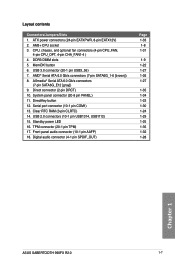
...32 1-28 Chapter 1 ASUS SABERTOOTH 990FX R2.0 1-7 USB 3.0 connector (20-1 pin USB3_56) 7. ASmedia® Serial ATA 6.0 Gb/s connectors (7-pin SATA6G_E12 [gray]) 9. Serial port connector (10-1 pin COM1) 13. AM3+ CPU socket 3. button 6. System panel connector (20-8 pin PANEL) 11. CPU, chassis, and optional ...fan connectors (4-pin CPU_FAN, 4-pin CPU_OPT, 4-pin CHA_FAN1-4 ) 4. USB 2.0 connectors (10-1 pin USB1314, USB1112) 15. Standby power LED 16. DDR3 DIMM slots ...
...32 1-28 Chapter 1 ASUS SABERTOOTH 990FX R2.0 1-7 USB 3.0 connector (20-1 pin USB3_56) 7. ASmedia® Serial ATA 6.0 Gb/s connectors (7-pin SATA6G_E12 [gray]) 9. Serial port connector (10-1 pin COM1) 13. AM3+ CPU socket 3. button 6. System panel connector (20-8 pin PANEL) 11. CPU, chassis, and optional ...fan connectors (4-pin CPU_FAN, 4-pin CPU_OPT, 4-pin CHA_FAN1-4 ) 4. USB 2.0 connectors (10-1 pin USB1314, USB1112) 15. Standby power LED 16. DDR3 DIMM slots ...
SABERTOOTH 990FX R2.0 User's Manual
Page 41
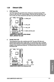
... problem is solved. 2. Chapter 1 ASUS SABERTOOTH 990FX R2.0 1-27 If an error is ON, in sleep mode, or in any motherboard component. POST State LEDs The POST State LEDs provide the status of the onboard LED. Standby Power LED The motherboard comes with a standby power LED. This is a reminder that the system...down the system and unplug the power cable before removing or plugging in soft‑off mode. 1.2.8 Onboard LEDs 1. The illustration below shows the location of these key components during POST (Power-On-Self Test): CPU, memory modules, VGA card, and hard disk drives.
... problem is solved. 2. Chapter 1 ASUS SABERTOOTH 990FX R2.0 1-27 If an error is ON, in sleep mode, or in any motherboard component. POST State LEDs The POST State LEDs provide the status of the onboard LED. Standby Power LED The motherboard comes with a standby power LED. This is a reminder that the system...down the system and unplug the power cable before removing or plugging in soft‑off mode. 1.2.8 Onboard LEDs 1. The illustration below shows the location of these key components during POST (Power-On-Self Test): CPU, memory modules, VGA card, and hard disk drives.


