User Manual
Page 4
... panel 2-39 2.9 Onboard LEDs 2-40 2.10 Starting up for the first time 2-41 2.11 Turning off the computer 2-41 Chapter 3: BIOS setup 3.1 Knowing BIOS 3-1 3.2 Updating BIOS 3-1 3.2.1 ASUS Update utility 3-2 3.2.2 ASUS EZ Flash 2 utility 3-4 3.2.3 ASUS CrashFree BIOS 3 utility 3-5 3.2.4 ASUS BIOS Updater 3-5 3.3 BIOS setup program 3-8 3.3.1 BIOS menu screen 3-8 3.3.2 Menu bar 3-8 3.3.3 Navigation keys 3-9 3.3.4 Menu items 3-9 3.3.5 Submenu items 3-9 3.3.6 Configuration...
... panel 2-39 2.9 Onboard LEDs 2-40 2.10 Starting up for the first time 2-41 2.11 Turning off the computer 2-41 Chapter 3: BIOS setup 3.1 Knowing BIOS 3-1 3.2 Updating BIOS 3-1 3.2.1 ASUS Update utility 3-2 3.2.2 ASUS EZ Flash 2 utility 3-4 3.2.3 ASUS CrashFree BIOS 3 utility 3-5 3.2.4 ASUS BIOS Updater 3-5 3.3 BIOS setup program 3-8 3.3.1 BIOS menu screen 3-8 3.3.2 Menu bar 3-8 3.3.3 Navigation keys 3-9 3.3.4 Menu items 3-9 3.3.5 Submenu items 3-9 3.3.6 Configuration...
User Manual
Page 12
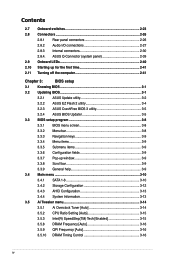
SABERTOOTH 55i specifications summary ASUS TUF features Other special features Back panel I/O ports Internal I /O ports 3 x USB connectors support additional 6 USB ports 1 x IDE connector 6 x SATA connectors 2 x Drive Xpert SATA connectors (orange and white) 1 x CPU Fan connector 2 x Chassis Fan connectors (1 x 4-pin, 1 ... Switching Power Design for 3VSB/1.8V/1.05V - EMI Eliminator ASUS Q-Connector ASUS Q-Shield ASUS Q-LED (CPU, DRAM, VGA, Boot Device LED) ASUS Q-Slot ASUS Q-DIMM ASUS CrashFree BIOS 3 ASUS EZ Flash 2 ASUS MyLogo 2™ ASUS O.C. button 1 x Power on switch 1 x Reset ...
SABERTOOTH 55i specifications summary ASUS TUF features Other special features Back panel I/O ports Internal I /O ports 3 x USB connectors support additional 6 USB ports 1 x IDE connector 6 x SATA connectors 2 x Drive Xpert SATA connectors (orange and white) 1 x CPU Fan connector 2 x Chassis Fan connectors (1 x 4-pin, 1 ... Switching Power Design for 3VSB/1.8V/1.05V - EMI Eliminator ASUS Q-Connector ASUS Q-Shield ASUS Q-LED (CPU, DRAM, VGA, Boot Device LED) ASUS Q-Slot ASUS Q-DIMM ASUS CrashFree BIOS 3 ASUS EZ Flash 2 ASUS MyLogo 2™ ASUS O.C. button 1 x Power on switch 1 x Reset ...

User Manual
Page 60
You may disable the POST State LEDs in sequence during motherboard booting process. 2.9 Onboard LEDs POST State LEDs POST State LEDs check key components (CPU, DRAM, VGA card, and HDD) in BIOS. Refer to the error device will continue lighting until the problem is solved. Chapter 2 2-40 Chapter 2: Hardware information If an error is found , the LED next to section 3.8.2 Boot Settings Configuration for details. This user-friendly design provides an intuitional way to locate the root problem within a second.
You may disable the POST State LEDs in sequence during motherboard booting process. 2.9 Onboard LEDs POST State LEDs POST State LEDs check key components (CPU, DRAM, VGA card, and HDD) in BIOS. Refer to the error device will continue lighting until the problem is solved. Chapter 2 2-40 Chapter 2: Hardware information If an error is found , the LED next to section 3.8.2 Boot Settings Configuration for details. This user-friendly design provides an intuitional way to locate the root problem within a second.


