
User Manual
Page 5
... Spread Spectrum [Auto 3-20 3.5.22 PCIE Spread Spectrum [Auto 3-20 3.6 Advanced menu 3-21 3.6.1 CPU Configuration 3-21 3.6.2 North Bridge Configuration 3-23 3.6.3 Onboard Devices Configuration 3-24 3.6.4 USB Configuration 3-25 3.6.5 PCIPnP 3-26 3.6.6 Intel VT-d [Disabled 3-26 3.6.7 T.Probe [Enabled 3-26 3.7 Power menu 3-27 3.7.1 Suspend Mode [Auto 3-27 3.7.2 Repost Video on S3 ... APM Configuration 3-28 3.7.7 Hardware Monitor 3-29 3.8 Boot menu 3-30 3.8.1 Boot Device Priority 3-30 3.8.2 Boot Settings Configuration 3-31 3.8.3 Security 3-32 3.9 Tools menu 3-34 3.9.1 ASUS O.C.
... Spread Spectrum [Auto 3-20 3.5.22 PCIE Spread Spectrum [Auto 3-20 3.6 Advanced menu 3-21 3.6.1 CPU Configuration 3-21 3.6.2 North Bridge Configuration 3-23 3.6.3 Onboard Devices Configuration 3-24 3.6.4 USB Configuration 3-25 3.6.5 PCIPnP 3-26 3.6.6 Intel VT-d [Disabled 3-26 3.6.7 T.Probe [Enabled 3-26 3.7 Power menu 3-27 3.7.1 Suspend Mode [Auto 3-27 3.7.2 Repost Video on S3 ... APM Configuration 3-28 3.7.7 Hardware Monitor 3-29 3.8 Boot menu 3-30 3.8.1 Boot Device Priority 3-30 3.8.2 Boot Settings Configuration 3-31 3.8.3 Security 3-32 3.9 Tools menu 3-34 3.9.1 ASUS O.C.
User Manual
Page 6
...the support DVD 4-1 4.2.2 Obtaining the software manuals 4-2 4.3 Software information 4-3 4.3.1 ASUS PC Probe II 4-3 4.3.2 ASUS Fan Xpert 4-4 4.3.3 VIA® High Definition Audio utility 4-5 4.3.4 ASUS Drive Xpert 4-6 4.3.5 ASUS T.Probe 4-7 4.4 RAID configurations 4-8 4.4.1 RAID definitions 4-8 4.4.2 Installing Serial ATA ...disk in Windows 4-13 4.5.3 Installing the RAID driver during Windows® OS installation....... 4-14 4.5.4 Using a USB floppy disk drive 4-14 Chapter 5: Multiple GPU technology support 5.1 ATI® CrossFireX™ technology 5-1 5.1.1 ...
...the support DVD 4-1 4.2.2 Obtaining the software manuals 4-2 4.3 Software information 4-3 4.3.1 ASUS PC Probe II 4-3 4.3.2 ASUS Fan Xpert 4-4 4.3.3 VIA® High Definition Audio utility 4-5 4.3.4 ASUS Drive Xpert 4-6 4.3.5 ASUS T.Probe 4-7 4.4 RAID configurations 4-8 4.4.1 RAID definitions 4-8 4.4.2 Installing Serial ATA ...disk in Windows 4-13 4.5.3 Installing the RAID driver during Windows® OS installation....... 4-14 4.5.4 Using a USB floppy disk drive 4-14 Chapter 5: Multiple GPU technology support 5.1 ATI® CrossFireX™ technology 5-1 5.1.1 ...
User Manual
Page 11
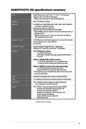
...Storage Technology supports SATA RAID 0, 1, 5, and 10 JMicron® JMB363 SATA & PATA controller - 1 x Ultra DMA 133/100/66 for up to www.asus.com or this user manual for Intel CPU support list Intel® P55 Express Chipset 4 x DIMM, max. 16GB, DDR3 2000 / 1800 / 1600 / ...Detection, Multi-streaming, and Front Panel Jack-Retasking - Absolute Pitch BD192/24 featuring ENVY HD - SABERTOOTH 55i specifications summary CPU Chipset Memory Expansion slots Multi-GPU support Storage LAN USB IEEE 1394 Audio LGA1156 socket for Intel® Core™ i7 / Core™ i5 Processors Supports...
...Storage Technology supports SATA RAID 0, 1, 5, and 10 JMicron® JMB363 SATA & PATA controller - 1 x Ultra DMA 133/100/66 for up to www.asus.com or this user manual for Intel CPU support list Intel® P55 Express Chipset 4 x DIMM, max. 16GB, DDR3 2000 / 1800 / 1600 / ...Detection, Multi-streaming, and Front Panel Jack-Retasking - Absolute Pitch BD192/24 featuring ENVY HD - SABERTOOTH 55i specifications summary CPU Chipset Memory Expansion slots Multi-GPU support Storage LAN USB IEEE 1394 Audio LGA1156 socket for Intel® Core™ i7 / Core™ i5 Processors Supports...
User Manual
Page 12
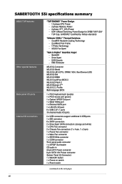
... - Thermal Solutions - MemOK! - SABERTOOTH 55i specifications summary ASUS TUF features Other special features Back panel I/O ports Internal I /O ports 3 x USB connectors support additional 6 USB ports 1 x IDE connector 6 x... SATA connectors 2 x Drive Xpert SATA connectors (orange and white) 1 x CPU Fan connector 2 x Chassis Fan connectors (1 x 4-pin, 1 x 3-pin) 1 x Power Fan connector 1 x Mem Fan connector 1 x IEEE1394a connector 1 x COM connector Front panel audio connector 1 x S/PDIF Out header CD audio in 24-pin ATX...
... - Thermal Solutions - MemOK! - SABERTOOTH 55i specifications summary ASUS TUF features Other special features Back panel I/O ports Internal I /O ports 3 x USB connectors support additional 6 USB ports 1 x IDE connector 6 x... SATA connectors 2 x Drive Xpert SATA connectors (orange and white) 1 x CPU Fan connector 2 x Chassis Fan connectors (1 x 4-pin, 1 x 3-pin) 1 x Power Fan connector 1 x Mem Fan connector 1 x IEEE1394a connector 1 x COM connector Front panel audio connector 1 x S/PDIF Out header CD audio in 24-pin ATX...
User Manual
Page 15
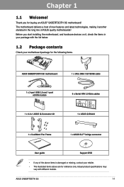
... or missing, contact your motherboard package for buying an ASUS® SABERTOOTH 55i motherboard! Thank you start installing the motherboard, and hardware devices on it another standout in the long line of the above are for reference only. Before you for the following items. Chapter 1 ASUS SABERTOOTH 55i motherboard 1 x Ultra DMA 133/100/66 cable 1 x 2-port USB 2.0 and 1-port eSATA module...
... or missing, contact your motherboard package for buying an ASUS® SABERTOOTH 55i motherboard! Thank you start installing the motherboard, and hardware devices on it another standout in the long line of the above are for reference only. Before you for the following items. Chapter 1 ASUS SABERTOOTH 55i motherboard 1 x Ultra DMA 133/100/66 cable 1 x 2-port USB 2.0 and 1-port eSATA module...
User Manual
Page 23
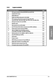
... CHA_FAN1, 3-pin CHA_FAN2, 3-pin PWR_FAN, 3-pin MEM_FAN) 6. Serial port connector (10-1 pin COM1) 7. switch 8. USB connectors (10-1 pin USB910, USB1112, USB1314) 13. Reset switch 15. Digital audio connector (4-1 pin SPDIF_OUT) 18. LGA1156... 2-34 2-24 2-30 2-31 2-38 2-32 2-33 2-22 2-23 2-23 2-34 2-36 2-33 2-36 Chapter 2 ASUS SABERTOOTH 55i 2-3 IDE connector (40-1 pin PRI_EIDE) 9. Power-on switch 16. Intel® P55 Serial ATA 3.0 Gb/s connectors (7-pin... 19. DRAM overvoltage setting switch (OV_DRAM) 5. ATX power connectors (24-pin EATXPWR, 8-pin EATX12V) 2.
... CHA_FAN1, 3-pin CHA_FAN2, 3-pin PWR_FAN, 3-pin MEM_FAN) 6. Serial port connector (10-1 pin COM1) 7. switch 8. USB connectors (10-1 pin USB910, USB1112, USB1314) 13. Reset switch 15. Digital audio connector (4-1 pin SPDIF_OUT) 18. LGA1156... 2-34 2-24 2-30 2-31 2-38 2-32 2-33 2-22 2-23 2-23 2-34 2-36 2-33 2-36 Chapter 2 ASUS SABERTOOTH 55i 2-3 IDE connector (40-1 pin PRI_EIDE) 9. Power-on switch 16. Intel® P55 Serial ATA 3.0 Gb/s connectors (7-pin... 19. DRAM overvoltage setting switch (OV_DRAM) 5. ATX power connectors (24-pin EATXPWR, 8-pin EATX12V) 2.

User Manual
Page 39
... 2 - JMicron ATA Controller - - SATA controller 2 - - - - - shared - - LAN1 (8112) - - - USB 2.0 controller 1 - - - - - - - PCI_1 shared PCI_2 - PCIE x1_1 shared - - - - - - - HD Audio - - - - - - ASUS SABERTOOTH 55i 2-19 PCIE x16_2 shared - - - - - - - shared - - - - - shared - - - - - -... this motherboard A B C D E F G H PCIE x16_1 shared - - - - - - - shared - - - - SATA controller 1 - - - - - shared USB 2.0 controller 2 shared - - - - - - - 1394 controller - - shared -...
... 2 - JMicron ATA Controller - - SATA controller 2 - - - - - shared - - LAN1 (8112) - - - USB 2.0 controller 1 - - - - - - - PCI_1 shared PCI_2 - PCIE x1_1 shared - - - - - - - HD Audio - - - - - - ASUS SABERTOOTH 55i 2-19 PCIE x16_2 shared - - - - - - - shared - - - - - shared - - - - - -... this motherboard A B C D E F G H PCIE x16_1 shared - - - - - - - shared - - - - SATA controller 1 - - - - - shared USB 2.0 controller 2 shared - - - - - - - 1394 controller - - shared -...

User Manual
Page 40
...specifications. Refer to the figure below for the location of the slots. 2.5.4 PCI slots The PCI slots support cards such as a LAN card, SCSI card, USB card, and other cards that comply with PCI specifications. Chapter 2 PCI slot 2 PCI slot 1 PCIe 2.0 x16_2 slot (black, at x8 link) PCI Express... x1_1 slot 2-20 Chapter 2: Hardware information Refer to the figure below for the location of the slots. 2.5.5 PCI Express 2.0 x1 slots (2.5GT/s) This motherboard supports PCI Express x1 network cards, SCSI cards and other cards that comply with the PCI Express specifications.
...specifications. Refer to the figure below for the location of the slots. 2.5.4 PCI slots The PCI slots support cards such as a LAN card, SCSI card, USB card, and other cards that comply with PCI specifications. Chapter 2 PCI slot 2 PCI slot 1 PCIe 2.0 x16_2 slot (black, at x8 link) PCI Express... x1_1 slot 2-20 Chapter 2: Hardware information Refer to the figure below for the location of the slots. 2.5.5 PCI Express 2.0 x1 slots (2.5GT/s) This motherboard supports PCI Express x1 network cards, SCSI cards and other cards that comply with the PCI Express specifications.
User Manual
Page 46
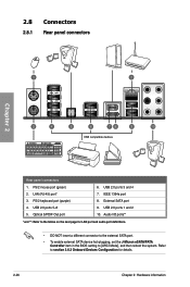
External SATA port 9. USB 2.0 ports 1 and 2 10. USB 2.0 ports 3 and 4 7. Refer to [AHCI Mode], and then reboot the system. LAN (RJ-45) port* 3. PS/2 keyboard port (purple) 4. Optical S/PDIF Out port 6. IEEE 1394a ... BIOS setting to section 3.6.3 Onboard Devices Configuration for details. 2-26 Chapter 2: Hardware information 2.8 Connectors 2.8.1 Rear panel connectors Chapter 2 Rear panel connectors 1. PS/2 mouse port (green) 2. USB 2.0 ports 5-8 5.
External SATA port 9. USB 2.0 ports 1 and 2 10. USB 2.0 ports 3 and 4 7. Refer to [AHCI Mode], and then reboot the system. LAN (RJ-45) port* 3. PS/2 keyboard port (purple) 4. Optical S/PDIF Out port 6. IEEE 1394a ... BIOS setting to section 3.6.3 Onboard Devices Configuration for details. 2-26 Chapter 2: Hardware information 2.8 Connectors 2.8.1 Rear panel connectors Chapter 2 Rear panel connectors 1. PS/2 mouse port (green) 2. USB 2.0 ports 5-8 5.
User Manual
Page 53
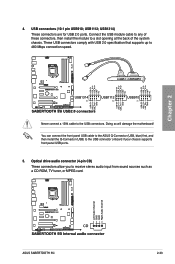
... supports front panel USB ports. 5. You can connect the front panel USB cable to the ASUS Q-Connector (USB, blue) first, and then install the Q-Connector (USB) to a slot opening at the back of the system chassis. USB connectors (10-1 pin USB910; USB1112; These USB connectors comply with USB 2.0 specification that ... drive audio connector (4-pin CD) These connectors allow you to 480 Mbps connection speed. USB1314) These connectors are for USB 2.0 ports. Never connect a 1394 cable to the USB connectors. Chapter 2 4. ASUS SABERTOOTH 55i 2-33 Doing so will damage the motherboard!
... supports front panel USB ports. 5. You can connect the front panel USB cable to the ASUS Q-Connector (USB, blue) first, and then install the Q-Connector (USB) to a slot opening at the back of the system chassis. USB connectors (10-1 pin USB910; USB1112; These USB connectors comply with USB 2.0 specification that ... drive audio connector (4-pin CD) These connectors allow you to 480 Mbps connection speed. USB1314) These connectors are for USB 2.0 ports. Never connect a 1394 cable to the USB connectors. Chapter 2 4. ASUS SABERTOOTH 55i 2-33 Doing so will damage the motherboard!

User Manual
Page 54
6. Serial port connector (10-1 pin COM1) This connector is purchased separately. 2-34 Chapter 2: Hardware information Never connect a USB cable to a slot opening at the back of the system chassis. Doing so will damage the motherboard! Chapter 2 The COM module is for an IEEE 1394a port. Connect the serial port module cable to this...
6. Serial port connector (10-1 pin COM1) This connector is purchased separately. 2-34 Chapter 2: Hardware information Never connect a USB cable to a slot opening at the back of the system chassis. Doing so will damage the motherboard! Chapter 2 The COM module is for an IEEE 1394a port. Connect the serial port module cable to this...
User Manual
Page 63
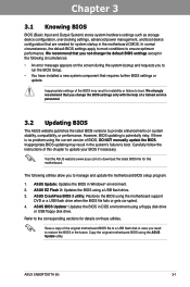
...the latest BIOS file for this chapter to manage and update the motherboard BIOS setup program. 1. ASUS CrashFree BIOS 3 utility: Restores the BIOS using the ASUS Update utility. Refer to ensure optimum performance. Chapter 3 ASUS SABERTOOTH 55i 3-1 In normal circumstances, the default BIOS settings apply to most ...8226; You have installed a new system component that requires further BIOS settings or update. Save a copy of the original motherboard BIOS file to a USB flash disk in the future. However, BIOS updating is no problem using the current version of BIOS, DO NOT manually ...
...the latest BIOS file for this chapter to manage and update the motherboard BIOS setup program. 1. ASUS CrashFree BIOS 3 utility: Restores the BIOS using the ASUS Update utility. Refer to ensure optimum performance. Chapter 3 ASUS SABERTOOTH 55i 3-1 In normal circumstances, the default BIOS settings apply to most ...8226; You have installed a new system component that requires further BIOS settings or update. Save a copy of the original motherboard BIOS file to a USB flash disk in the future. However, BIOS updating is no problem using the current version of BIOS, DO NOT manually ...
User Manual
Page 66
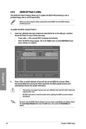
... the following. • Enter the BIOS setup program. 3.2.2 ASUS EZ Flash 2 utility The ASUS EZ Flash 2 feature allows you start using EZ Flash 2: 1. Chapter 3 3-4 Chapter 3: BIOS setup Insert the USB flash disk that contains the latest BIOS file to the USB port, and then launch EZ Flash 2 in any of these... two ways: • Press + during POST to prevent system boot failure! ASUSTek EZ Flash 2 BIOS ROM Utility V4.00b FLASH TYPE: MXIC 25L1605A Current ROM BOARD: SABERTOOTH 55i VER: 0301 DATE: 07/30/...
... the following. • Enter the BIOS setup program. 3.2.2 ASUS EZ Flash 2 utility The ASUS EZ Flash 2 feature allows you start using EZ Flash 2: 1. Chapter 3 3-4 Chapter 3: BIOS setup Insert the USB flash disk that contains the latest BIOS file to the USB port, and then launch EZ Flash 2 in any of these... two ways: • Press + during POST to prevent system boot failure! ASUSTek EZ Flash 2 BIOS ROM Utility V4.00b FLASH TYPE: MXIC 25L1605A Current ROM BOARD: SABERTOOTH 55i VER: 0301 DATE: 07/30/...
User Manual
Page 67
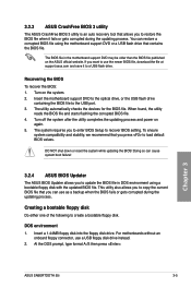
... floppy disk drive. Chapter 3 ASUS SABERTOOTH 55i 3-5 If you to enter BIOS Setup to recover BIOS setting. Turn on again. 5. The utility automatically checks the devices for the BIOS file. Creating a bootable floppy disk Do either one of the following to the USB port. 3. The system requires...power on the system. 2. The BIOS file in DOS environment using the motherboard support DVD or a USB flash drive that contains the BIOS file. Insert the motherboard support DVD to the optical drive, or the USB flash drive containing the BIOS file to create a bootable floppy disk. When...
... floppy disk drive. Chapter 3 ASUS SABERTOOTH 55i 3-5 If you to enter BIOS Setup to recover BIOS setting. Turn on again. 5. The utility automatically checks the devices for the BIOS file. Creating a bootable floppy disk Do either one of the following to the USB port. 3. The system requires...power on the system. 2. The BIOS file in DOS environment using the motherboard support DVD or a USB flash drive that contains the BIOS file. Insert the motherboard support DVD to the optical drive, or the USB flash drive containing the BIOS file to create a bootable floppy disk. When...
User Manual
Page 68
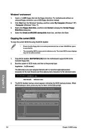
.... 1. The BIOS Updater backup screen appears indicating the BIOS backup process. For motherboards without an onboard floppy connector, use a USB floppy disk drive instead. 2. When BIOS backup is done! Click Start from the motherboard support DVD to continue. Insert a 1.44MB floppy disk into the floppy disk ... the file. • The succeeding BIOS screens are for DOS V1.00b [09/06/22] FLASH TYPE: MXIC 25L1605A Current ROM BOARD: SABERTOOTH 55i VER: 0301 DATE: 07/30/2009 Update ROM BOARD: Unknown VER: Unknown DATE: Unknown PATH: A:\ BIOS backup is done, press any ...
.... 1. The BIOS Updater backup screen appears indicating the BIOS backup process. For motherboards without an onboard floppy connector, use a USB floppy disk drive instead. 2. When BIOS backup is done! Click Start from the motherboard support DVD to continue. Insert a 1.44MB floppy disk into the floppy disk ... the file. • The succeeding BIOS screens are for DOS V1.00b [09/06/22] FLASH TYPE: MXIC 25L1605A Current ROM BOARD: SABERTOOTH 55i VER: 0301 DATE: 07/30/2009 Update ROM BOARD: Unknown VER: Unknown DATE: Unknown PATH: A:\ BIOS backup is done, press any ...
User Manual
Page 83
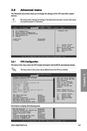
... to Sub Screen F1 General Help F10 Save and Exit ESC Exit v02.61 (C)Copyright 1985-2009, American Megatrends, Inc. ASUS SABERTOOTH 55i 3-21 Be cautious when changing the settings of the Advanced menu items. Incorrect field values can cause the system to display ... Advanced menu items allow you installed. Main Ai Tweaker BIOS SETUP UTILITY Advanced Power Boot CPU Configuration North Bridge Configuration Onboard Devices Configuration USB Configuration PCIPnP Intel VT-d T.Probe [Disabled] [Enabled] Tools Exit Configure CPU. ←→ Select Screen ↑↓ Select...
... to Sub Screen F1 General Help F10 Save and Exit ESC Exit v02.61 (C)Copyright 1985-2009, American Megatrends, Inc. ASUS SABERTOOTH 55i 3-21 Be cautious when changing the settings of the Advanced menu items. Incorrect field values can cause the system to display ... Advanced menu items allow you installed. Main Ai Tweaker BIOS SETUP UTILITY Advanced Power Boot CPU Configuration North Bridge Configuration Onboard Devices Configuration USB Configuration PCIPnP Intel VT-d T.Probe [Disabled] [Enabled] Tools Exit Configure CPU. ←→ Select Screen ↑↓ Select...

User Manual
Page 87
...] Disables the function. Configuration options: [Disabled] [3F8/IRQ4] [2F8/IRQ3] [3E8/IRQ4] [2E8/IRQ3] 3.6.4 USB Configuration The items in this menu allow you to detect the presence of USB devices at startup. Chapter 3 ASUS SABERTOOTH 55i 3-25 If detected, the USB controller legacy mode is disabled. [Enabled] Enables the support for operating systems without an EHCI...
...] Disables the function. Configuration options: [Disabled] [3F8/IRQ4] [2F8/IRQ3] [3E8/IRQ4] [2E8/IRQ3] 3.6.4 USB Configuration The items in this menu allow you to detect the presence of USB devices at startup. Chapter 3 ASUS SABERTOOTH 55i 3-25 If detected, the USB controller legacy mode is disabled. [Enabled] Enables the support for operating systems without an EHCI...

User Manual
Page 97
...A:\ A: Note [Enter] Select or Load [Up/Down/Home/End] Move [Tab] Switch [B] Backup [V] Drive Info [Esc] Exit • This function can be loaded. Chapter 3 ASUS SABERTOOTH 55i 3-35 Press to load the previous BIOS settings saved in the BIOS Flash. Profile Allows you update the BIOS file only coming from the same... memory/CPU configuration and BIOS version. • Only the CMO file can support devices such as a USB flash disk with FAT 32/16 format and single partition only. • DO NOT shut down or reset the system while updating the BIOS ...
...A:\ A: Note [Enter] Select or Load [Up/Down/Home/End] Move [Tab] Switch [B] Backup [V] Drive Info [Esc] Exit • This function can be loaded. Chapter 3 ASUS SABERTOOTH 55i 3-35 Press to load the previous BIOS settings saved in the BIOS Flash. Profile Allows you update the BIOS file only coming from the same... memory/CPU configuration and BIOS version. • Only the CMO file can support devices such as a USB flash disk with FAT 32/16 format and single partition only. • DO NOT shut down or reset the system while updating the BIOS ...
User Manual
Page 113
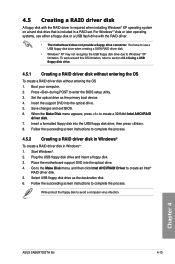
...create a 32/64bit Intel AHCI/RAID driver disk. 7. Set the optical drive as the destination disk. 6. Place the motherboard support DVD into the USB floppy disk drive, then press . 8. To work around this OS limitation, refer to avoid a computer virus infection. ...Write-protect the floppy disk to section 4.5.4 Using a USB floppy disk drive. 4.5.1 Creating a RAID driver disk without entering the OS To create a RAID driver disk without entering the OS 1. Boot your computer. 2. Chapter 4 ASUS SABERTOOTH 55i 4-13 Insert the support DVD into the optical drive. 5....
...create a 32/64bit Intel AHCI/RAID driver disk. 7. Set the optical drive as the destination disk. 6. Place the motherboard support DVD into the USB floppy disk drive, then press . 8. To work around this OS limitation, refer to avoid a computer virus infection. ...Write-protect the floppy disk to section 4.5.4 Using a USB floppy disk drive. 4.5.1 Creating a RAID driver disk without entering the OS To create a RAID driver disk without entering the OS 1. Boot your computer. 2. Chapter 4 ASUS SABERTOOTH 55i 4-13 Insert the support DVD into the optical drive. 5....
User Manual
Page 114
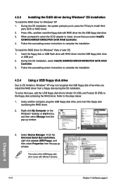
.... Select Device Manager. During the OS installation, select Intel(R) ICH8R/ICH9R/ICH10R/DO/PCH SATA RAID Controller. 3. Using another computer, plug the USB floppy disk drive, and insert the floppy disk containing the RAID driver. 2. 4.5.3 Installing the RAID driver during the OS installation. When prompted to... My Computer on the Windows® desktop or start menu, and then select Manage from the pop-up window. The name of the USB floppy disk drive varies with different vendors. During the OS installation, the system prompts you select Intel(R) ICH8R/ICH9R/ICH10R/DO/PCH SATA...
.... Select Device Manager. During the OS installation, select Intel(R) ICH8R/ICH9R/ICH10R/DO/PCH SATA RAID Controller. 3. Using another computer, plug the USB floppy disk drive, and insert the floppy disk containing the RAID driver. 2. 4.5.3 Installing the RAID driver during the OS installation. When prompted to... My Computer on the Windows® desktop or start menu, and then select Manage from the pop-up window. The name of the USB floppy disk drive varies with different vendors. During the OS installation, the system prompts you select Intel(R) ICH8R/ICH9R/ICH10R/DO/PCH SATA...


