User Manual
Page 4
... 2-39 2.9 Onboard LEDs 2-40 2.10 Starting up for the first time 2-41 2.11 Turning off the computer 2-41 Chapter 3: BIOS setup 3.1 Knowing BIOS 3-1 3.2 Updating BIOS 3-1 3.2.1 ASUS Update utility 3-2 3.2.2 ASUS EZ Flash 2 utility 3-4 3.2.3 ASUS CrashFree BIOS 3 utility 3-5 3.2.4 ASUS BIOS Updater 3-5 3.3 BIOS setup program 3-8 3.3.1 BIOS menu screen 3-8 3.3.2 Menu bar 3-8 3.3.3 Navigation keys 3-9 3.3.4 Menu items 3-9 3.3.5 Submenu items 3-9 3.3.6 Configuration fields 3-9 3.3.7 Pop-up window 3-9 3.3.8 Scroll bar 3-9 3.3.9 General...
... 2-39 2.9 Onboard LEDs 2-40 2.10 Starting up for the first time 2-41 2.11 Turning off the computer 2-41 Chapter 3: BIOS setup 3.1 Knowing BIOS 3-1 3.2 Updating BIOS 3-1 3.2.1 ASUS Update utility 3-2 3.2.2 ASUS EZ Flash 2 utility 3-4 3.2.3 ASUS CrashFree BIOS 3 utility 3-5 3.2.4 ASUS BIOS Updater 3-5 3.3 BIOS setup program 3-8 3.3.1 BIOS menu screen 3-8 3.3.2 Menu bar 3-8 3.3.3 Navigation keys 3-9 3.3.4 Menu items 3-9 3.3.5 Submenu items 3-9 3.3.6 Configuration fields 3-9 3.3.7 Pop-up window 3-9 3.3.8 Scroll bar 3-9 3.3.9 General...
User Manual
Page 6
... information 4-1 4.2.1 Running the support DVD 4-1 4.2.2 Obtaining the software manuals 4-2 4.3 Software information 4-3 4.3.1 ASUS PC Probe II 4-3 4.3.2 ASUS Fan Xpert 4-4 4.3.3 VIA® High Definition Audio utility 4-5 4.3.4 ASUS Drive Xpert 4-6 4.3.5 ASUS T.Probe 4-7 4.4 RAID configurations 4-8 4.4.1 RAID definitions 4-8 4.4.2 Installing Serial ATA hard disks 4-9 4.4.3 Setting the RAID item in BIOS 4-9 4.4.4 Intel® Matrix Storage Manager option ROM utility 4-9 4.5 Creating a RAID driver...
... information 4-1 4.2.1 Running the support DVD 4-1 4.2.2 Obtaining the software manuals 4-2 4.3 Software information 4-3 4.3.1 ASUS PC Probe II 4-3 4.3.2 ASUS Fan Xpert 4-4 4.3.3 VIA® High Definition Audio utility 4-5 4.3.4 ASUS Drive Xpert 4-6 4.3.5 ASUS T.Probe 4-7 4.4 RAID configurations 4-8 4.4.1 RAID definitions 4-8 4.4.2 Installing Serial ATA hard disks 4-9 4.4.3 Setting the RAID item in BIOS 4-9 4.4.4 Intel® Matrix Storage Manager option ROM utility 4-9 4.5 Creating a RAID driver...
User Manual
Page 9
... by your dealer. Where to find more information Refer to the ASUS contact information. 2. Refer to the following parts: • Chapter 1: Product introduction This chapter describes the features of the motherboard and the new technology it supports. • Chapter 2: Hardware... 5: Multiple GPU technology support This chapter describes how to change system settings through the BIOS Setup menus. ASUS websites The ASUS website provides updated information on the motherboard. • Chapter 3: BIOS setup This chapter tells how to install and configure multiple ATI® CrossFireX™ ...
... by your dealer. Where to find more information Refer to the ASUS contact information. 2. Refer to the following parts: • Chapter 1: Product introduction This chapter describes the features of the motherboard and the new technology it supports. • Chapter 2: Hardware... 5: Multiple GPU technology support This chapter describes how to change system settings through the BIOS Setup menus. ASUS websites The ASUS website provides updated information on the motherboard. • Chapter 3: BIOS setup This chapter tells how to install and configure multiple ATI® CrossFireX™ ...
User Manual
Page 12
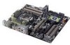
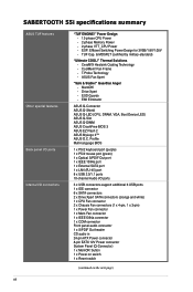
SABERTOOTH 55i specifications summary ASUS TUF features Other special features Back panel I/O ports Internal I /O ports 3 x USB connectors support additional 6 USB ports 1 x IDE connector 6 x SATA connectors 2 x Drive Xpert SATA ... 1 x COM connector Front panel audio connector 1 x S/PDIF Out header CD audio in 24-pin ATX Power connector 8-pin EATX 12V Power connector System Panel (Q-Connector) 1 x MemOK! Fan Frame - ASUS Fan Xpert "Safe & Stable!" Guardian Angel - Profile Multi-language BIOS 1 x PS/2 keyboard port (purple) 1 x PS/2 mouse port (green) 1 x Optical S/PDIF Out port 1 ...
SABERTOOTH 55i specifications summary ASUS TUF features Other special features Back panel I/O ports Internal I /O ports 3 x USB connectors support additional 6 USB ports 1 x IDE connector 6 x SATA connectors 2 x Drive Xpert SATA ... 1 x COM connector Front panel audio connector 1 x S/PDIF Out header CD audio in 24-pin ATX Power connector 8-pin EATX 12V Power connector System Panel (Q-Connector) 1 x MemOK! Fan Frame - ASUS Fan Xpert "Safe & Stable!" Guardian Angel - Profile Multi-language BIOS 1 x PS/2 keyboard port (purple) 1 x PS/2 mouse port (green) 1 x Optical S/PDIF Out port 1 ...
User Manual
Page 13
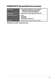
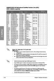
x 9.6 in . xiii SABERTOOTH 55i specifications summary BIOS features Manageability Support DVD contents Form factor 16 Mb Flash ROM, AMI BIOS, PnP, DMI 2.0, WfM 2.0, SM BIOS 2.5, ACPI 2.0a, Multi-language BIOS, ASUS EZ Flash 2, ASUS CrashFree BIOS 3 WfM 2.0, DMI 2.0, WOL by PME, WOR by PME, PXE Drivers ASUS Utilities ASUS Update Anti-virus software (OEM version) ATX form factor: 12 in . (30.5 cm x 24.4 cm) *Specifications are subject to change without notice.
x 9.6 in . xiii SABERTOOTH 55i specifications summary BIOS features Manageability Support DVD contents Form factor 16 Mb Flash ROM, AMI BIOS, PnP, DMI 2.0, WfM 2.0, SM BIOS 2.5, ACPI 2.0a, Multi-language BIOS, ASUS EZ Flash 2, ASUS CrashFree BIOS 3 WfM 2.0, DMI 2.0, WOL by PME, WOR by PME, PXE Drivers ASUS Utilities ASUS Update Anti-virus software (OEM version) ATX form factor: 12 in . (30.5 cm x 24.4 cm) *Specifications are subject to change without notice.
User Manual
Page 18
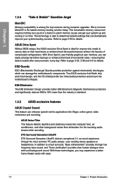
... clear human dialogue even with ease. 1-4 Chapter 1: Product Introduction The ASUS exclusive Anti-Static chip and circuit design, and the I/O shield provide four times better protection and ensure the motherboard's lifespan. ASUS Noise Filter This feature detects repetitive and stationary noises like Skype, online... fans, air conditioners, and other background noises then eliminates it in no more. Guardian Angel MemOK! ASUS Drive Xpert Without BIOS setups, the ASUS exclusive Drive Xpert is able to patch memory issues and get your existing stereo speakers or headphones. With...
... clear human dialogue even with ease. 1-4 Chapter 1: Product Introduction The ASUS exclusive Anti-Static chip and circuit design, and the I/O shield provide four times better protection and ensure the motherboard's lifespan. ASUS Noise Filter This feature detects repetitive and stationary noises like Skype, online... fans, air conditioners, and other background noises then eliminates it in no more. Guardian Angel MemOK! ASUS Drive Xpert Without BIOS setups, the ASUS exclusive Drive Xpert is able to patch memory issues and get your existing stereo speakers or headphones. With...
User Manual
Page 19
... and shields it against Electronic Magnetic Interference (EMI). ASUS Q-Connector ASUS Q-Connector allows you configure your motherboard. The localized BIOS setup menu helps you to easily connect or disconnect the chassis front panel cables to the motherboard. ASUS SABERTOOTH 55i 1-5 ASUS O.C. Profile The motherboard features the ASUS O.C. Refer to page 2-39 for details. ASUS Onboard Switch With an easy press during overclocking...
... and shields it against Electronic Magnetic Interference (EMI). ASUS Q-Connector ASUS Q-Connector allows you configure your motherboard. The localized BIOS setup menu helps you to easily connect or disconnect the chassis front panel cables to the motherboard. ASUS SABERTOOTH 55i 1-5 ASUS O.C. Profile The motherboard features the ASUS O.C. Refer to page 2-39 for details. ASUS Onboard Switch With an easy press during overclocking...
User Manual
Page 31
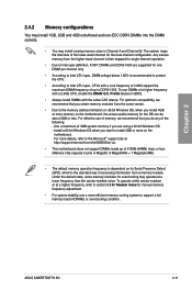
.../Mb = 1 Megabyte/MB). • The default memory operation frequency is dependent on the motherboard, the actual usable memory for the OS can be about 3GB or less. For more on the motherboard. ASUS SABERTOOTH 55i 2-11 Profile feature in Channel A and Channel B. Chapter 2 2.4.2 Memory configurations You may ...memory frequency adjustment. • For system stability, use DIMMs of the lower-sized channel for overclocking may install varying memory sizes in BIOS. • Always install DIMMs with a 2.66G CPU, enable the DRAM O.C. Any excess memory from the higher-sized channel is...
.../Mb = 1 Megabyte/MB). • The default memory operation frequency is dependent on the motherboard, the actual usable memory for the OS can be about 3GB or less. For more on the motherboard. ASUS SABERTOOTH 55i 2-11 Profile feature in Channel A and Channel B. Chapter 2 2.4.2 Memory configurations You may ...memory frequency adjustment. • For system stability, use DIMMs of the lower-sized channel for overclocking may install varying memory sizes in BIOS. • Always install DIMMs with a 2.66G CPU, enable the DRAM O.C. Any excess memory from the higher-sized channel is...
User Manual
Page 32
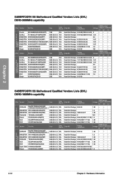
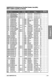
...Kit of 2) N/A Heat-Sink Package 8-8-8-24(1866-8-8-8-24) 1.9 • • • 2-12 Chapter 2: Hardware information Timing Lable(Bios) DIMM socket Voltage support (Optional) A* B* C* CORSAIR BoxP/N:TW3X4G1800C8DF (CM3X2G1800C8D)(XMP)Ver4.1 4GB (Kit of 2) N/A Heat-Sink Package ...8226; • SABERTOOTH 55i Motherboard Qualified Vendors Lists (QVL) DDR3-1800MHz capability CPU Vendor Part No. Size Chip Brand Chip NO. Chapter 2 SABERTOOTH 55i Motherboard Qualified Vendors Lists (QVL) DDR3-2000MHz capability CPU Vendor Part No. Timing Lable(Bios) DIMM socket Voltage...
...Kit of 2) N/A Heat-Sink Package 8-8-8-24(1866-8-8-8-24) 1.9 • • • 2-12 Chapter 2: Hardware information Timing Lable(Bios) DIMM socket Voltage support (Optional) A* B* C* CORSAIR BoxP/N:TW3X4G1800C8DF (CM3X2G1800C8D)(XMP)Ver4.1 4GB (Kit of 2) N/A Heat-Sink Package ...8226; • SABERTOOTH 55i Motherboard Qualified Vendors Lists (QVL) DDR3-1800MHz capability CPU Vendor Part No. Size Chip Brand Chip NO. Chapter 2 SABERTOOTH 55i Motherboard Qualified Vendors Lists (QVL) DDR3-2000MHz capability CPU Vendor Part No. Timing Lable(Bios) DIMM socket Voltage...
User Manual
Page 33
Timing Lable(Bios) A-DATA AD31600E001GMU 3GB (Kit of 3) N/A Heat-Sink Package 8-8-8-24(1333-9-9-9-24) A-DATA AD31600F002GMU(XMP) 6GB (Kit of 3) N/A Heat-Sink Package 7-7-7-20(1333...8226; • • 1.65 • • • 1.9 •• 2.0 •• 1.65 • • • N/A ••• 1.9 ••• 1.9 ••• ASUS SABERTOOTH 55i 2-13 Capability for CPU at 2.66GHz Chapter 2 SABERTOOTH 55i Motherboard Qualified Vendors Lists (QVL) DDR3-1600MHz capability CPU Vendor Part No. Size Chip Brand Chip NO.
Timing Lable(Bios) A-DATA AD31600E001GMU 3GB (Kit of 3) N/A Heat-Sink Package 8-8-8-24(1333-9-9-9-24) A-DATA AD31600F002GMU(XMP) 6GB (Kit of 3) N/A Heat-Sink Package 7-7-7-20(1333...8226; • • 1.65 • • • 1.9 •• 2.0 •• 1.65 • • • N/A ••• 1.9 ••• 1.9 ••• ASUS SABERTOOTH 55i 2-13 Capability for CPU at 2.66GHz Chapter 2 SABERTOOTH 55i Motherboard Qualified Vendors Lists (QVL) DDR3-1600MHz capability CPU Vendor Part No. Size Chip Brand Chip NO.
User Manual
Page 34
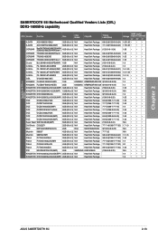
... 2GB DS 2GB DS A-DATA A-DATA N/A ELPIDA Apacer ELPIDA ELPIDA Apacer ELPIDA Chip NO. Chapter 2 SABERTOOTH 55i Motherboard Qualified Vendors Lists (QVL) DDR3-1600MHz capability (continued) CPU Vendor Part No. A-DATA A-DATA A-DATA... • • ••• 1.9 ••• 1.9 •• 1.9 ••• SABERTOOTH 55i Motherboard Qualified Vendors Lists (QVL) DDR3-1333MHz capability Vendor Part No. Timing Lable(Bios) DIMM socket Voltage support (Optional) A* B* C* AD30908C8D-15IG (1333-9-9-9-24) N/A •• • AD30908C8D-15IG...
... 2GB DS 2GB DS A-DATA A-DATA N/A ELPIDA Apacer ELPIDA ELPIDA Apacer ELPIDA Chip NO. Chapter 2 SABERTOOTH 55i Motherboard Qualified Vendors Lists (QVL) DDR3-1600MHz capability (continued) CPU Vendor Part No. A-DATA A-DATA A-DATA... • • ••• 1.9 ••• 1.9 •• 1.9 ••• SABERTOOTH 55i Motherboard Qualified Vendors Lists (QVL) DDR3-1333MHz capability Vendor Part No. Timing Lable(Bios) DIMM socket Voltage support (Optional) A* B* C* AD30908C8D-15IG (1333-9-9-9-24) N/A •• • AD30908C8D-15IG...
User Manual
Page 35
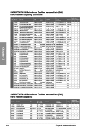
Chapter 2 SABERTOOTH 55i Motherboard Qualified Vendors Lists (QVL) DDR3-1333MHz capability (continued) Vendor Part No. Size SS/ Chip DS Brand Chip NO. Timing Lable(Bios) Voltage CORSAIR TR3X3G1333C9 (Ver2.1) 3GB (Kit of 3) SS CORSAIR BoxP/N:TWIN3X2048-1333C9 (CM3X1024-1333C9)Ver1.1 2GB (Kit of 2) DS CORSAIR BoxP/N:TW3X4G1333C9DHX (CM3X2048-... 9-9-9-24(1066-7-7-7-20) 1.65 9(1333-9-9-9-24) N/A DIMM socket support (Optional) A* B* C* •• • •• • •• •• • •• • ASUS SABERTOOTH 55i 2-15
Chapter 2 SABERTOOTH 55i Motherboard Qualified Vendors Lists (QVL) DDR3-1333MHz capability (continued) Vendor Part No. Size SS/ Chip DS Brand Chip NO. Timing Lable(Bios) Voltage CORSAIR TR3X3G1333C9 (Ver2.1) 3GB (Kit of 3) SS CORSAIR BoxP/N:TWIN3X2048-1333C9 (CM3X1024-1333C9)Ver1.1 2GB (Kit of 2) DS CORSAIR BoxP/N:TW3X4G1333C9DHX (CM3X2048-... 9-9-9-24(1066-7-7-7-20) 1.65 9(1333-9-9-9-24) N/A DIMM socket support (Optional) A* B* C* •• • •• • •• •• • •• • ASUS SABERTOOTH 55i 2-15
User Manual
Page 36
... Chapter 2: Hardware information SABERTOOTH 55i Motherboard Qualified Vendors Lists (QVL) DDR3-1066MHz capability Vendor Part No. Single-sided DS - To use DIMMs of a higher frequency with a core frequency of 2.66G support the maximum DIMM frequency of individual CPUs. • According to DDR3-1333. Profile feature in BIOS. • Visit the ASUS website for one DIMM...
... Chapter 2: Hardware information SABERTOOTH 55i Motherboard Qualified Vendors Lists (QVL) DDR3-1066MHz capability Vendor Part No. Single-sided DS - To use DIMMs of a higher frequency with a core frequency of 2.66G support the maximum DIMM frequency of individual CPUs. • According to DDR3-1333. Profile feature in BIOS. • Visit the ASUS website for one DIMM...
User Manual
Page 38
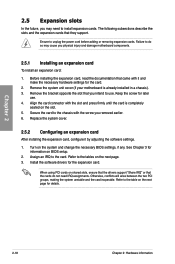
...3. When using PCI cards on the slot. 5. Chapter 2 2.5 Expansion slots In the future, you may cause you physical injury and damage motherboard components. 2.5.1 Installing an expansion card To install an expansion card: 1. Replace the system cover. 2.5.2 Configuring an expansion card After installing the expansion...or removing expansion cards. Install the software drivers for information on the next page for the card. 2. Failure to the table on BIOS setup. 2. See Chapter 3 for the expansion card. Turn on the next page. 3. Otherwise, conflicts will arise between the two...
...3. When using PCI cards on the slot. 5. Chapter 2 2.5 Expansion slots In the future, you may cause you physical injury and damage motherboard components. 2.5.1 Installing an expansion card To install an expansion card: 1. Replace the system cover. 2.5.2 Configuring an expansion card After installing the expansion...or removing expansion cards. Install the software drivers for information on the next page for the card. 2. Failure to the table on BIOS setup. 2. See Chapter 3 for the expansion card. Turn on the next page. 3. Otherwise, conflicts will arise between the two...
User Manual
Page 42
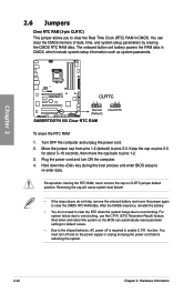
...battery and move the cap back to overclocking. function. Keep the cap on CLRTC jumper default position. Hold down and reboot the system so the BIOS can clear the CMOS memory of date, time, and system setup parameters by erasing the CMOS RTC RAM data. 2.6 Jumpers Clear RTC RAM (3-...Clock (RTC) RAM in CMOS, which include system setup information such as system passwords. Shut down the key during the boot process and enter BIOS setup to enable C.P.R. Plug the power cord and turn off is required to re-enter data. You can automatically reset parameter settings to default ...
...battery and move the cap back to overclocking. function. Keep the cap on CLRTC jumper default position. Hold down and reboot the system so the BIOS can clear the CMOS memory of date, time, and system setup parameters by erasing the CMOS RTC RAM data. 2.6 Jumpers Clear RTC RAM (3-...Clock (RTC) RAM in CMOS, which include system setup information such as system passwords. Shut down the key during the boot process and enter BIOS setup to enable C.P.R. Plug the power cord and turn off is required to re-enter data. You can automatically reset parameter settings to default ...
User Manual
Page 44
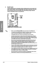
...Windows® OS environment. • During the tuning process, the system loads and tests failsafe memory settings. Replace the DIMMs with the motherboard may cause system boot failure, and the DRAM_LED near the MemOK! switch to begin automatic memory compatibility tuning for the system to its default...Installing DIMMs that you download and update to boot after turning on the ASUS website at www.asus.com after using the MemOK! If the installed DIMMs still fail to the latest BIOS version from the ASUS website at www.asus.com. • If you turn off the computer and unplug the ...
...Windows® OS environment. • During the tuning process, the system loads and tests failsafe memory settings. Replace the DIMMs with the motherboard may cause system boot failure, and the DRAM_LED near the MemOK! switch to begin automatic memory compatibility tuning for the system to its default...Installing DIMMs that you download and update to boot after turning on the ASUS website at www.asus.com after using the MemOK! If the installed DIMMs still fail to the latest BIOS version from the ASUS website at www.asus.com. • If you turn off the computer and unplug the ...

User Manual
Page 45
.... • The system may need a better cooling system (for extra-high overvoltage ability, use the BIOS items first to adjust the desired DRAM performance. ASUS SABERTOOTH 55i 2-25 DRAM overvoltage setting switch (OV_DRAM) This switch allows you change the settings for example, a water...-cooling system) to enable or disable the advanced DRAM overvoltage settings in BIOS. Chapter 2 4. Default Enable OV (red) ...
.... • The system may need a better cooling system (for extra-high overvoltage ability, use the BIOS items first to adjust the desired DRAM performance. ASUS SABERTOOTH 55i 2-25 DRAM overvoltage setting switch (OV_DRAM) This switch allows you change the settings for example, a water...-cooling system) to enable or disable the advanced DRAM overvoltage settings in BIOS. Chapter 2 4. Default Enable OV (red) ...
User Manual
Page 46
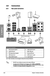
... insert a different connector to the external SATA port. • To enable external SATA device hot-plugging, set the J-Micron eSATA/PATA Controller item in the BIOS setting to section 3.6.3 Onboard Devices Configuration for details. 2-26 Chapter 2: Hardware information Refer to [AHCI Mode], and then reboot the system. LAN (RJ-45) port...
... insert a different connector to the external SATA port. • To enable external SATA device hot-plugging, set the J-Micron eSATA/PATA Controller item in the BIOS setting to section 3.6.3 Onboard Devices Configuration for details. 2-26 Chapter 2: Hardware information Refer to [AHCI Mode], and then reboot the system. LAN (RJ-45) port...
User Manual
Page 51
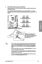
2. In Standard IDE mode, you intend to section 4.4 RAID configurations or the manual bundled in the motherboard support DVD. • You must install Windows® XP Service Pack 2 or later version before using these connectors. If you can create a RAID 0, 1, ... 3.4.2 Storage Configuration for details. • Before creating a RAID set, refer to create a Serial ATA RAID set the Configure SATA as in the BIOS to [RAID]. ASUS SABERTOOTH 55i 2-31 The Serial ATA RAID feature is available only if you can connect Serial ATA boot/data hard disk drives to these connectors, set...
2. In Standard IDE mode, you intend to section 4.4 RAID configurations or the manual bundled in the motherboard support DVD. • You must install Windows® XP Service Pack 2 or later version before using these connectors. If you can create a RAID 0, 1, ... 3.4.2 Storage Configuration for details. • Before creating a RAID set, refer to create a Serial ATA RAID set the Configure SATA as in the BIOS to [RAID]. ASUS SABERTOOTH 55i 2-31 The Serial ATA RAID feature is available only if you can connect Serial ATA boot/data hard disk drives to these connectors, set...
User Manual
Page 56
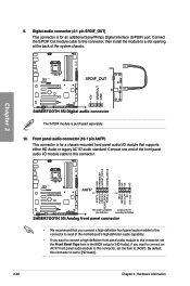
...PDIF module is for a chassis-mounted front panel audio I /O module cable to this connector, set to a slot opening at the back of the motherboard's high-definition audio capability. • If you want to connect a high-definition front panel audio module to this connector, set the Front Panel ...Type item in the BIOS setup to [AC97]. By default, this connector, then install the module to [HD Audio]. 2-36 Chapter 2: Hardware information Digital audio connector (4-1...
...PDIF module is for a chassis-mounted front panel audio I /O module cable to this connector, set to a slot opening at the back of the motherboard's high-definition audio capability. • If you want to connect a high-definition front panel audio module to this connector, set the Front Panel ...Type item in the BIOS setup to [AC97]. By default, this connector, then install the module to [HD Audio]. 2-36 Chapter 2: Hardware information Digital audio connector (4-1...


