User Guide
Page 3
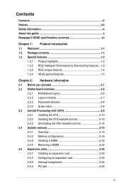
...iii Notices...viii Safety information ix About this guide x Rampage II GENE specifications summary xii Chapter 1: Product introduction 1.1 Welcome 1-1 1.2 Package contents 1-1 1.3 Special features 1-2 1.3.1 Product highlights 1-2 1.3.2 ROG Intelligent Performance & Overclocking features... 1-3 1.3.3 ROG unique features 1-4 1.3.4 ASUS special features 1-5 Chapter 2: Hardware information 2.1 Before you proceed 2-1 2.2 Motherboard overview 2-6 2.2.1 Motherboard layout 2-6 2.2.2 Layout contents 2-7 2.2.3 Placement direction 2-8 2.2.4 Screw holes 2-8 2.3 Central Processing Unit (CPU...
...iii Notices...viii Safety information ix About this guide x Rampage II GENE specifications summary xii Chapter 1: Product introduction 1.1 Welcome 1-1 1.2 Package contents 1-1 1.3 Special features 1-2 1.3.1 Product highlights 1-2 1.3.2 ROG Intelligent Performance & Overclocking features... 1-3 1.3.3 ROG unique features 1-4 1.3.4 ASUS special features 1-5 Chapter 2: Hardware information 2.1 Before you proceed 2-1 2.2 Motherboard overview 2-6 2.2.1 Motherboard layout 2-6 2.2.2 Layout contents 2-7 2.2.3 Placement direction 2-8 2.2.4 Screw holes 2-8 2.3 Central Processing Unit (CPU...

User Guide
Page 30
2.2 Motherboard overview 2.2.1 Motherboard layout 2-6 Chapter 2: Hardware information
2.2 Motherboard overview 2.2.1 Motherboard layout 2-6 Chapter 2: Hardware information
User Guide
Page 31
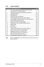
... rear panel connectors and internal connectors. ROG Rampage II GENE 2-7 System panel connector (20-8 pin PANEL) 10. Reset switch 13. Thermal sensor cable connectors (2-pin OPT_TEMP1-2) 15. switch 12. Digital audio connector (4-1 pin SPDIF_OUT) 17. LGA1366 CPU Socket 4. USB910; Optical drive audio connector (4-pin CD) 19. 2.2.2 Layout contents Connectors/Jumpers/Switches/Slots 1. CPU, chassis...
... rear panel connectors and internal connectors. ROG Rampage II GENE 2-7 System panel connector (20-8 pin PANEL) 10. Reset switch 13. Thermal sensor cable connectors (2-pin OPT_TEMP1-2) 15. switch 12. Digital audio connector (4-1 pin SPDIF_OUT) 17. LGA1366 CPU Socket 4. USB910; Optical drive audio connector (4-pin CD) 19. 2.2.2 Layout contents Connectors/Jumpers/Switches/Slots 1. CPU, chassis...

User Guide
Page 162
... to the goldfingers on the slots. 4. Connect two independent auxiliary power sources from the power supply to the graphics card. The graphics cards and the motherboard layout may vary with models, but the installation steps remain the same. 1. Ensure that the connector is firmly in place. Prepare two CrossFireX-ready graphics cards...
... to the goldfingers on the slots. 4. Connect two independent auxiliary power sources from the power supply to the graphics card. The graphics cards and the motherboard layout may vary with models, but the installation steps remain the same. 1. Ensure that the connector is firmly in place. Prepare two CrossFireX-ready graphics cards...

User Guide
Page 166
... cards are for reference only. 5.2.2 Installing SLI-ready graphics cards The following pictures are properly seated on each graphics card. The graphics cards and the motherboard layout may vary with models, but the installation steps remain the same. 1. Prepare two SLI-ready graphics cards. 2. Insert the two graphics card into the PCIEX16...
... cards are for reference only. 5.2.2 Installing SLI-ready graphics cards The following pictures are properly seated on each graphics card. The graphics cards and the motherboard layout may vary with models, but the installation steps remain the same. 1. Prepare two SLI-ready graphics cards. 2. Insert the two graphics card into the PCIEX16...

