
User Guide
Page 19
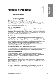
...174; Goren" i7 processors. It also features backward compatibility with its GPU, dual-channel DDR4 memory slots and PCI Express 2.0/3.0 expansion slots. ASUS RAMPAGE V EXTREME 1-1 PCIe 3.0 Ready The PCI Express bus standard delivers improved encoding for twice the performance of the same speed. PCIe 3.0 X4 M.2 Support...for a x16 link reaches a maximum of 32Gb/s, double the 16Gb/s of PCIe 2.0 in the LGA2011-v3 package. Refer to www.asus.com for updated details. 3-Way/4-way/Quad-GPU SLITM and CrossFireXTM Support This motherboard features Intel's powerful new X99 platform and optimizes ...
...174; Goren" i7 processors. It also features backward compatibility with its GPU, dual-channel DDR4 memory slots and PCI Express 2.0/3.0 expansion slots. ASUS RAMPAGE V EXTREME 1-1 PCIe 3.0 Ready The PCI Express bus standard delivers improved encoding for twice the performance of the same speed. PCIe 3.0 X4 M.2 Support...for a x16 link reaches a maximum of 32Gb/s, double the 16Gb/s of PCIe 2.0 in the LGA2011-v3 package. Refer to www.asus.com for updated details. 3-Way/4-way/Quad-GPU SLITM and CrossFireXTM Support This motherboard features Intel's powerful new X99 platform and optimizes ...
User Guide
Page 21
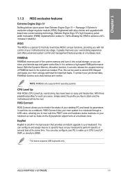
...allows you like to wake up in real-time via a notebook. KeyBot KeyBot is a special IC that provides an instant upgrade to BIOS. ASUS RAMPAGE V EXTREME 1-3 ROG Connect links your notebook as well as needed. You can configure and assign macros to view real-time POST code and hardware status ... Digi+ IV - Plus, this can store your motherboard at a hardware level. This feature supports USB keyboards only. Rampage V Extreme's exclusive voltage-regulator module (VRM). With the Dynamic Memory Allocation function, it into actual storage, so you to specific keys on -the-...
...allows you like to wake up in real-time via a notebook. KeyBot KeyBot is a special IC that provides an instant upgrade to BIOS. ASUS RAMPAGE V EXTREME 1-3 ROG Connect links your notebook as well as needed. You can configure and assign macros to view real-time POST code and hardware status ... Digi+ IV - Plus, this can store your motherboard at a hardware level. This feature supports USB keyboards only. Rampage V Extreme's exclusive voltage-regulator module (VRM). With the Dynamic Memory Allocation function, it into actual storage, so you to specific keys on -the-...

User Guide
Page 23
ASUS RAMPAGE V EXTREME 1-5 1.1.4 ASUS special features Al Suite 3 CU With its user-friendly interface, ASUS Al Suite 3 consolidates all the exclusive ASUS features into a single software package. Simply install a USB storage device containing the BIOS file, press the BIOS Flashback button for UEFI BIOS updates and download ...
ASUS RAMPAGE V EXTREME 1-5 1.1.4 ASUS special features Al Suite 3 CU With its user-friendly interface, ASUS Al Suite 3 consolidates all the exclusive ASUS features into a single software package. Simply install a USB storage device containing the BIOS file, press the BIOS Flashback button for UEFI BIOS updates and download ...
User Guide
Page 25
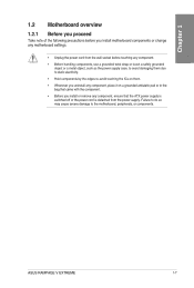
... the power supply. Failure to do so may cause severe damage to avoid touching the ICs on them. • Whenever you uninstall any motherboard settings. ASUS RAMPAGE V EXTREME 1-7 1.2 Motherboard overview 1.2.1 Before you proceed IcLu Take note of the following precautions before touching any component. • Before handling components, use a grounded wrist strap or...
... the power supply. Failure to do so may cause severe damage to avoid touching the ICs on them. • Whenever you uninstall any motherboard settings. ASUS RAMPAGE V EXTREME 1-7 1.2 Motherboard overview 1.2.1 Before you proceed IcLu Take note of the following precautions before touching any component. • Before handling components, use a grounded wrist strap or...
User Guide
Page 27
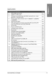
... 1-25 1-38 1-28 1-21 1-34 1-21 1-26 1-24 1-23 1-22 1-45 1-37 1-41 1-35 1-36 1-25 1-23 1-43 1-41 1-38 1-36 1-24 1-40 1-40 1-44 ASUS RAMPAGE V EXTREME 1-9 button (MemOK!) 15 Probelt 16 USB 3.0 connector (20-1 pin USB3_34) 17 M.2 connector 18 Intel® X99 Serial ATA 6 Gb/s connectors (7-pin SATA6G_1-10; Layout contents...
... 1-25 1-38 1-28 1-21 1-34 1-21 1-26 1-24 1-23 1-22 1-45 1-37 1-41 1-35 1-36 1-25 1-23 1-43 1-41 1-38 1-36 1-24 1-40 1-40 1-44 ASUS RAMPAGE V EXTREME 1-9 button (MemOK!) 15 Probelt 16 USB 3.0 connector (20-1 pin USB3_34) 17 M.2 connector 18 Intel® X99 Serial ATA 6 Gb/s connectors (7-pin SATA6G_1-10; Layout contents...
User Guide
Page 29
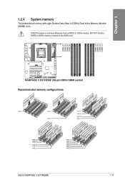
... DIMM_A1 DIMILA1 DIMALC1 z DIMM_A1 DIMM_A2 DIMM_B1 DIMM_D2 DIMNLD1 DIMM_C1 • ~ ~`/~~ DIMM_A1 DIMM_B1 DIMMJ)1 DIMM_C1 DEG DIMM_A1 DIMM_A2 DIMI D1 DIMMJE12 DIMILD2 DIMILD1 DIMILC2 DIMM_C1 O oo ASUS RAMPAGE V EXTREME 1-11 U )- 1.2.4 System memory The motherboard comes with eight Double Data Rate 4 (DDR4) Dual Inline Memory Module CO (DIMM) slots. a IQ .0 (!\ A DDR4 module is notched differently...
... DIMM_A1 DIMILA1 DIMALC1 z DIMM_A1 DIMM_A2 DIMM_B1 DIMM_D2 DIMNLD1 DIMM_C1 • ~ ~`/~~ DIMM_A1 DIMM_B1 DIMMJ)1 DIMM_C1 DEG DIMM_A1 DIMM_A2 DIMI D1 DIMMJE12 DIMILD2 DIMILD1 DIMILC2 DIMM_C1 O oo ASUS RAMPAGE V EXTREME 1-11 U )- 1.2.4 System memory The motherboard comes with eight Double Data Rate 4 (DDR4) Dual Inline Memory Module CO (DIMM) slots. a IQ .0 (!\ A DDR4 module is notched differently...
User Guide
Page 31
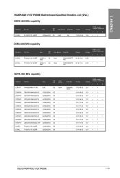
...-36 1.2V • • 15-17-17-36 1.2V • • 17-18-18-35 1.2V • • 17-18-18-35 1.2V • • ASUS RAMPAGE V EXTREME 1-13 Chip NO. Size F4-3000C16O-16GRR 16GB ( 4x SS 4GB) F4-3000C16O-32GRR 32GB ( 4x DS 8GB) Chlp Brand Chlp NO. G.SKILL F4-3300C17O...
...-36 1.2V • • 15-17-17-36 1.2V • • 17-18-18-35 1.2V • • 17-18-18-35 1.2V • • ASUS RAMPAGE V EXTREME 1-13 Chip NO. Size F4-3000C16O-16GRR 16GB ( 4x SS 4GB) F4-3000C16O-32GRR 32GB ( 4x DS 8GB) Chlp Brand Chlp NO. G.SKILL F4-3300C17O...

User Guide
Page 35
ASUS RAMPAGE V EXTREME 1-17 settings in the BIOS for the hyper DIMM support. • Visit the ASUS website for better compatibility. Supports four (4) modules inserted into all slots as fully-loaded quad-channel memory configurations. • ASUS exclusively provides hyper DIMM support function. • Hyper DIMM support is subject to the physical characteristics of individual CPUs...
ASUS RAMPAGE V EXTREME 1-17 settings in the BIOS for the hyper DIMM support. • Visit the ASUS website for better compatibility. Supports four (4) modules inserted into all slots as fully-loaded quad-channel memory configurations. • ASUS exclusively provides hyper DIMM support function. • Hyper DIMM support is subject to the physical characteristics of individual CPUs...

User Guide
Page 37
..., both the SATAEXPRESS_E1, USB3_E910 ports, and the PCIE_X1_1 slot will be disabled when using a 28-LANE CPU. • The PCIE_X4_1 (gray) slot shares bandwidth with M.2 x 4. ASUS RAMPAGE V EXTREME 1-19 • We recommend that you provide sufficient power when running CrossFireXTM or SLI cu mode. • While running at four heavy loaded VGA cards...
..., both the SATAEXPRESS_E1, USB3_E910 ports, and the PCIE_X1_1 slot will be disabled when using a 28-LANE CPU. • The PCIE_X4_1 (gray) slot shares bandwidth with M.2 x 4. ASUS RAMPAGE V EXTREME 1-19 • We recommend that you provide sufficient power when running CrossFireXTM or SLI cu mode. • While running at four heavy loaded VGA cards...
User Guide
Page 39
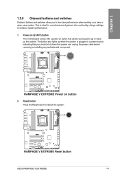
The button also lights up the system. FIPPAPPON V EXTREMI I7 O EOJ Z = IZ -flJ1=1=CallaLLO =IA RAMPAGE V EXTREME Power on a bare or cu open-case system. Power-on (START) button The motherboard comes with a power-on button that you should shut down the ... is plugged to a power source indicating that allows you to reboot the system. • Die 7 RillAPiNiff V KXTFINIMI i7,0 LEE De LEonoio=aeil r-r-IrDro mom =Et RAMPAGE V EXTREME Reset button ASUS RAMPAGE V EXTREME 1-21
The button also lights up the system. FIPPAPPON V EXTREMI I7 O EOJ Z = IZ -flJ1=1=CallaLLO =IA RAMPAGE V EXTREME Power on a bare or cu open-case system. Power-on (START) button The motherboard comes with a power-on button that you should shut down the ... is plugged to a power source indicating that allows you to reboot the system. • Die 7 RillAPiNiff V KXTFINIMI i7,0 LEE De LEonoio=aeil r-r-IrDro mom =Et RAMPAGE V EXTREME Reset button ASUS RAMPAGE V EXTREME 1-21
User Guide
Page 41
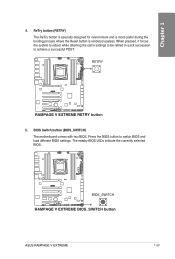
... and load different BIOS settings. RETRY lz.] ,,..... -I 7 I I7O L E o Ogilt Ca= ii BIOS_SWITCH 2k 0. 0 T' PI • • RAMPAGE V EXTREME BIOS_SWITCH button ASUS RAMPAGE V EXTREME 1-23 BIOS Switch button (BIOS_SWITCH) The motherboard comes with two BIOS. b J AIM I= I I IL O .0 ou ° O ET, RAMPAGE V EXTREME RETRY button 5. ReTry button (RETRY) The ReTry button is specially designed for overclockers and is most...
... and load different BIOS settings. RETRY lz.] ,,..... -I 7 I I7O L E o Ogilt Ca= ii BIOS_SWITCH 2k 0. 0 T' PI • • RAMPAGE V EXTREME BIOS_SWITCH button ASUS RAMPAGE V EXTREME 1-23 BIOS Switch button (BIOS_SWITCH) The motherboard comes with two BIOS. b J AIM I= I I IL O .0 ou ° O ET, RAMPAGE V EXTREME RETRY button 5. ReTry button (RETRY) The ReTry button is specially designed for overclockers and is most...
User Guide
Page 43
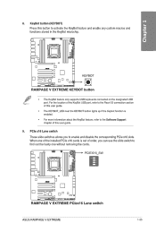
... KeyBot feature, refer to the Software Support chapter of order, you to :1: El U ®e DECE T u i° AIM NIV417 r'7 O 7 E KEYBOT • ramo===i • • RAMPAGE V EXTREME KEYBOT button • The KeyBot feature only supports USB keyboards connected on the designated USB port. For the location of the KeyBot USB port, refer...out of this button to find out the faulty one without removing the cards. ®Re PCIEX16_SW ANIM • =C E O 0 7 7 E7Jag 4nno!ODEL.J...A__I nrmErcomEmomxg RAMPAGE V EXTREME PCIex16 Lane switch ASUS RAMPAGE V EXTREME 1-25
... KeyBot feature, refer to the Software Support chapter of order, you to :1: El U ®e DECE T u i° AIM NIV417 r'7 O 7 E KEYBOT • ramo===i • • RAMPAGE V EXTREME KEYBOT button • The KeyBot feature only supports USB keyboards connected on the designated USB port. For the location of the KeyBot USB port, refer...out of this button to find out the faulty one without removing the cards. ®Re PCIEX16_SW ANIM • =C E O 0 7 7 E7Jag 4nno!ODEL.J...A__I nrmErcomEmomxg RAMPAGE V EXTREME PCIex16 Lane switch ASUS RAMPAGE V EXTREME 1-25
User Guide
Page 45
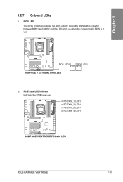
U CI I IsQ EC) LLD:, BIOS_LED1 0 EEO ==70mosommol RAMPAGE V EXTREME BIOS_LED U BIOS_LED2 2. BIOS LED The BIOS LEDs help indicate the BIOS activity. PCIE Lane LED indicator Indicates the PCIE lane used. Press the BIOS button to switch between BIOS1 and BIOS2 and the LED lights up when the corresponding BIOS is in IQ .0 use. o-lamilottt====rom,oot RAMPAGE V EXTREME PCIex16 LED ASUS RAMPAGE V EXTREME 1-27 1.2.7 Onboard LEDs IL 1. PCIEX16_1_LED1 o PCIEX16_2_LED1 o PCIEX16_3_LED1 o PCIEX16_4_LED1 ion „ O, un.
U CI I IsQ EC) LLD:, BIOS_LED1 0 EEO ==70mosommol RAMPAGE V EXTREME BIOS_LED U BIOS_LED2 2. BIOS LED The BIOS LEDs help indicate the BIOS activity. PCIE Lane LED indicator Indicates the PCIE lane used. Press the BIOS button to switch between BIOS1 and BIOS2 and the LED lights up when the corresponding BIOS is in IQ .0 use. o-lamilottt====rom,oot RAMPAGE V EXTREME PCIex16 LED ASUS RAMPAGE V EXTREME 1-27 1.2.7 Onboard LEDs IL 1. PCIEX16_1_LED1 o PCIEX16_2_LED1 o PCIEX16_3_LED1 o PCIEX16_4_LED1 ion „ O, un.
User Guide
Page 47
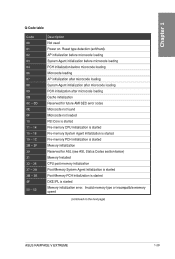
... memory type or incompatible memory speed (continued on . ri Q-Code table Code Description aIac.au. IQ 00 Not used .0 U 01 Power on the next page) ASUS RAMPAGE V EXTREME 1-29
... memory type or incompatible memory speed (continued on . ri Q-Code table Code Description aIac.au. IQ 00 Not used .0 U 01 Power on the next page) ASUS RAMPAGE V EXTREME 1-29

User Guide
Page 49
... Bus Assign Resources Console Output devices connect Console input devices connect Super 1O Initialization USB initialization is started USB Reset (continued on the next page) ASUS RAMPAGE V EXTREME 1-31
... Bus Assign Resources Console Output devices connect Console input devices connect Super 1O Initialization USB initialization is started USB Reset (continued on the next page) ASUS RAMPAGE V EXTREME 1-31

User Guide
Page 51
Interrupt controller is in APIC mode. Interrupt controller is waking up from the S3 sleep state System is in PIC mode. ASUS RAMPAGE V EXTREME 1-33 Out of the Architectural Protocols are found D7 No Console Input Devices are not available U D4 PCI resource allocation error. System has transitioned into ...
Interrupt controller is in APIC mode. Interrupt controller is waking up from the S3 sleep state System is in PIC mode. ASUS RAMPAGE V EXTREME 1-33 Out of the Architectural Protocols are found D7 No Console Input Devices are not available U D4 PCI resource allocation error. System has transitioned into ...
User Guide
Page 53
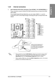
... are set to create a Serial ATA RAID array using these connectors, set the SATA Mode item in the motherboard support DVD. ASUS RAMPAGE V EXTREME 1-35 SATAEXPRESS_1) These connectors connect to SATA device. RAMPAGE V EXTREME Intel® SATA 6 Gb/s connectors SATA6G_5 SATA6G_6 OND IIGATA_TXP5 RSAGUIENS GNG FIGOTA_MG. RSATA_GX1.2 GM SATA6G_3 MID 1.45/0,7,78 FIGAT&TXN3 OND...
... are set to create a Serial ATA RAID array using these connectors, set the SATA Mode item in the motherboard support DVD. ASUS RAMPAGE V EXTREME 1-35 SATAEXPRESS_1) These connectors connect to SATA device. RAMPAGE V EXTREME Intel® SATA 6 Gb/s connectors SATA6G_5 SATA6G_6 OND IIGATA_TXP5 RSAGUIENS GNG FIGOTA_MG. RSATA_GX1.2 GM SATA6G_3 MID 1.45/0,7,78 FIGAT&TXN3 OND...
User Guide
Page 55
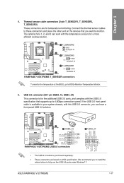
... and complies with this USB 3.0 connector, you to install the related driver to fully use the USB 3.0 ports under Windows ® 7. InULPI_SSTX- GNI) D+ RAMPAGE V EXTREME USB3.0 connectors 0 USB3_34 g g ..... 2 55 c.) 4 44 4,4 2 II; 4 ' illiiiiii i i i i i i i i i i .., ... D. The optional fans 1, 2, and 3 can have a front panel USB 3.0 solution. IntA_P2_0+ -• . - Pi.- ASUS RAMPAGE V EXTREME 1-37 IntA_P2_8STX--• .- Connect the thermal sensor cables to to monitor. IntA_Pl_SSTX+ IntA_P2_SSTX+-• . - INA P1_SSRX., IntA_P2_SSR)(+-....
... and complies with this USB 3.0 connector, you to install the related driver to fully use the USB 3.0 ports under Windows ® 7. InULPI_SSTX- GNI) D+ RAMPAGE V EXTREME USB3.0 connectors 0 USB3_34 g g ..... 2 55 c.) 4 44 4,4 2 II; 4 ' illiiiiii i i i i i i i i i i .., ... D. The optional fans 1, 2, and 3 can have a front panel USB 3.0 solution. IntA_P2_0+ -• . - Pi.- ASUS RAMPAGE V EXTREME 1-37 IntA_P2_8STX--• .- Connect the thermal sensor cables to to monitor. IntA_Pl_SSTX+ IntA_P2_SSTX+-• . - INA P1_SSRX., IntA_P2_SSR)(+-....
User Guide
Page 57
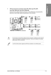
ASUS RAMPAGE V EXTREME 1-39 These are not jumpers! I =C o. The CPU_FAN connector supports the CPU fan of the connector. cu 4-pin CHA_FAN1A-3A; 4-pin CHA_FAN1B-3B) Connect the fan ... CHA FAN PAIR CHA FAN PWR CHA FAN IN CHA FAN IN CHA FAN IN O CHA FAN PWM CHA FAN PWM CHA FAN PWM Eno RAMPAGE V EXTREME Fan connectors OCHA_FAN2A QCHA_FAN2B F77 F77 PIE% PIE% gcl Do not forget to connect the fan cables to black wire of each cable matches the...
ASUS RAMPAGE V EXTREME 1-39 These are not jumpers! I =C o. The CPU_FAN connector supports the CPU fan of the connector. cu 4-pin CHA_FAN1A-3A; 4-pin CHA_FAN1B-3B) Connect the fan ... CHA FAN PAIR CHA FAN PWR CHA FAN IN CHA FAN IN CHA FAN IN O CHA FAN PWM CHA FAN PWM CHA FAN PWM Eno RAMPAGE V EXTREME Fan connectors OCHA_FAN2A QCHA_FAN2B F77 F77 PIE% PIE% gcl Do not forget to connect the fan cables to black wire of each cable matches the...

User Guide
Page 59
...that supports Intel's Thunderbolt a Technology, allowing you to connect up to six Thunderbolt-enabled devices and a CU DisplayPort-enabled display in a daisy-chain configuration. ASUS RAMPAGE V EXTREME 1-41 M.2 connector The M.2 (Socket 3) with M Key supports type 2260 (22 mm x 60 mm), 2280 (22 mm x 80 mm), and ...22110 (22 mm x 110 mm) PCIe interface storage devices. 2E M.2(SOCKET3) 11111111111111111 1 IzQ RAMPAGE V EXTREME M.2(SOCKET3) The PCIE_X8_4 slot shares bandwidth with M.2 x4. U CI= 'Nur J TB_HEADER H -7177 21111 Izo ID() LE 1=10. 11 EE =t === mmozd...
...that supports Intel's Thunderbolt a Technology, allowing you to connect up to six Thunderbolt-enabled devices and a CU DisplayPort-enabled display in a daisy-chain configuration. ASUS RAMPAGE V EXTREME 1-41 M.2 connector The M.2 (Socket 3) with M Key supports type 2260 (22 mm x 60 mm), 2280 (22 mm x 80 mm), and ...22110 (22 mm x 110 mm) PCIe interface storage devices. 2E M.2(SOCKET3) 11111111111111111 1 IzQ RAMPAGE V EXTREME M.2(SOCKET3) The PCIE_X8_4 slot shares bandwidth with M.2 x4. U CI= 'Nur J TB_HEADER H -7177 21111 Izo ID() LE 1=10. 11 EE =t === mmozd...


