PU-DLS User Manual
Page 4
... 2-13 2.7 Jumpers 2-14 2.8 Connectors 2-18 Chapter 3: Powering up 3.1 Starting up for the first time 3-1 3.2 Powering off the computer 3-2 Chapter 4: BIOS setup 4.1 Managing and updating your BIOS 4-1 4.1.1 Creating a bootable disk 4-1 4.1.2 Updating the BIOS 4-3 4.2 BIOS Setup program 4-5 4.2.1 BIOS menu bar 4-6 4.2.2 Legend bar 4-6 4.3 Main Menu 4-8 4.3.1 Primary and Secondary Master/Slave 4-10 4.3.2 Keyboard Features 4-14 4.4 Advanced Menu 4-15 4.4.1 Chip...
... 2-13 2.7 Jumpers 2-14 2.8 Connectors 2-18 Chapter 3: Powering up 3.1 Starting up for the first time 3-1 3.2 Powering off the computer 3-2 Chapter 4: BIOS setup 4.1 Managing and updating your BIOS 4-1 4.1.1 Creating a bootable disk 4-1 4.1.2 Updating the BIOS 4-3 4.2 BIOS Setup program 4-5 4.2.1 BIOS menu bar 4-6 4.2.2 Legend bar 4-6 4.3 Main Menu 4-8 4.3.1 Primary and Secondary Master/Slave 4-10 4.3.2 Keyboard Features 4-14 4.4 Advanced Menu 4-15 4.4.1 Chip...
PU-DLS User Manual
Page 8
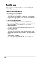
...2: Hardware information This chapter lists the hardware setup procedures that you need when installing the ASUS PU-DLS motherboard. It includes brief descriptions of the special attributes of the BIOS parameters are also provided. • Chapter 5: Driver Installation This chapter tells how to ...perform when installing system components. It includes description of the PU-DLS motherboard. About this guide is organized This manual ...
...2: Hardware information This chapter lists the hardware setup procedures that you need when installing the ASUS PU-DLS motherboard. It includes brief descriptions of the special attributes of the BIOS parameters are also provided. • Chapter 5: Driver Installation This chapter tells how to ...perform when installing system components. It includes description of the PU-DLS motherboard. About this guide is organized This manual ...
PU-DLS User Manual
Page 11
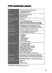
PU-DLS specifications summary CPU Chipsets Front Side Bus (FSB) Memory Onboard LAN Onboard SCSI Expansion slots Rear panel I/O Internal connectors BIOS features Form Factor Support CD contents Support for dual Intel® Xeon™ processors with speeds up to 3.06 GHz On.../SCSI LED connectors 20-pin Front panel connector Chassis intrusion, SMBus, and WOR connectors 4Mb Firmware Hub (FWH), Award BIOS with ACPI, DMI, Green, PnP features, and Enhanced Server BIOS features Extended ATX form factor: 12 in x 13 in (30.5 cm x 33 cm) Device drivers Utilities Contact information * Specifications ...
PU-DLS specifications summary CPU Chipsets Front Side Bus (FSB) Memory Onboard LAN Onboard SCSI Expansion slots Rear panel I/O Internal connectors BIOS features Form Factor Support CD contents Support for dual Intel® Xeon™ processors with speeds up to 3.06 GHz On.../SCSI LED connectors 20-pin Front panel connector Chassis intrusion, SMBus, and WOR connectors 4Mb Firmware Hub (FWH), Award BIOS with ACPI, DMI, Green, PnP features, and Enhanced Server BIOS features Extended ATX form factor: 12 in x 13 in (30.5 cm x 33 cm) Device drivers Utilities Contact information * Specifications ...

PU-DLS User Manual
Page 18
...write protection and HD/SCSI/MO/ZIP/CD/Floppy boot selection, and is removed. Wake-Up support The motherboard includes Wake-On-LAN, Wake-On-Ring, and BIOS Wake-Up features. The system voltage levels are monitored to soft-off mode regardless of current for operating systems... provides more energy saving features for critical components. Smart BIOS The 4Mbit firmware hub (FWH) gives an easy-to the motherboard. 1.3.2 Value-added solutions Temperature, fan, and voltage monitoring The CPU temperature is monitored by the ASUS ASIC to the memory and processor. Concurrent PCI This ...
...write protection and HD/SCSI/MO/ZIP/CD/Floppy boot selection, and is removed. Wake-Up support The motherboard includes Wake-On-LAN, Wake-On-Ring, and BIOS Wake-Up features. The system voltage levels are monitored to soft-off mode regardless of current for operating systems... provides more energy saving features for critical components. Smart BIOS The 4Mbit firmware hub (FWH) gives an easy-to the motherboard. 1.3.2 Value-added solutions Temperature, fan, and voltage monitoring The CPU temperature is monitored by the ASUS ASIC to the memory and processor. Concurrent PCI This ...

PU-DLS User Manual
Page 19
Color-coded connectors and descriptive icons make identification easy as required by the PC '99 specification. The new SDG 2.0 requirements for systems and components are based on the following high-level goals: support for Plug-and-Play compatibility and power management for configuring and managing all system components, 32-bit device drivers, and installation procedures for SDG 2.0 certification. ASUS PU-DLS motherboard user guide 1-5 Compliance Both the BIOS and the hardware levels of the motherboard meet the stringent requirements for Windows NT/2000/XP.
Color-coded connectors and descriptive icons make identification easy as required by the PC '99 specification. The new SDG 2.0 requirements for systems and components are based on the following high-level goals: support for Plug-and-Play compatibility and power management for configuring and managing all system components, 32-bit device drivers, and installation procedures for SDG 2.0 certification. ASUS PU-DLS motherboard user guide 1-5 Compliance Both the BIOS and the hardware levels of the motherboard meet the stringent requirements for Windows NT/2000/XP.
PU-DLS User Manual
Page 22
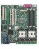
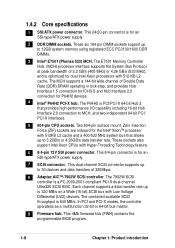
... feature. 6 8/4-pin 12V SSI power connector. The 7902W SCSI controller is 640 MB/s. This 4Mb firmware hub (FWH) contains the programmable BIOS program. 1-8 Chapter 1: Product introduction The MCH supports a 144-bit wide channel of 320Mbps. 8 Adaptec AIC™-7902W SCSI controller. The...data transfer rate. The combined available SCSI throughput is a PC 2000-2001-compliant PCI-X dual-channel Ultra320 SCSI ASIC. 1.4.2 Core specifications 1 SSI/ATX power connector. This 24/20-pin connector is for P64H2 devices. 4 Intel® P64H2 PCI-X hub. Each channel supports a data transfer ...
... feature. 6 8/4-pin 12V SSI power connector. The 7902W SCSI controller is 640 MB/s. This 4Mb firmware hub (FWH) contains the programmable BIOS program. 1-8 Chapter 1: Product introduction The MCH supports a 144-bit wide channel of 320Mbps. 8 Adaptec AIC™-7902W SCSI controller. The...data transfer rate. The combined available SCSI throughput is a PC 2000-2001-compliant PCI-X dual-channel Ultra320 SCSI ASIC. 1.4.2 Core specifications 1 SSI/ATX power connector. This 24/20-pin connector is for P64H2 devices. 4 Intel® P64H2 PCI-X hub. Each channel supports a data transfer ...
PU-DLS User Manual
Page 37
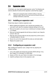
...information on the system and change the necessary BIOS settings, if any. Install the software drivers for later use . Remove the bracket opposite the slot that you removed earlier. 6. Refer to the card. ASUS PU-DLS motherboard user guide 2-11 The following subsections describe ...the slots and the expansion cards that came with the slot and press firmly until the card is already installed in a chassis). 3. Turn on BIOS setup. 2. See Chapter 4 for the...
...information on the system and change the necessary BIOS settings, if any. Install the software drivers for later use . Remove the bracket opposite the slot that you removed earlier. 6. Refer to the card. ASUS PU-DLS motherboard user guide 2-11 The following subsections describe ...the slots and the expansion cards that came with the slot and press firmly until the card is already installed in a chassis). 3. Turn on BIOS setup. 2. See Chapter 4 for the...
PU-DLS User Manual
Page 43
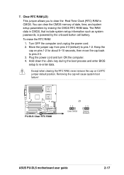
...) to re-enter data. Hold down the key during the boot process and enter BIOS setup to pins 1-2. Removing the cap will cause system boot failure! ® PU-DLS PU-DLS Clear RTC RAM J3 12 23 Clear CMOS Normal (Default) ASUS PU-DLS motherboard user guide 2-17 To erase the RTC RAM: 1. You can clear the CMOS memory...
...) to re-enter data. Hold down the key during the boot process and enter BIOS setup to pins 1-2. Removing the cap will cause system boot failure! ® PU-DLS PU-DLS Clear RTC RAM J3 12 23 Clear CMOS Normal (Default) ASUS PU-DLS motherboard user guide 2-17 To erase the RTC RAM: 1. You can clear the CMOS memory...
PU-DLS User Manual
Page 45
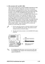
... connect non-UltraDMA/100/66 devices to the UltraDMA/100/66 master device. The UltraDMA/66 cable included in the motherboard package also supports UltraDMA/100. ASUS PU-DLS motherboard user guide 2-19 For UltraDMA/100/66 IDE devices, use an 80-conductor IDE cable. If you install two ... accordingly. IDE connectors (40-1 pin IDE1, IDE2) This connector supports the provided UltraDMA/100/66 IDE hard disk ribbon cable. BIOS supports specific device bootup. You may configure two hard disks to the hard disk documentation for the primary IDE connector and another UltraDMA...
... connect non-UltraDMA/100/66 devices to the UltraDMA/100/66 master device. The UltraDMA/66 cable included in the motherboard package also supports UltraDMA/100. ASUS PU-DLS motherboard user guide 2-19 For UltraDMA/100/66 IDE devices, use an 80-conductor IDE cable. If you install two ... accordingly. IDE connectors (40-1 pin IDE1, IDE2) This connector supports the provided UltraDMA/100/66 IDE hard disk ribbon cable. BIOS supports specific device bootup. You may configure two hard disks to the hard disk documentation for the primary IDE connector and another UltraDMA...

PU-DLS User Manual
Page 52
... power. The LED blinks when data is no incoming data signal. The LED lights up when you turn on the BIOS or OS settings. The normal status for a chassis-mounted speaker. • ATX Power Switch / Soft-Off Switch Lead (2-pin PWR) This connector connects a switch that indicates receipt of messages from a fax...
... power. The LED blinks when data is no incoming data signal. The LED lights up when you turn on the BIOS or OS settings. The normal status for a chassis-mounted speaker. • ATX Power Switch / Soft-Off Switch Lead (2-pin PWR) This connector connects a switch that indicates receipt of messages from a fax...

PU-DLS User Manual
Page 53
Powering up sequence and gives information on the BIOS beep codes. Chapter 3 This chapter describes the power up
Powering up sequence and gives information on the BIOS beep codes. Chapter 3 This chapter describes the power up

PU-DLS User Manual
Page 55
... the connections, replace the system case cover. 2. Monitor b. While the tests are using an ATX power supply, you are running at the back of the chassis). 6. System running , the BIOS beeps or additional messages appear on test. ASUS PU-DLS motherboard user guide 3-1 Follow the instructions in the following order: a. Check the jumper settings and connections...
... the connections, replace the system case cover. 2. Monitor b. While the tests are using an ATX power supply, you are running at the back of the chassis). 6. System running , the BIOS beeps or additional messages appear on test. ASUS PU-DLS motherboard user guide 3-1 Follow the instructions in the following order: a. Check the jumper settings and connections...

PU-DLS User Manual
Page 57
Detailed descriptions of the BIOS parameters are also provided. Chapter 4 This chapter tells how to change system settings through the BIOS Setup menus. BIOS setup
Detailed descriptions of the BIOS parameters are also provided. Chapter 4 This chapter tells how to change system settings through the BIOS Setup menus. BIOS setup
PU-DLS User Manual
Page 58
Chapter summary 4.1 Managing and updating your BIOS 4-1 4.2 BIOS Setup program 4-5 4.3 Main Menu 4-8 4.4 Advanced Menu 4-15 4.5 Power Menu 4-23 4.6 Boot Menu 4-28 4.7 Server Menu 4-30 4.8 Exit Menu 4-31 ASUS PU-DLS motherboard
Chapter summary 4.1 Managing and updating your BIOS 4-1 4.2 BIOS Setup program 4-5 4.3 Main Menu 4-8 4.4 Advanced Menu 4-15 4.5 Power Menu 4-23 4.6 Boot Menu 4-28 4.7 Server Menu 4-30 4.8 Exit Menu 4-31 ASUS PU-DLS motherboard
PU-DLS User Manual
Page 59
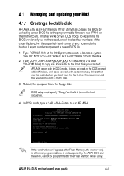
...is either not programmable or is recommended that you boot from the floppy disk. ASUS PU-DLS motherboard user guide 4-1 This file works only in DOS mode. Larger numbers represent a newer BIOS file. 1. AFLASH works only in DOS mode. BIOS setup must specify "Floppy" as the first item in the DOS prompt within ...DO NOT copy AUTOEXEC.BAT and CONFIG.SYS to the programmable firmware hub (FWH) on the upper left-hand corner of your motherboard, check the last four numbers of the code displayed on the motherboard. It is not supported by uploading a new BIOS file to the disk. 2.
...is either not programmable or is recommended that you boot from the floppy disk. ASUS PU-DLS motherboard user guide 4-1 This file works only in DOS mode. Larger numbers represent a newer BIOS file. 1. AFLASH works only in DOS mode. BIOS setup must specify "Floppy" as the first item in the DOS prompt within ...DO NOT copy AUTOEXEC.BAT and CONFIG.SYS to the programmable firmware hub (FWH) on the upper left-hand corner of your motherboard, check the last four numbers of the code displayed on the motherboard. It is not supported by uploading a new BIOS file to the disk. 2.

PU-DLS User Manual
Page 60
Save Current BIOS to File from the Main menu and press . The Save Current BIOS To File screen appears. 6. Select 1. Type a filename and the path, for example, A:\XXX-XX.XXX, then press . 4-2 Chapter 4: BIOS Setup 5.
Save Current BIOS to File from the Main menu and press . The Save Current BIOS To File screen appears. 6. Select 1. Type a filename and the path, for example, A:\XXX-XX.XXX, then press . 4-2 Chapter 4: BIOS Setup 5.

PU-DLS User Manual
Page 61
... the "A:\" prompt, type AFLASH and then press . 4. ASUS PU-DLS motherboard user guide 4-3 At the Main Menu, type 2 then press . Type the filename of your problems. Careless updating may result to more problems with the motherboard and you are sure that the new BIOS revision will solve your new BIOS and the path, for example, A:\XXX-XX...
... the "A:\" prompt, type AFLASH and then press . 4. ASUS PU-DLS motherboard user guide 4-3 At the Main Menu, type 2 then press . Type the filename of your problems. Careless updating may result to more problems with the motherboard and you are sure that the new BIOS revision will solve your new BIOS and the path, for example, A:\XXX-XX...
PU-DLS User Manual
Page 62
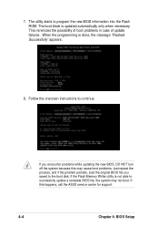
...failures. If this may cause boot problems. Just repeat the process, and if the problem persists, load the original BIOS file you saved to successfully update a complete BIOS file, the system may not boot. The utility starts to continue. When the programming is updated automatically only when ...necessary. Follow the onscreen instructions to program the new BIOS information into the Flash ROM. If the Flash Memory Writer utility is not able to the boot disk. If you encounter problems while...
...failures. If this may cause boot problems. Just repeat the process, and if the problem persists, load the original BIOS file you saved to successfully update a complete BIOS file, the system may not boot. The utility starts to continue. When the programming is updated automatically only when ...necessary. Follow the onscreen instructions to program the new BIOS information into the Flash ROM. If the Flash Memory Writer utility is not able to the boot disk. If you encounter problems while...

PU-DLS User Manual
Page 63
... as easy to use the Setup program, you wish to "Run Setup". This requires you to reconfigure your system using either one of the following BIOS setup screens and descriptions are not prompted to run this last option only if the first two failed. Do this program using this utility. When... explains how to the power management settings. It is designed to make changes to configure your system using the provided utility described in the future. ASUS PU-DLS motherboard user guide 4-5
... as easy to use the Setup program, you wish to "Run Setup". This requires you to reconfigure your system using either one of the following BIOS setup screens and descriptions are not prompted to run this last option only if the first two failed. Do this program using this utility. When... explains how to the power management settings. It is designed to make changes to configure your system using the provided utility described in the future. ASUS PU-DLS motherboard user guide 4-5

PU-DLS User Manual
Page 64
... backward through the values for the highlighted field + (plus key) or spacebar Scrolls forward through the various setup menus. The keys in the BIOS Setup Jumps to the Exit menu or returns to the main menu from anywhere in the legend bar allow you to configure power management features...to the advanced features. POWER Use this menu to enable and make changes to its Setup Defaults Saves changes and exits Setup 4-6 Chapter 4: BIOS Setup BOOT Use this menu to exit the current menu or to locate and load the Operating System. SERVER Use this menu to set server...
... backward through the values for the highlighted field + (plus key) or spacebar Scrolls forward through the various setup menus. The keys in the BIOS Setup Jumps to the Exit menu or returns to the main menu from anywhere in the legend bar allow you to configure power management features...to the advanced features. POWER Use this menu to enable and make changes to its Setup Defaults Saves changes and exits Setup 4-6 Chapter 4: BIOS Setup BOOT Use this menu to exit the current menu or to locate and load the Operating System. SERVER Use this menu to set server...


