

Users Manual English
Page 1
Motherboard PRIME H610M-K D4 ARGB
Motherboard PRIME H610M-K D4 ARGB
Users Manual English
Page 3
Contents Safety information...iv About this guide...v Package contents...vi PRIME H610M-K D4 ARGB specifications summary vii Chapter 1: Product Introduction 1.1 Before you proceed 1-1 1.2 Motherboard layout 1-2 1.3 CPU installation 1-8 1.4 DIMM installation 1-10 Chapter 2: BIOS Information 2.1 Knowing UEFI BIOS 2-1 2.2 ASUS EZ Flash 3 2-2 2.3 ASUS CrashFree BIOS 3 2-3 Appendix General Notices...A-1 Notices for non Wi-Fi model A-4 Warranty...A-6 ASUS contact information A-8 Service and Support A-8 Product Register...A-8 iii
Contents Safety information...iv About this guide...v Package contents...vi PRIME H610M-K D4 ARGB specifications summary vii Chapter 1: Product Introduction 1.1 Before you proceed 1-1 1.2 Motherboard layout 1-2 1.3 CPU installation 1-8 1.4 DIMM installation 1-10 Chapter 2: BIOS Information 2.1 Knowing UEFI BIOS 2-1 2.2 ASUS EZ Flash 3 2-2 2.3 ASUS CrashFree BIOS 3 2-3 Appendix General Notices...A-1 Notices for non Wi-Fi model A-4 Warranty...A-6 ASUS contact information A-8 Service and Support A-8 Product Register...A-8 iii
Users Manual English
Page 4
...; When adding or removing devices to or from the system, ensure that the power cables for the devices are unplugged before you encounter technical problems with the product, contact a qualified service technician or your retailer. • Your motherboard should only be used in any damage, contact your local power company. • If the power supply is set to the correct voltage in your retailer.
...; When adding or removing devices to or from the system, ensure that the power cables for the devices are unplugged before you encounter technical problems with the product, contact a qualified service technician or your retailer. • Your motherboard should only be used in any damage, contact your local power company. • If the power supply is set to the correct voltage in your retailer.

Users Manual English
Page 5
Where to find more information Refer to boot into the BIOS and upgrade BIOS using the EZ Flash Utility. Motherboard Installation Guide Please visit https://www.asus.com/support for more information on downloading and installing drivers and utilities for your dealer. v How this guide This user guide contains the information you need when installing and configuring the motherboard. Optional documentation Your product package may include optional documentation, such as warranty flyers, that may have...
Where to find more information Refer to boot into the BIOS and upgrade BIOS using the EZ Flash Utility. Motherboard Installation Guide Please visit https://www.asus.com/support for more information on downloading and installing drivers and utilities for your dealer. v How this guide This user guide contains the information you need when installing and configuring the motherboard. Optional documentation Your product package may include optional documentation, such as warranty flyers, that may have...
Users Manual English
Page 6
... trying to help you MUST follow to complete a task. IMPORTANT: Instructions that you perform certain tasks properly, take note of the following items. Motherboard Cables Miscellaneous Documentation 1 x PRIME H610M-K D4 ARGB motherboard 2 x SATA 6Gb/s cables 1 x I/O shield 1 x M.2 anchor 1 x Quick start guide • If any of the above are purchased separately and do not come bundled with your retailer. • Items not listed in this user guide.
... trying to help you MUST follow to complete a task. IMPORTANT: Instructions that you perform certain tasks properly, take note of the following items. Motherboard Cables Miscellaneous Documentation 1 x PRIME H610M-K D4 ARGB motherboard 2 x SATA 6Gb/s cables 1 x I/O shield 1 x M.2 anchor 1 x Quick start guide • If any of the above are purchased separately and do not come bundled with your retailer. • Items not listed in this user guide.
Users Manual English
Page 7
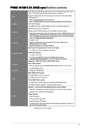
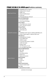
... CPU types. PRIME H610M-K D4 ARGB specifications summary CPU Chipset Memory Graphics Expansion Slots Storage Ethernet USB Audio Intel® Socket LGA1700 for Intel® Core™ 14th & 13th Gen Processors, Intel® Core™ 12th Gen, Pentium® Gold and Celeron® Processors* Supports Intel® Turbo Boost Technology 2.0 and Intel® Turbo Boost Max Technology 3.0** * Refer to www.asus.com for any updates. ** Supports 4K@60Hz as specified in the front panel is required to 24-Bit...
... CPU types. PRIME H610M-K D4 ARGB specifications summary CPU Chipset Memory Graphics Expansion Slots Storage Ethernet USB Audio Intel® Socket LGA1700 for Intel® Core™ 14th & 13th Gen Processors, Intel® Core™ 12th Gen, Pentium® Gold and Celeron® Processors* Supports Intel® Turbo Boost Technology 2.0 and Intel® Turbo Boost Max Technology 3.0** * Refer to www.asus.com for any updates. ** Supports 4K@60Hz as specified in the front panel is required to 24-Bit...
Users Manual English
Page 8
...LED Core - PRIME H610M-K D4 ARGB specifications summary Back Panel I/O Ports Internal I /O ASUS Q-Design - Q-DIMM - SafeSlot Core - Q-Slot ASUS Thermal Solution - DIGI+ VRM - Stainless-steel back I /O connectors Special Features 2 x USB 5Gbps ports (2 x Type-A) 4 x USB 2.0 ports (4 x Type-A) 1 x HDMI™ port 1 x Realtek 1Gb Ethernet port 3 x Audio jacks 1 x PS/2 keyboard/mouse combo port Fan and Cooling Related 1 x 4-pin CPU Fan header 1 x 4-pin Chassis Fan header Power Related 1 x 24-pin Main Power connector 1 x 8-pin +12V Power connector Storage Related 1 x M.2 slot (Key...
...LED Core - PRIME H610M-K D4 ARGB specifications summary Back Panel I/O Ports Internal I /O ASUS Q-Design - Q-DIMM - SafeSlot Core - Q-Slot ASUS Thermal Solution - DIGI+ VRM - Stainless-steel back I /O connectors Special Features 2 x USB 5Gbps ports (2 x Type-A) 4 x USB 2.0 ports (4 x Type-A) 1 x HDMI™ port 1 x Realtek 1Gb Ethernet port 3 x Audio jacks 1 x PS/2 keyboard/mouse combo port Fan and Cooling Related 1 x 4-pin CPU Fan header 1 x 4-pin Chassis Fan header Power Related 1 x 24-pin Main Power connector 1 x 8-pin +12V Power connector Storage Related 1 x M.2 slot (Key...
Users Manual English
Page 9
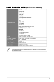
... Suite 3 - ASUS UEFI BIOS EZ Mode 128 Mb Flash ROM, UEFI AMI BIOS PRIME H610M-K D4 ARGB: PH610KA4.CAP WOL by PME, PXE Windows® 11 Windows® 10 64-bit micro-ATX Form Factor 9.2 inch x 8.0 inch (23.4 cm x 20.3 cm) Specifications are subject to the ASUS website for the latest specifications. ASUS CrashFree BIOS 3 - PRIME H610M-K D4 ARGB specifications summary Software Features BIOS BIOS CAP Filename Manageability Operating System Form Factor ASUS Exclusive Software Armoury Crate - Aura Sync - PC Cleaner ASUS CPU-Z Norton...
... Suite 3 - ASUS UEFI BIOS EZ Mode 128 Mb Flash ROM, UEFI AMI BIOS PRIME H610M-K D4 ARGB: PH610KA4.CAP WOL by PME, PXE Windows® 11 Windows® 10 64-bit micro-ATX Form Factor 9.2 inch x 8.0 inch (23.4 cm x 20.3 cm) Specifications are subject to the ASUS website for the latest specifications. ASUS CrashFree BIOS 3 - PRIME H610M-K D4 ARGB specifications summary Software Features BIOS BIOS CAP Filename Manageability Operating System Form Factor ASUS Exclusive Software Armoury Crate - Aura Sync - PC Cleaner ASUS CPU-Z Norton...

Users Manual English
Page 11
... before you install motherboard components or change any motherboard settings. • Unplug the power cord from the wall socket before touching any component. • Before handling components, use a grounded wrist strap or touch a safely grounded object or a metal object, such as the power supply case, to avoid damaging them . • Whenever you install or remove any component, place it on the location of the header/jumper/connector. •...
... before you install motherboard components or change any motherboard settings. • Unplug the power cord from the wall socket before touching any component. • Before handling components, use a grounded wrist strap or touch a safely grounded object or a metal object, such as the power supply case, to avoid damaging them . • Whenever you install or remove any component, place it on the location of the header/jumper/connector. •...

Users Manual English
Page 12
... TPM 128Mb BIOS SPEAKER F_PANEL 17 16 15 1.2.1 Layout contents 1. For more details, refer to DIMM installation. 1-2 Chapter 1: Product Introduction For more details, refer to CPU installation. 2. CPU socket The motherboard comes with Dual Inline Memory Modules (DIMM) slots designed for Intel® Core™ 14th & 13th Gen Processors, Intel® Core™ 12th Gen, Pentium® Gold and Celeron® Processors. DIMM slots The motherboard comes with...
... TPM 128Mb BIOS SPEAKER F_PANEL 17 16 15 1.2.1 Layout contents 1. For more details, refer to DIMM installation. 1-2 Chapter 1: Product Introduction For more details, refer to CPU installation. 2. CPU socket The motherboard comes with Dual Inline Memory Modules (DIMM) slots designed for Intel® Core™ 14th & 13th Gen Processors, Intel® Core™ 12th Gen, Pentium® Gold and Celeron® Processors. DIMM slots The motherboard comes with...

Users Manual English
Page 13
... Power connectors allow you to install an M.2 device such as optical disc drives and hard disk drives via SATA cables. 8. Find the proper orientation and push down firmly until the power supply plugs are designed to connect the 8-pin power plug. M.2 slot (Key M) The M.2 slot allows you to connect your motherboard to cool the system. USB 2.0 header The USB 2.0 header allows you to connect fans to a power supply. The USB 2.0 header provides data transfer speeds of up to connect a USB 5Gbps module for an additional USB 2.0 port...
... Power connectors allow you to install an M.2 device such as optical disc drives and hard disk drives via SATA cables. 8. Find the proper orientation and push down firmly until the power supply plugs are designed to connect the 8-pin power plug. M.2 slot (Key M) The M.2 slot allows you to connect your motherboard to cool the system. USB 2.0 header The USB 2.0 header allows you to connect fans to a power supply. The USB 2.0 header provides data transfer speeds of up to connect a USB 5Gbps module for an additional USB 2.0 port...

Users Manual English
Page 14
... RAM. Connect the COM port module cable to this board can handle a combined maximum of 3A (5V), and the addressable headers on this connector, then install the module to a slot opening on . 11. After clearing the CMOS, reinstall the button cell battery. 12. Failure to do not help, remove the onboard button cell battery and short the two pins again to connect individually addressable RGB WS2812B LED strips or WS2812B based LED strips. Short...
... RAM. Connect the COM port module cable to this board can handle a combined maximum of 3A (5V), and the addressable headers on this connector, then install the module to a slot opening on . 11. After clearing the CMOS, reinstall the button cell battery. 12. Failure to do not help, remove the onboard button cell battery and short the two pins again to connect individually addressable RGB WS2812B LED strips or WS2812B based LED strips. Short...
Users Manual English
Page 15
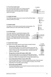
... GND F_PANEL +PWR_LED- PWR_BTN PIN 1 HDD_LED+ HDD_LED- Motherboard User Manual 1-5 RESET LED. Press the reset button to connect the Storage Device Activity +HDD_LED- 13. Front Panel Audio header The Front Panel Audio header is for the chassis-mounted system warning speaker. Connect one end of the front panel audio I /O module that supports HD Audio. F_AUDIO PIN 1 PORT1L PORT1R PORT2R SENSE_SEND PORT2L AGND NC SENSE1_RETUR SENSE2_RETUR 14. Speaker header The header is in sleep mode. SPEAKER PIN 1 +5V GND GND Speaker Out 16. A TPM...
... GND F_PANEL +PWR_LED- PWR_BTN PIN 1 HDD_LED+ HDD_LED- Motherboard User Manual 1-5 RESET LED. Press the reset button to connect the Storage Device Activity +HDD_LED- 13. Front Panel Audio header The Front Panel Audio header is for the chassis-mounted system warning speaker. Connect one end of the front panel audio I /O module that supports HD Audio. F_AUDIO PIN 1 PORT1L PORT1R PORT2R SENSE_SEND PORT2L AGND NC SENSE1_RETUR SENSE2_RETUR 14. Speaker header The header is in sleep mode. SPEAKER PIN 1 +5V GND GND Speaker Out 16. A TPM...

Users Manual English
Page 16
... Linked BLINKING Data activity Speed LED Status OFF ORANGE GREEN Description 10 Mbps connection 100 Mbps connection 1 Gbps connection ACT/LINK LED SPEED LED LAN port 1-6 Chapter 1: Product Introduction We strongly recommend that you connect your USB 5Gbps devices to ports with matching data transfer rate. USB 2.0 ports 5, 6, 7, 8 5. For example connecting your devices to USB 5Gbps ports for faster and better performance for LAN port LEDs, and audio port definitions. Audio jacks** 4. PS/2 Mouse/Keyboard combo port 2. HDMI™ port 6.
... Linked BLINKING Data activity Speed LED Status OFF ORANGE GREEN Description 10 Mbps connection 100 Mbps connection 1 Gbps connection ACT/LINK LED SPEED LED LAN port 1-6 Chapter 1: Product Introduction We strongly recommend that you connect your USB 5Gbps devices to ports with matching data transfer rate. USB 2.0 ports 5, 6, 7, 8 5. For example connecting your devices to USB 5Gbps ports for faster and better performance for LAN port LEDs, and audio port definitions. Audio jacks** 4. PS/2 Mouse/Keyboard combo port 2. HDMI™ port 6.

Users Manual English
Page 18
... user manual of the motherboard, ensure that the PnP cap is on installing the heatsink/AIO cooler. DO NOT install a CPU designed for LGA1700 socket only. Install a heatsink or AIO cooler after releasing it may cause the load lever to spring back and cause damage to prevent bending the connectors on the socket and damaging the CPU. • Ensure that all power cables are unplugged before installing...
... user manual of the motherboard, ensure that the PnP cap is on installing the heatsink/AIO cooler. DO NOT install a CPU designed for LGA1700 socket only. Install a heatsink or AIO cooler after releasing it may cause the load lever to spring back and cause damage to prevent bending the connectors on the socket and damaging the CPU. • Ensure that all power cables are unplugged before installing...

Users Manual English
Page 20
... the default state, some memory modules for the dual-channel configuration. For an optimum compatibility, we recommend that you install memory modules of the DDR4 DIMM sockets. The system maps the total size of accessing information from a memory module. Recommended memory configurations DIMM_A DIMM_B DIMM_A DIMM_B • You may operate at a lower frequency than the vendor-marked value. • For system stability, use a more efficient memory cooling...
... the default state, some memory modules for the dual-channel configuration. For an optimum compatibility, we recommend that you install memory modules of the DDR4 DIMM sockets. The system maps the total size of accessing information from a memory module. Recommended memory configurations DIMM_A DIMM_B DIMM_A DIMM_B • You may operate at a lower frequency than the vendor-marked value. • For system stability, use a more efficient memory cooling...
Users Manual English
Page 23
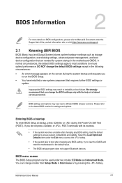
... boot failure. Please refer to the default value. • The BIOS setup program does not support Bluetooth devices. BIOS menu screen The BIOS Setup program can change the BIOS settings only with its routines. • If the system becomes unstable after changing any BIOS setting, load the default settings to ensure optimal performance. In normal circumstances, the default BIOS settings apply to most conditions to ensure system compatibility and stability. If you to different BIOS release versions. Motherboard User Manual 2-1 BIOS settings...
... boot failure. Please refer to the default value. • The BIOS setup program does not support Bluetooth devices. BIOS menu screen The BIOS Setup program can change the BIOS settings only with its routines. • If the system becomes unstable after changing any BIOS setting, load the default settings to ensure optimal performance. In normal circumstances, the default BIOS settings apply to most conditions to ensure system compatibility and stability. If you to different BIOS release versions. Motherboard User Manual 2-1 BIOS settings...
Users Manual English
Page 24
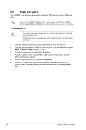
... to load the BIOS default settings to prevent system boot failure! 1. To update the BIOS: • This function can support devices such as a USB flash disk with FAT 32/16 format and single partition only. • DO NOT shut down or reset the system while updating the BIOS to ensure system compatibility and stability. Press the Up/Down arrow keys to find the BIOS file, and then press to the USB port...
... to load the BIOS default settings to prevent system boot failure! 1. To update the BIOS: • This function can support devices such as a USB flash disk with FAT 32/16 format and single partition only. • DO NOT shut down or reset the system while updating the BIOS to ensure system compatibility and stability. Press the Up/Down arrow keys to find the BIOS file, and then press to the USB port...
Users Manual English
Page 25
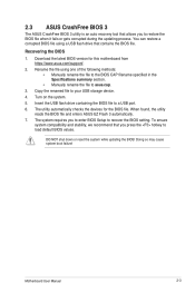
... BIOS 1. Rename the file using a USB flash drive that contains the BIOS file. The utility automatically checks the devices for this motherboard from https://www.asus.com/support/. 2. DO NOT shut down or reset the system while updating the BIOS! Doing so may cause system boot failure! When found, the utility reads the BIOS file and enters ASUS EZ Flash 3 automatically. 7. 2.3 ASUS CrashFree BIOS 3 The ASUS CrashFree BIOS 3 utility is an auto recovery tool that allows you to enter BIOS Setup to recover the BIOS setting. Turn...
... BIOS 1. Rename the file using a USB flash drive that contains the BIOS file. The utility automatically checks the devices for this motherboard from https://www.asus.com/support/. 2. DO NOT shut down or reset the system while updating the BIOS! Doing so may cause system boot failure! When found, the utility reads the BIOS file and enters ASUS EZ Flash 3 automatically. 7. 2.3 ASUS CrashFree BIOS 3 The ASUS CrashFree BIOS 3 utility is an auto recovery tool that allows you to enter BIOS Setup to recover the BIOS setting. Turn...

Users Manual English
Page 27
...: Asus Computer International Address: 48720 Kato Rd., Fremont, CA 94538, USA Phone / Fax No: (510)739-3777 / (510)608-4555 This device complies with the instructions, may not cause harmful interference, and (2) this product have been designed and verified for the use accessories for other products to prevent the risk of electric shock or fire. Motherboard User Manual...
...: Asus Computer International Address: 48720 Kato Rd., Fremont, CA 94538, USA Phone / Fax No: (510)739-3777 / (510)608-4555 This device complies with the instructions, may not cause harmful interference, and (2) this product have been designed and verified for the use accessories for other products to prevent the risk of electric shock or fire. Motherboard User Manual...


