
User Guide
Page 3
... About this guide vii PCH-DR specifications summary ix Chapter 1: Product introduction 1.1 Welcome 1-1 1.2 Package contents 1-1 1.3 Special features 1-2 Chapter 2: Hardware information 2.1 Before you proceed 2-1 2.2 Motherboard installation 2-2 2.2.1 Placement direction 2-2 2.2.2 Screw holes 2-2 2.2.3 Motherboard layout 2-3 2.2.4 Layout Contents 2-4 2.3 Central Processing Unit (CPU 2-6 2.3.1 Overview 2-6 2.3.2 Installing the CPU 2-6 2.3.3 Installing the CPU heatsink and fan 2-8 2.4 System memory 2-13 2.4.1 Overview 2-13 2.4.2 Memory configurations 2-13 2.4.3 Installing...
... About this guide vii PCH-DR specifications summary ix Chapter 1: Product introduction 1.1 Welcome 1-1 1.2 Package contents 1-1 1.3 Special features 1-2 Chapter 2: Hardware information 2.1 Before you proceed 2-1 2.2 Motherboard installation 2-2 2.2.1 Placement direction 2-2 2.2.2 Screw holes 2-2 2.2.3 Motherboard layout 2-3 2.2.4 Layout Contents 2-4 2.3 Central Processing Unit (CPU 2-6 2.3.1 Overview 2-6 2.3.2 Installing the CPU 2-6 2.3.3 Installing the CPU heatsink and fan 2-8 2.4 System memory 2-13 2.4.1 Overview 2-13 2.4.2 Memory configurations 2-13 2.4.3 Installing...
User Guide
Page 4
...13 4.3.3 Secondary IDE Master 4-13 4.3.4 Secondary IDE Slave 4-13 4.3.5 Third IDE Master 4-14 4.3.6 Fourth IDE Master 4-14 4.4 Advanced menu 4-15 4.4.1 CPU Configuration 4-15 4.4.2 Memory Configuration 4-16 4.4.3 Chipset 4-18 4.4.4 Onboard Device 4-20 4.4.5 PCIPnP 4-25 4.4.6 USB Configuration 4-27 4.5 Power menu 4-28 4.5.1 APM Configuration 4-28 4.5.2 Hardware Monitor 4-31 4.6... Boot Priority 4-34 4.6.3 Removable Device Priority 4-34 4.6.4 Boot Settings Configuration 4-35 4.6.5 Security 4-37 4.7 Exit menu 4-38 Appendix: Reference information A.1 PCH-DR block diagram A-1 iv
...13 4.3.3 Secondary IDE Master 4-13 4.3.4 Secondary IDE Slave 4-13 4.3.5 Third IDE Master 4-14 4.3.6 Fourth IDE Master 4-14 4.4 Advanced menu 4-15 4.4.1 CPU Configuration 4-15 4.4.2 Memory Configuration 4-16 4.4.3 Chipset 4-18 4.4.4 Onboard Device 4-20 4.4.5 PCIPnP 4-25 4.4.6 USB Configuration 4-27 4.5 Power menu 4-28 4.5.1 APM Configuration 4-28 4.5.2 Hardware Monitor 4-31 4.6... Boot Priority 4-34 4.6.3 Removable Device Priority 4-34 4.6.4 Boot Settings Configuration 4-35 4.6.5 Security 4-37 4.7 Exit menu 4-38 Appendix: Reference information A.1 PCH-DR block diagram A-1 iv

User Guide
Page 9
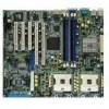
PCH-DR specifications summary CPU Chipset Front Side Bus (FSB) Memory Expansion slots Storage LAN Rear panel I/O Internal connectors Dual 604-pin sockets for Intel® Xeon™ Processors 3.2GHz with Hyper-Threding Technology On-die 1MB/512KB L2 cache North bridge: Intel® E7210 Memory Controller Hub (MCH) South ...bridge: Intel® 6300ESB I/O Controller Hub (ICH) 533/400 MHz Dual-channel memory architecture 4 x 184-pin DDR DIMM sockets for up to 4GB memory Supports PC2700/PC2100 unbuffered ECC or non-ECC DDR DIMMs 2 x 3.3V/64-bit/66MHz PCI-X 3 x 5V/32-bit/33MHz...
PCH-DR specifications summary CPU Chipset Front Side Bus (FSB) Memory Expansion slots Storage LAN Rear panel I/O Internal connectors Dual 604-pin sockets for Intel® Xeon™ Processors 3.2GHz with Hyper-Threding Technology On-die 1MB/512KB L2 cache North bridge: Intel® E7210 Memory Controller Hub (MCH) South ...bridge: Intel® 6300ESB I/O Controller Hub (ICH) 533/400 MHz Dual-channel memory architecture 4 x 184-pin DDR DIMM sockets for up to 4GB memory Supports PC2700/PC2100 unbuffered ECC or non-ECC DDR DIMMs 2 x 3.3V/64-bit/66MHz PCI-X 3 x 5V/32-bit/33MHz...
User Guide
Page 13
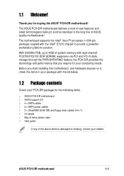
... for buying the ASUS® PCH-DR motherboard! With 533MHz FSB, up to provide a powerful workstation platform solution. Before you start installing the motherboard, and hardware devices on it another standout in 604-pin package coupled with the Intel® E7210 chipset to 4GB of system memory with the list below. 1.2 Package contents Check your retailer. ASUS PCH-DR motherboard 1-1
... for buying the ASUS® PCH-DR motherboard! With 533MHz FSB, up to provide a powerful workstation platform solution. Before you start installing the motherboard, and hardware devices on it another standout in 604-pin package coupled with the Intel® E7210 chipset to 4GB of system memory with the list below. 1.2 Package contents Check your retailer. ASUS PCH-DR motherboard 1-1

User Guide
Page 14
...graphics, multimedia, and Internet applications. Dual-channel DDR333 memory support Employing the dual-channel DDR memory architecture, the motherboard provides a solution that allows up to 3.2GHz core frequencies. Multi-RAID solution The motherboard has the Promise® PDC20378 controller to support ... pin count, reduced voltage requirement, and up to 4GB of system memory using Serial ATA/150 hard disks. The motherboard supports up to 150MB/s data transfer rate. USB 2.0 technology The motherboard implements the Universal Serial Bus (USB) 2.0 specification, dramatically increasing the...
...graphics, multimedia, and Internet applications. Dual-channel DDR333 memory support Employing the dual-channel DDR memory architecture, the motherboard provides a solution that allows up to 3.2GHz core frequencies. Multi-RAID solution The motherboard has the Promise® PDC20378 controller to support ... pin count, reduced voltage requirement, and up to 4GB of system memory using Serial ATA/150 hard disks. The motherboard supports up to 150MB/s data transfer rate. USB 2.0 technology The motherboard implements the Universal Serial Bus (USB) 2.0 specification, dramatically increasing the...

User Guide
Page 15
ASUS PCH-DR motherboard 1-3 Instead of connecting to the PCI bus, the controller connects to support 32-bit LAN through the Communication Streaming Architecture (CSA). The Intel® 82541GI Gigabit Ethernet controller is also onboard to the dedicated CSA bus on Motherboard (LOM) applications through the PCI bus. Gigabit LAN solution The Intel® 82547GI Gigabit Ethernet controller allows full-duplex Gigabit performance on LAN on the Memory Controller Hub (MCH) thus reducing the PCI bottlenecks by freeing the PCI bus for other I/O operations.
ASUS PCH-DR motherboard 1-3 Instead of connecting to the PCI bus, the controller connects to support 32-bit LAN through the Communication Streaming Architecture (CSA). The Intel® 82541GI Gigabit Ethernet controller is also onboard to the dedicated CSA bus on Motherboard (LOM) applications through the PCI bus. Gigabit LAN solution The Intel® 82547GI Gigabit Ethernet controller allows full-duplex Gigabit performance on LAN on the Memory Controller Hub (MCH) thus reducing the PCI bottlenecks by freeing the PCI bus for other I/O operations.

User Guide
Page 18
Chapter summary 2.1 Before you proceed 2-1 2.2 Motherboard installation 2-2 2.3 Central Processing Unit (CPU 2-6 2.4 System memory 2-13 2.5 Expansion slots 2-16 2.6 Jumpers 2-19 2.7 Connectors 2-24 ASUS PCH-DR motherboard
Chapter summary 2.1 Before you proceed 2-1 2.2 Motherboard installation 2-2 2.3 Central Processing Unit (CPU 2-6 2.4 System memory 2-13 2.5 Expansion slots 2-16 2.6 Jumpers 2-19 2.7 Connectors 2-24 ASUS PCH-DR motherboard

User Guide
Page 27
Position the heatsink on top of the CPU, having its holes with the four holes on the motherboard and the standoffs on the retention mechanism. 2. Heatsink angled side ASUS PCH-DR motherboard 2-9 Heatsink retention mechanism 3. Secure the retention mechanism with cut corners) facing the memory sockets. Make sure that the heatsink base fits completely on the thermal plate. Place the heatsink retention mechanism over the CPU socket, matching its angled side (with the thermal plate using four screws. 4.
Position the heatsink on top of the CPU, having its holes with the four holes on the motherboard and the standoffs on the retention mechanism. 2. Heatsink angled side ASUS PCH-DR motherboard 2-9 Heatsink retention mechanism 3. Secure the retention mechanism with cut corners) facing the memory sockets. Make sure that the heatsink base fits completely on the thermal plate. Place the heatsink retention mechanism over the CPU socket, matching its angled side (with the thermal plate using four screws. 4.
User Guide
Page 31
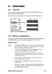
... latency. Use any three sockets will function in singlechannel mode. 6. For optimum compatibility, it is recommended that the memory frequency matches the CPU FSB (Front Side Bus). ASUS PCH-DR motherboard 2-13 Make sure that you obtain memory modules from the same vendor. 4. In dual-channel configurations, install only identical (the same type and size) DDR...
... latency. Use any three sockets will function in singlechannel mode. 6. For optimum compatibility, it is recommended that the memory frequency matches the CPU FSB (Front Side Bus). ASUS PCH-DR motherboard 2-13 Make sure that you obtain memory modules from the same vendor. 4. In dual-channel configurations, install only identical (the same type and size) DDR...

User Guide
Page 32
... DDR_A2 and DDR_B2 (black sockets) Table 2 Memory frequency/CPU FSB synchronization CPU FSB 533 MHz 400 MHz DDR DIMM Type PC2700/PC2100 PC2100 Memory Frequency 333/266 MHz 266 MHz Obtain DDR DIMMs only from ASUS qualified vendors for the latest QVL. 2-14 ...Chapter 2: Hardware information Visit the ASUS website (www.asus.com) for better system performance. Populated - (2) - Populated - Table 1 Recommended memory configurations Mode Single-...
... DDR_A2 and DDR_B2 (black sockets) Table 2 Memory frequency/CPU FSB synchronization CPU FSB 533 MHz 400 MHz DDR DIMM Type PC2700/PC2100 PC2100 Memory Frequency 333/266 MHz 266 MHz Obtain DDR DIMMs only from ASUS qualified vendors for the latest QVL. 2-14 ...Chapter 2: Hardware information Visit the ASUS website (www.asus.com) for better system performance. Populated - (2) - Populated - Table 1 Recommended memory configurations Mode Single-...
User Guide
Page 55
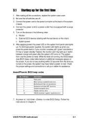
... not operational Keyboard controller BAT test error General exception error Display memory error CMOS shutdown register read/write error 7. External SCSI devices (starting with a surge protector. 5. If your retailer for the first time 1. ASUS PCH-DR motherboard 3-1 For SSI-type power supplies, the system LED lights up . At power on, hold down to a power outlet...
... not operational Keyboard controller BAT test error General exception error Display memory error CMOS shutdown register read/write error 7. External SCSI devices (starting with a surge protector. 5. If your retailer for the first time 1. ASUS PCH-DR motherboard 3-1 For SSI-type power supplies, the system LED lights up . At power on, hold down to a power outlet...

User Guide
Page 65
... desired item is highlighted. ASUS PCH-DR motherboard 4-7 4.2.1 BIOS menu screen Menu bar Menu items General help Time (hh:mm:ss) Date (mm:dd:yy) Legacy Diskette A Floppy 3 Mode Support Primary IDE Master Primary IDE Slave Secondary IDE Master Secondary IDE Slave Third IDE Master Fourth IDE Master Base Memory Extended Memory Total Memory 11: 10 : 30 Fri...
... desired item is highlighted. ASUS PCH-DR motherboard 4-7 4.2.1 BIOS menu screen Menu bar Menu items General help Time (hh:mm:ss) Date (mm:dd:yy) Legacy Diskette A Floppy 3 Mode Support Primary IDE Master Primary IDE Slave Secondary IDE Master Secondary IDE Slave Third IDE Master Fourth IDE Master Base Memory Extended Memory Total Memory 11: 10 : 30 Fri...
User Guide
Page 67
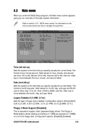
... the key to 59). Configuration options: [Disabled] [Enabled] ASUS PCH-DR motherboard 4-9 Time (hh:mm:ss) Date (mm:dd:yy) Legacy Diskette A Floppy 3 Mode Support Primary IDE Master Primary IDE Slave Secondary IDE Master Secondary IDE Slave Third IDE Master Fourth IDE Master Base Memory Extended Memory Total Memory 11: 10 : 30 Fri, Apr 30 2004 [1.44M, 3.5 in...
... the key to 59). Configuration options: [Disabled] [Enabled] ASUS PCH-DR motherboard 4-9 Time (hh:mm:ss) Date (mm:dd:yy) Legacy Diskette A Floppy 3 Mode Support Primary IDE Master Primary IDE Slave Secondary IDE Master Secondary IDE Slave Third IDE Master Fourth IDE Master Base Memory Extended Memory Total Memory 11: 10 : 30 Fri, Apr 30 2004 [1.44M, 3.5 in...

User Guide
Page 68
... too new. If automatic detection is not yet detected. In these cases, select [Manual] to detect the presence of a IDE drive. Base/Extended/Total Memory [xxxK] The base memory, extended memory, and total memory values are not user-configurable. 4.3.1 Primary IDE Master Primary Master Auto-Detection Primary IDE Master Access Mode Capacity Cylinder Head Precomp Landing...
... too new. If automatic detection is not yet detected. In these cases, select [Manual] to detect the presence of a IDE drive. Base/Extended/Total Memory [xxxK] The base memory, extended memory, and total memory values are not user-configurable. 4.3.1 Primary IDE Master Primary Master Auto-Detection Primary IDE Master Access Mode Capacity Cylinder Head Precomp Landing...
User Guide
Page 73
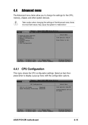
... the CPU, memory, chipset, and other system devices. CPU Configuration CPU L1 & L2 Cache [Enabled] Hyper-Threading Technology [Enabled] Select Menu Item Specific Help Disable/Enable CPU L1/ L2 cache. 4.4 Advanced menu The Advanced menu items allow you to set. 4.4.1 CPU Configuration This menu shows the CPU configuration settings. ASUS PCH-DR motherboard 4-15 Take...
... the CPU, memory, chipset, and other system devices. CPU Configuration CPU L1 & L2 Cache [Enabled] Hyper-Threading Technology [Enabled] Select Menu Item Specific Help Disable/Enable CPU L1/ L2 cache. 4.4 Advanced menu The Advanced menu items allow you to set. 4.4.1 CPU Configuration This menu shows the CPU configuration settings. ASUS PCH-DR motherboard 4-15 Take...

User Guide
Page 74
... Hyper-Threading Technolody [Enabled] Allows you to CAS# Delay DRAM RAS# Precharge Memory Parity Check [Auto] [By SPD] 2.5 7 3 3 Enabled Select Menu Item Specific Help Set DRAM Frequency. Memory Configuration DRAM Frequency Memory Timing Selectable Cache Latency Time Active to Precharge Delay DRAM RAS# to enable or... disable the CPU Hyper-Threading Technology feature. Select [Manual] to allow setting the succeeding memory items to display a pop-up menu with the configuration options. Select an item then press Enter to optimal timings. Set ...
... Hyper-Threading Technolody [Enabled] Allows you to CAS# Delay DRAM RAS# Precharge Memory Parity Check [Auto] [By SPD] 2.5 7 3 3 Enabled Select Menu Item Specific Help Set DRAM Frequency. Memory Configuration DRAM Frequency Memory Timing Selectable Cache Latency Time Active to Precharge Delay DRAM RAS# to enable or... disable the CPU Hyper-Threading Technology feature. Select [Manual] to allow setting the succeeding memory items to display a pop-up menu with the configuration options. Select an item then press Enter to optimal timings. Set ...

User Guide
Page 75
...clocks used for DRAM parameters. Configuration options: [2] [2.5] [3] Active to the DDR SDRAM. Configuration options: [4] [3] [2] Memory Parity Check [Enabled] Allows memory parity checking option (ECC). Configuration options: [Disabled] [Enabled] ASUS PCH-DR motherboard 4-17 Configuration options: [8] [7] [6] [5] DRAM RAS# to [Manual]. CAS Latency Time [2.5] This item sets the ... Delay, DRAM RAS# to CAS# Delay, and DRAM RAS# Precharge are configurable only when the Memory Timing Selectable item is set to CAS# Delay [3] Controls the latency between the DRAM read / write command.
...clocks used for DRAM parameters. Configuration options: [2] [2.5] [3] Active to the DDR SDRAM. Configuration options: [4] [3] [2] Memory Parity Check [Enabled] Allows memory parity checking option (ECC). Configuration options: [Disabled] [Enabled] ASUS PCH-DR motherboard 4-17 Configuration options: [8] [7] [6] [5] DRAM RAS# to [Manual]. CAS Latency Time [2.5] This item sets the ... Delay, DRAM RAS# to CAS# Delay, and DRAM RAS# Precharge are configurable only when the Memory Timing Selectable item is set to CAS# Delay [3] Controls the latency between the DRAM read / write command.


