
User Guide
Page 4
Safeguards Contents Chapter 3: Powering up 3.1 Starting up for the first time 3-1 3.2 Vocal POST Messages 3-2 3.3 Powering off the computer 3-4 Chapter 4: BIOS setup 4.1 Managing and updating your BIOS 4-1 4.1.1 Creating a bootable floppy disk 4-1 4.1.2 Updating the BIOS 4-2 4.2 BIOS Setup program 4-3 4.2.1 BIOS menu screen 4-4 4.2.2 Menu bar 4-4 4.2.3 Navigation keys 4-5 4.2.4 General help 4-5 4.2.5 Sub-menu 4-5 4.2.6 Scroll bar 4-5 4.2.7 Pop-up window 4-5 4.3 Main menu 4-6 4.3.1 Primary and...
Safeguards Contents Chapter 3: Powering up 3.1 Starting up for the first time 3-1 3.2 Vocal POST Messages 3-2 3.3 Powering off the computer 3-4 Chapter 4: BIOS setup 4.1 Managing and updating your BIOS 4-1 4.1.1 Creating a bootable floppy disk 4-1 4.1.2 Updating the BIOS 4-2 4.2 BIOS Setup program 4-3 4.2.1 BIOS menu screen 4-4 4.2.2 Menu bar 4-4 4.2.3 Navigation keys 4-5 4.2.4 General help 4-5 4.2.5 Sub-menu 4-5 4.2.6 Scroll bar 4-5 4.2.7 Pop-up window 4-5 4.3 Main menu 4-6 4.3.1 Primary and...

User Guide
Page 5
...™ utility 5-12 5.4.3 Creating a RAID 0 array (Performance 5-13 5.4.4 Creating a RAID 1 array (Security 5-14 5.4.5 Other FastBuild Utility Commands 5-16 5.5 Intel® RAID for Serial ATA 5-18 5.5.1 BIOS configuration 5-18 5.5.2 Installing Serial ATA hard disks 5-19 5.5.3 Creating, Deleting, and Resetting RAID Sets ...... 5-19 5.5.4 Creating a RAID Volume 5-20 5.5.5 Deleting a RAID Volume 5-21 5.5.6 Resetting a RAID...
...™ utility 5-12 5.4.3 Creating a RAID 0 array (Performance 5-13 5.4.4 Creating a RAID 1 array (Security 5-14 5.4.5 Other FastBuild Utility Commands 5-16 5.5 Intel® RAID for Serial ATA 5-18 5.5.1 BIOS configuration 5-18 5.5.2 Installing Serial ATA hard disks 5-19 5.5.3 Creating, Deleting, and Resetting RAID Sets ...... 5-19 5.5.4 Creating a RAID Volume 5-20 5.5.5 Deleting a RAID Volume 5-21 5.5.6 Resetting a RAID...

User Guide
Page 8
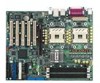
...1: Product introduction This chapter describes the features of the PC-DL Deluxe motherboard. How this guide This user guide contains the information you have to perform when installing system components. It includes description of the BIOS parameters are also provided. • Chapter 5: Driver ...installation This chapter tells how to change system settings through the BIOS Setup menus. Detailed description of the jumpers and connectors on the ...
...1: Product introduction This chapter describes the features of the PC-DL Deluxe motherboard. How this guide This user guide contains the information you have to perform when installing system components. It includes description of the BIOS parameters are also provided. • Chapter 5: Driver ...installation This chapter tells how to change system settings through the BIOS Setup menus. Detailed description of the jumpers and connectors on the ...
User Guide
Page 12
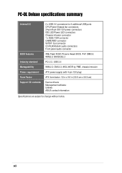
...12V plug) ATX form factor: 12 in x 9.6 in (30.5 cm x 24.5 cm) Device drivers Management software Utilities ASUS contact information Specifications are subject to change without notice. PC-DL Deluxe specifications summary Internal I/O BIOS features Industry standard Manageability Power requirement Form Factor Support CD contents 2 x USB 2.0 connectors for 4 additional USB ports CPU/... IEEE 1394 connector GAME/MIDI connector S/PDIF Out connector CD/AUX/Modem audio connectors Front panel audio connector 4Mb Flash ROM, Phoenix Award BIOS, PnP, DMI2.0, WfM2.0, SM BIOS2.3 PCI 2.3, USB 2.0 WfM 2.0.
...12V plug) ATX form factor: 12 in x 9.6 in (30.5 cm x 24.5 cm) Device drivers Management software Utilities ASUS contact information Specifications are subject to change without notice. PC-DL Deluxe specifications summary Internal I/O BIOS features Industry standard Manageability Power requirement Form Factor Support CD contents 2 x USB 2.0 connectors for 4 additional USB ports CPU/... IEEE 1394 connector GAME/MIDI connector S/PDIF Out connector CD/AUX/Modem audio connectors Front panel audio connector 4Mb Flash ROM, Phoenix Award BIOS, PnP, DMI2.0, WfM2.0, SM BIOS2.3 PCI 2.3, USB 2.0 WfM 2.0.
User Guide
Page 17
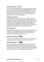
... during the Power-On Self-Tests (POST) informing you to customize the voice messages in different languages. ASUS PC-DL Deluxe motherboard 1-3 See section "4.4.1 Advanced Chipset Features" to set the BIOS items for other I/O operations. 6-channel audio feature The SoundMAX-class ADI AD1985 AC '97 audio CODEC supports...on LAN on the installed CPU and DRAM) to enhance system performance while still maintaining system stability. ASUS Q-Fan technology The ASUS Q-Fan technology smartly adjusts the fan speeds according to the system loading to ensure quiet, cool, and efficient operation.
... during the Power-On Self-Tests (POST) informing you to customize the voice messages in different languages. ASUS PC-DL Deluxe motherboard 1-3 See section "4.4.1 Advanced Chipset Features" to set the BIOS items for other I/O operations. 6-channel audio feature The SoundMAX-class ADI AD1985 AC '97 audio CODEC supports...on LAN on the installed CPU and DRAM) to enhance system performance while still maintaining system stability. ASUS Q-Fan technology The ASUS Q-Fan technology smartly adjusts the fan speeds according to the system loading to ensure quiet, cool, and efficient operation.
User Guide
Page 19
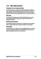
... detection The motherboard supports chassis intrusion monitoring through a user-friendly interface. ASUS PC-DL Deluxe motherboard 1-5 Connect to the Internet then to the ASUS FTP site nearest you to obtain the latest BIOS version for your motherboard. ASUS Update This utility allows you to update the motherboard BIOS through the Winbond ASIC. 1.3.2 Value-added solutions Temperature, fan, and...
... detection The motherboard supports chassis intrusion monitoring through a user-friendly interface. ASUS PC-DL Deluxe motherboard 1-5 Connect to the Internet then to the ASUS FTP site nearest you to obtain the latest BIOS version for your motherboard. ASUS Update This utility allows you to update the motherboard BIOS through the Winbond ASIC. 1.3.2 Value-added solutions Temperature, fan, and...
User Guide
Page 22
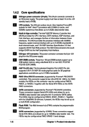
... memory interface with 512KB L2 cache, and 533MHz system bus that supports 8X/4X Fast Write protocol. This 4Mb firmware hub (FWH) contains the programmable BIOS program. 10 SATA connectors (supported by Promise® PDC20378 controller). Two 604-pin surface mount, Zero Insertion Force (ZIF) sockets for up as RAID 0/RAID...
... memory interface with 512KB L2 cache, and 533MHz system bus that supports 8X/4X Fast Write protocol. This 4Mb firmware hub (FWH) contains the programmable BIOS program. 10 SATA connectors (supported by Promise® PDC20378 controller). Two 604-pin surface mount, Zero Insertion Force (ZIF) sockets for up as RAID 0/RAID...
User Guide
Page 40
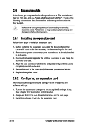
...card. 2. Turn on the next page. 3. Refer to the card. Remove the system unit cover (if your motherboard is completely seated on BIOS setup. 2. Before installing the expansion card, read the documentation that they support. Assign an IRQ to the tables on the system and change ...the necessary BIOS settings, if any. The motherboard has five PCI slots and one Accelerated Graphics Port (AGP) Pro slot. 2.6 Expansion slots In the future...
...card. 2. Turn on the next page. 3. Refer to the card. Remove the system unit cover (if your motherboard is completely seated on BIOS setup. 2. Before installing the expansion card, read the documentation that they support. Assign an IRQ to the tables on the system and change ...the necessary BIOS settings, if any. The motherboard has five PCI slots and one Accelerated Graphics Port (AGP) Pro slot. 2.6 Expansion slots In the future...

User Guide
Page 46
...ON the computer. 4. Shut down the key during the boot process and enter BIOS setup to overclocking. Clear RTC RAM (CLRTC1) This jumper allows you to default values. 2-20 Chapter 2: Hardware information To erase the RTC RAM: 1. PC-DL PC-DL Clear RTC RAM CLRTC1 12 23 Normal (Default) Clear CMOS You do not... powered by erasing the CMOS RTC RAM data. Turn OFF the computer and unplug the power cord. 2. Hold down and reboot the system so BIOS can clear the CMOS memory of date, time, and system setup parameters by the onboard button cell battery. The RAM data in CMOS. Keep ...
...ON the computer. 4. Shut down the key during the boot process and enter BIOS setup to overclocking. Clear RTC RAM (CLRTC1) This jumper allows you to default values. 2-20 Chapter 2: Hardware information To erase the RTC RAM: 1. PC-DL PC-DL Clear RTC RAM CLRTC1 12 23 Normal (Default) Clear CMOS You do not... powered by erasing the CMOS RTC RAM data. Turn OFF the computer and unplug the power cord. 2. Hold down and reboot the system so BIOS can clear the CMOS memory of date, time, and system setup parameters by the onboard button cell battery. The RAM data in CMOS. Keep ...
User Guide
Page 48
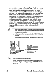
... the secondary IDE connector. 1. This prevents incorrect orientation when you must configure the second drive as a slave device by setting its jumper accordingly. PC-DL PC-DL IDE Connectors SEC_IDE1 PIN 1 PRI_IDE1 PIN 1 NOTE: Orient the red markings (usually zigzag) on how to the secondary IDE connector. MS-DOS,...The hole near the blue connector on the UltraDMA cable connector. one for the primary IDE connector and another for the jumper settings. BIOS supports specific device bootup. Important note when using legacy OS Refer to page 2-21 on the IDE ribbon cable to the UltraDMA/...
... the secondary IDE connector. 1. This prevents incorrect orientation when you must configure the second drive as a slave device by setting its jumper accordingly. PC-DL PC-DL IDE Connectors SEC_IDE1 PIN 1 PRI_IDE1 PIN 1 NOTE: Orient the red markings (usually zigzag) on how to the secondary IDE connector. MS-DOS,...The hole near the blue connector on the UltraDMA cable connector. one for the primary IDE connector and another for the jumper settings. BIOS supports specific device bootup. Important note when using legacy OS Refer to page 2-21 on the IDE ribbon cable to the UltraDMA/...
User Guide
Page 50
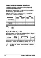
... supported by Intel ICH5R specifications. Windows 98/Me/NT4.0 Configuration A Configuration B Configuration C Legend: - Required Serial ATA settings in BIOS Refer to the following table for details on the related BIOS items. 2-24 Chapter 2: Hardware information Master - S-ATA Port 0 Port 1 (1 device) (1 device) - - Master - ... Primary Master or Slave Primary or Sec. ICH5R supports a maximum of the above Parallel ATA and Serial ATA device configurations. BIOS item On-Chip Serial ATA Serial ATA Port0 Mode Serial ATA Port1 Mode Windows 2000/XP Windows 98/Me/NT4.0 A B...
... supported by Intel ICH5R specifications. Windows 98/Me/NT4.0 Configuration A Configuration B Configuration C Legend: - Required Serial ATA settings in BIOS Refer to the following table for details on the related BIOS items. 2-24 Chapter 2: Hardware information Master - S-ATA Port 0 Port 1 (1 device) (1 device) - - Master - ... Primary Master or Slave Primary or Sec. ICH5R supports a maximum of the above Parallel ATA and Serial ATA device configurations. BIOS item On-Chip Serial ATA Serial ATA Port0 Mode Serial ATA Port1 Mode Windows 2000/XP Windows 98/Me/NT4.0 A B...
User Guide
Page 51
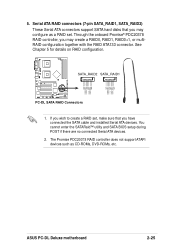
...174; PDC20378 RAID controller, you may configure as CD-ROMs, DVD-ROMs, etc. You cannot enter the SATARaid™ utility and SATA BIOS setup during POST if there are no connected Serial ATA devices. 2. Serial ATA RAID connectors (7-pin SATA_RAID1, SATA_RAID2) These Serial ATA connectors... together with the RAID ATA133 connector. GND RSATA_TXP2 RSATA_TXN2 GND RSATA_RXP2 RSATA_RXN2 GND GND RSATA_TXP1 RSATA_TXN1 GND RSATA_RXP1 RSATA_RXN1 GND ASUS PC-DL Deluxe motherboard 2-25 5. SATA_RAID2 SATA_RAID1 PC-DL PC-DL SATA RAID Connectors 1. See Chapter 5 for details on RAID configuration.
...174; PDC20378 RAID controller, you may configure as CD-ROMs, DVD-ROMs, etc. You cannot enter the SATARaid™ utility and SATA BIOS setup during POST if there are no connected Serial ATA devices. 2. Serial ATA RAID connectors (7-pin SATA_RAID1, SATA_RAID2) These Serial ATA connectors... together with the RAID ATA133 connector. GND RSATA_TXP2 RSATA_TXN2 GND RSATA_RXP2 RSATA_RXN2 GND GND RSATA_TXP1 RSATA_TXN1 GND RSATA_RXP1 RSATA_RXN1 GND ASUS PC-DL Deluxe motherboard 2-25 5. SATA_RAID2 SATA_RAID1 PC-DL PC-DL SATA RAID Connectors 1. See Chapter 5 for details on RAID configuration.

User Guide
Page 59
Pressing the power switch turns the system between ON and SLEEP, or ON and SOFT OFF, depending on the BIOS or OS settings. ASUS PC-DL Deluxe motherboard 2-33 • System Warning Speaker Lead (4-pin SPKR) This 4-pin connector connects to the case-mounted speaker and allows you to hear system beeps ...
Pressing the power switch turns the system between ON and SLEEP, or ON and SOFT OFF, depending on the BIOS or OS settings. ASUS PC-DL Deluxe motherboard 2-33 • System Warning Speaker Lead (4-pin SPKR) This 4-pin connector connects to the case-mounted speaker and allows you to hear system beeps ...

User Guide
Page 61
Powering up sequence and gives information on the BIOS beep codes. Chapter 3 This chapter describes the power up
Powering up sequence and gives information on the BIOS beep codes. Chapter 3 This chapter describes the power up

User Guide
Page 63
...Starting up for assistance. For ATX power supplies, the system LED lights up . Award/Phoenix BIOS beep codes No. At power on the screen. ASUS PC-DL Deluxe motherboard 3-1 After making all switches are running, the BIOS beeps (see anything within 30 seconds from the time you press the ATX power switch. After...the chain) c. Be sure that is equipped with the last device on . While the tests are off. 3. If you do not see BIOS beep codes table below) or additional messages appear on , hold down to a power outlet that all the connections, replace the system case cover....
...Starting up for assistance. For ATX power supplies, the system LED lights up . Award/Phoenix BIOS beep codes No. At power on the screen. ASUS PC-DL Deluxe motherboard 3-1 After making all switches are running, the BIOS beeps (see anything within 30 seconds from the time you press the ATX power switch. After...the chain) c. Be sure that is equipped with the last device on . While the tests are off. 3. If you do not see BIOS beep codes table below) or additional messages appear on , hold down to a power outlet that all the connections, replace the system case cover....
User Guide
Page 64
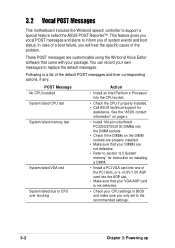
...BIOS and make sure you only set to inform you will hear the specific cause of system events and boot status. In case of a boot failure, you of the problem. This feature gives you vocal POST messages and alerts to the recommended settings. 3-2 Chapter 3: Powering up See the "ASUS...list of the PCI slots, or a +0.8V/1.5V AGP card into the CPU socket. • Check the CPU if properly installed. • Call ASUS technical support for instruction on the DIMM sockets are properly installed. • Make sure that your DIMMs are customizable using the Winbond Voice Editor software...
...BIOS and make sure you only set to inform you will hear the specific cause of system events and boot status. In case of a boot failure, you of the problem. This feature gives you vocal POST messages and alerts to the recommended settings. 3-2 Chapter 3: Powering up See the "ASUS...list of the PCI slots, or a +0.8V/1.5V AGP card into the CPU socket. • Check the CPU if properly installed. • Call ASUS technical support for instruction on the DIMM sockets are properly installed. • Make sure that your DIMMs are customizable using the Winbond Voice Editor software...
User Guide
Page 66
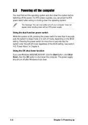
..., you use Windows 98SE/ME/2000/XP, click the Start button, click Shut Down, then the OK button to soft-off mode, depending on the BIOS setting. The message "You can press the ATX power switch after Windows shuts down. 3-4 Chapter 3: Powering up Using the dual function power switch While the... OS shut down function If you can now safely turn off after exiting or shutting down the system before switching off mode regardless of the BIOS setting. Pressing the power switch for less than 4 seconds lets the system enter the soft-off the power. See section "4.5 Power Menu" in Chapter...
..., you use Windows 98SE/ME/2000/XP, click the Start button, click Shut Down, then the OK button to soft-off mode, depending on the BIOS setting. The message "You can press the ATX power switch after Windows shuts down. 3-4 Chapter 3: Powering up Using the dual function power switch While the... OS shut down function If you can now safely turn off after exiting or shutting down the system before switching off mode regardless of the BIOS setting. Pressing the power switch for less than 4 seconds lets the system enter the soft-off the power. See section "4.5 Power Menu" in Chapter...

User Guide
Page 67
BIOS setup Chapter 4 This chapter tells how to change system settings through the BIOS Setup menus. Detailed descriptions of the BIOS parameters are also provided.
BIOS setup Chapter 4 This chapter tells how to change system settings through the BIOS Setup menus. Detailed descriptions of the BIOS parameters are also provided.

User Guide
Page 68
Chapter summary 4.1 Managing and updating your BIOS 4-1 4.2 BIOS Setup program 4-3 4.3 Main menu 4-6 4.4 Advanced menu 4-11 4.5 Power menu 4-23 4.6 Boot menu 4-27 4.7 Exit menu 4-31 ASUS PC-DL Deluxe motherboard
Chapter summary 4.1 Managing and updating your BIOS 4-1 4.2 BIOS Setup program 4-3 4.3 Main menu 4-6 4.4 Advanced menu 4-11 4.5 Power menu 4-23 4.6 Boot menu 4-27 4.7 Exit menu 4-31 ASUS PC-DL Deluxe motherboard
User Guide
Page 69
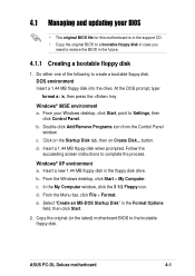
...Panel window. c. Follow the succeeding screen instructions to create a bootable floppy disk. b. Copy the original (or the latest) motherboard BIOS to restore the BIOS in the future. 4.1.1 Creating a bootable floppy disk 1. Click on the Startup Disk tab, then on Create Disk... Insert a... BIOS • The original BIOS file for this motherboard is in the support CD. • Copy the original BIOS to a bootable floppy disk in case you need to the bootable floppy disk. From the Windows desktop, click Start > My Computer. d. Windows® XP environment a. ASUS PC-DL Deluxe ...
...Panel window. c. Follow the succeeding screen instructions to create a bootable floppy disk. b. Copy the original (or the latest) motherboard BIOS to restore the BIOS in the future. 4.1.1 Creating a bootable floppy disk 1. Click on the Startup Disk tab, then on Create Disk... Insert a... BIOS • The original BIOS file for this motherboard is in the support CD. • Copy the original BIOS to a bootable floppy disk in case you need to the bootable floppy disk. From the Windows desktop, click Start > My Computer. d. Windows® XP environment a. ASUS PC-DL Deluxe ...
