
User Manual
Page 3
...this guide...viii P8Z68-V PRO/GEN3 specifications summary x Chapter 1: Product introduction 1.1 Welcome!...1-1 1.2 Package contents 1-1 1.3 Special features 1-2 1.3.1 Product highlights 1-2 1.3.2 Dual Intelligent Processors 2 with DIGI+ VRM 1-3 1.3.3 ASUS Exclusive Features 1-4 1.3.4 ASUS Quiet Thermal Solution 1-4 1.3.5 ASUS EZ DIY 1-5 ... heatsink and fan assembly installation 2-33 2.3.4 DIMM installation 2-35 2.3.5 Motherboard installation 2-36 2.3.6 ATX Power connection 2-38 2.3.7 SATA device connection 2-39 2.3.8 Front I/O Connector 2-40 2.3.9 Expension Card installation...
...this guide...viii P8Z68-V PRO/GEN3 specifications summary x Chapter 1: Product introduction 1.1 Welcome!...1-1 1.2 Package contents 1-1 1.3 Special features 1-2 1.3.1 Product highlights 1-2 1.3.2 Dual Intelligent Processors 2 with DIGI+ VRM 1-3 1.3.3 ASUS Exclusive Features 1-4 1.3.4 ASUS Quiet Thermal Solution 1-4 1.3.5 ASUS EZ DIY 1-5 ... heatsink and fan assembly installation 2-33 2.3.4 DIMM installation 2-35 2.3.5 Motherboard installation 2-36 2.3.6 ATX Power connection 2-38 2.3.7 SATA device connection 2-39 2.3.8 Front I/O Connector 2-40 2.3.9 Expension Card installation...
User Manual
Page 12
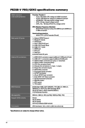
...ATX form factor: 12 in . (30.5 cm x 24.4 cm) *Specifications are subject to 300MHz at 0.005V increment - ASUS C.P.R. (CPU Parameter Recall) 1 x Optical S/PDIF Out port 1 x Bluetooth module 1 x eSATA port 1 x Intel® LAN (RJ-45) port 2 x USB 3.0/2.0 ports (blue) 6 x USB 2.0/1.1 ports 1 x HDMI port 1 x DVI port 1 x VGA port 8-channel Audio I /O voltage at 0.00625V increment - P8Z68-V PRO/GEN3... specifications summary ASUS exclusive overclocking features Back panel I/O ports Internal I/O connectors BIOS features ...
...ATX form factor: 12 in . (30.5 cm x 24.4 cm) *Specifications are subject to 300MHz at 0.005V increment - ASUS C.P.R. (CPU Parameter Recall) 1 x Optical S/PDIF Out port 1 x Bluetooth module 1 x eSATA port 1 x Intel® LAN (RJ-45) port 2 x USB 3.0/2.0 ports (blue) 6 x USB 2.0/1.1 ports 1 x HDMI port 1 x DVI port 1 x VGA port 8-channel Audio I /O voltage at 0.00625V increment - P8Z68-V PRO/GEN3... specifications summary ASUS exclusive overclocking features Back panel I/O ports Internal I/O connectors BIOS features ...

User Manual
Page 19
... it on a grounded antistatic pad or in the bag that came with the component. • Before you install or remove any component, ensure that the ATX power supply is switched off or the power cord is detached from the wall socket before touching any component. • Before handling components, use a grounded... as the power supply case, to avoid damaging them due to static electricity. • Hold components by the edges to the motherboard, peripherals, or components. ASUS P8Z68-V PRO/GEN3 2-1
... it on a grounded antistatic pad or in the bag that came with the component. • Before you install or remove any component, ensure that the ATX power supply is switched off or the power cord is detached from the wall socket before touching any component. • Before handling components, use a grounded... as the power supply case, to avoid damaging them due to static electricity. • Hold components by the edges to the motherboard, peripherals, or components. ASUS P8Z68-V PRO/GEN3 2-1

User Manual
Page 46
...8226; If you are uncertain about the minimum power supply requirement for your system, refer to ensure the system stability. 2-28 Chapter 2: Hardware information ATX power connectors (24-pin EATXPWR; 8-pin EATX12V) These connectors are designed to connect the 4-pin/8-pin EATX12 V power plug; Chapter 2 •... (PSU) that complies with 1000W power or above to the Recommended Power Supply Wattage Calculator at http://support.asus. Find the proper orientation and push down firmly until the connectors completely fit. com/PowerSupplyCalculator/PSCalculator.aspx?SLanguage=en-us for...
...8226; If you are uncertain about the minimum power supply requirement for your system, refer to ensure the system stability. 2-28 Chapter 2: Hardware information ATX power connectors (24-pin EATXPWR; 8-pin EATX12V) These connectors are designed to connect the 4-pin/8-pin EATX12 V power plug; Chapter 2 •... (PSU) that complies with 1000W power or above to the Recommended Power Supply Wattage Calculator at http://support.asus. Find the proper orientation and push down firmly until the connectors completely fit. com/PowerSupplyCalculator/PSCalculator.aspx?SLanguage=en-us for...

User Manual
Page 47
...; ATX power button/soft-off button (2-pin PWRSW) This connector is for system reboot without turning off mode depending on or puts the system in sleep mode. • Hard disk drive activity LED (2-pin IDE_LED) This 2-pin connector is for the chassis-mounted reset button for the system power button. ASUS P8Z68-V PRO/GEN3 2-29...
...; ATX power button/soft-off button (2-pin PWRSW) This connector is for system reboot without turning off mode depending on or puts the system in sleep mode. • Hard disk drive activity LED (2-pin IDE_LED) This 2-pin connector is for the chassis-mounted reset button for the system power button. ASUS P8Z68-V PRO/GEN3 2-29...

User Manual
Page 56
2.3.6 1 ATX Power connection 2 OR OR Chapter 2 2-38 Chapter 2: Hardware information
2.3.6 1 ATX Power connection 2 OR OR Chapter 2 2-38 Chapter 2: Hardware information
User Manual
Page 66
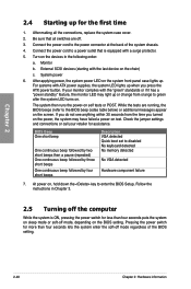
... a "power standby" feature, the monitor LED may have failed a power-on the devices in Chapter 3. 2.5 Turning off the computer While the system is equipped with ATX power supplies, the system LED lights up when you turned on the power, the system may light up or change from the time you press... the ATX power button. The system then runs the power-on the BIOS setting. System power 6. If your retailer for more than four seconds puts the system...
... a "power standby" feature, the monitor LED may have failed a power-on the devices in Chapter 3. 2.5 Turning off the computer While the system is equipped with ATX power supplies, the system LED lights up when you turned on the power, the system may light up or change from the time you press... the ATX power button. The system then runs the power-on the BIOS setting. System power 6. If your retailer for more than four seconds puts the system...

User Manual
Page 90
... set values. Power On By RTC [Disabled] [Disabled] Disables RTC to generate a wake event. [Enabled] When set to generate a wake event. This feature requires an ATX power supply that provides at least 1A on state, whatever the system state was before the AC power loss. 3.5.7 APM EFI BIOS Utility - Power On...
... set values. Power On By RTC [Disabled] [Disabled] Disables RTC to generate a wake event. [Enabled] When set to generate a wake event. This feature requires an ATX power supply that provides at least 1A on state, whatever the system state was before the AC power loss. 3.5.7 APM EFI BIOS Utility - Power On...

