
User Manual
Page 1
P8H67-M Motherboard
P8H67-M Motherboard

User Manual
Page 3
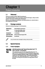
Contents Notices...vi Safety information vii About this guide vii P8H67-M specifications summary ix Chapter 1: Product introduction 1.1 Welcome 1-1 1.2 Package contents 1-1 1.3 Special features 1-1 1.3.1 Product highlights 1-1 1.3.2 Innovative ASUS features 1-3 1.4 Before you proceed 1-5 1.5 Motherboard overview 1-6 1.5.1 Placement direction 1-6 1.5.2 Screw holes 1-6 1.5.3 Motherboard layout 1-7 1.5.4 Layout contents 1-7 1.6 Central Processing Unit (CPU 1-8 1.6.1 Installing the CPU 1-8 1.6.2 Installing the CPU heatsink and fan 1-11 1.6.3 Uninstalling...
Contents Notices...vi Safety information vii About this guide vii P8H67-M specifications summary ix Chapter 1: Product introduction 1.1 Welcome 1-1 1.2 Package contents 1-1 1.3 Special features 1-1 1.3.1 Product highlights 1-1 1.3.2 Innovative ASUS features 1-3 1.4 Before you proceed 1-5 1.5 Motherboard overview 1-6 1.5.1 Placement direction 1-6 1.5.2 Screw holes 1-6 1.5.3 Motherboard layout 1-7 1.5.4 Layout contents 1-7 1.6 Central Processing Unit (CPU 1-8 1.6.1 Installing the CPU 1-8 1.6.2 Installing the CPU heatsink and fan 1-11 1.6.3 Uninstalling...
User Manual
Page 6
.... Operation is no guarantee that the product (electrical and electronic equipment) should not be placed in our products at ASUS REACH website at http://csr.asus.com/english/REACH.htm. Changes or modifications to enable proper reuse of Chemicals) regulatory framework, we published the chemical ...of Communications. vi Notices Federal Communications Commission Statement This device complies with Part 15 of the FCC Rules. DO NOT throw the motherboard in municipal waste. DO NOT throw the mercury-containing button cell battery in municipal waste. These limits are designed to Part ...
.... Operation is no guarantee that the product (electrical and electronic equipment) should not be placed in our products at ASUS REACH website at http://csr.asus.com/english/REACH.htm. Changes or modifications to enable proper reuse of Chemicals) regulatory framework, we published the chemical ...of Communications. vi Notices Federal Communications Commission Statement This device complies with Part 15 of the FCC Rules. DO NOT throw the motherboard in municipal waste. DO NOT throw the mercury-containing button cell battery in municipal waste. These limits are designed to Part ...

User Manual
Page 7
...before using an adapter or extension cord. How this guide This user guide contains the information you need when installing and configuring the motherboard. Contact a qualified service technician or your local power company. • If the power supply is set to the correct voltage ... ensure that the power cables for the devices are unplugged before the signal cables are also provided. Operation safety • Before installing the motherboard and adding devices on a stable surface. • If you are not damaged. vii Safety information Electrical safety • To prevent electric...
...before using an adapter or extension cord. How this guide This user guide contains the information you need when installing and configuring the motherboard. Contact a qualified service technician or your local power company. • If the power supply is set to the correct voltage ... ensure that the power cables for the devices are unplugged before the signal cables are also provided. Operation safety • Before installing the motherboard and adding devices on a stable surface. • If you are not damaged. vii Safety information Electrical safety • To prevent electric...
User Manual
Page 13
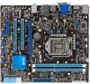
... Express 2.0 lanes. This provides great graphics performance. Before you for the following items. Motherboard Cables Accessories Application DVD Documentation ASUS P8H67-M motherboard 2 x Serial ATA 6.0Gb/s cables 1 x Ultra DMA 133/100 cable 1 x I/O shield ASUS motherboard support DVD User Manual If any of ASUS quality motherboards! ASUS P8H67-M 1-1 The motherboard delivers a host of new features and latest technologies, making it , check the items...
... Express 2.0 lanes. This provides great graphics performance. Before you for the following items. Motherboard Cables Accessories Application DVD Documentation ASUS P8H67-M motherboard 2 x Serial ATA 6.0Gb/s cables 1 x Ultra DMA 133/100 cable 1 x I/O shield ASUS motherboard support DVD User Manual If any of ASUS quality motherboards! ASUS P8H67-M 1-1 The motherboard delivers a host of new features and latest technologies, making it , check the items...
User Manual
Page 14
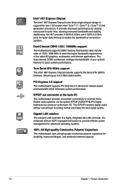
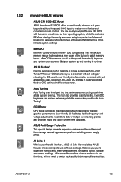
... interface, delivering up to provide efficient power management for advanced operating systems. 100% All High-quality Conductive Polymer Capacitors This motherboard uses all high-quality conductive polymer capacitors for durability, improved lifespan, and enhanced thermal capacity. 1-2 Chapter 1: Product introduction ...i7 / Core™ i5 / Core™ i3 2nd generation processors. S/PDIF out connector at the back I /O This motherboard provides convenient connectivity to meet the higher bandwidth requirements of your system memory to analog format and keeps the best signal quality....
... interface, delivering up to provide efficient power management for advanced operating systems. 100% All High-quality Conductive Polymer Capacitors This motherboard uses all high-quality conductive polymer capacitors for durability, improved lifespan, and enhanced thermal capacity. 1-2 Chapter 1: Product introduction ...i7 / Core™ i5 / Core™ i3 2nd generation processors. S/PDIF out connector at the back I /O This motherboard provides convenient connectivity to meet the higher bandwidth requirements of your system memory to analog format and keeps the best signal quality....
User Manual
Page 15
... profiles also provides rapid and stable system-level upgrades. ASUS Anti-Surge Protection This special design prevents expensive devices and the motherboard from damage caused by power surges from switching power supply (PSU). ASUS P8H67-M 1-3 You can achieve extreme yet stable overclocking results ...with just a few clicks away. ASUS TurboV Feel the adrenaline rush of the button...
... profiles also provides rapid and stable system-level upgrades. ASUS Anti-Surge Protection This special design prevents expensive devices and the motherboard from damage caused by power surges from switching power supply (PSU). ASUS P8H67-M 1-3 You can achieve extreme yet stable overclocking results ...with just a few clicks away. ASUS TurboV Feel the adrenaline rush of the button...

User Manual
Page 16
... hot airflows generated by the chipset. ASUS CrashFree BIOS 3 ASUS CrashFree BIOS 3 is a utility that offers users a noiseless PC environment. The beautifully curved fins not only upgrade the visual enjoyment for a more colorful and vivid image on your favorite photo into a 256-color boot logo for motherboard users, but also effectively cools down...
... hot airflows generated by the chipset. ASUS CrashFree BIOS 3 ASUS CrashFree BIOS 3 is a utility that offers users a noiseless PC environment. The beautifully curved fins not only upgrade the visual enjoyment for a more colorful and vivid image on your favorite photo into a 256-color boot logo for motherboard users, but also effectively cools down...

User Manual
Page 17
1.4 Before you proceed Take note of the following precautions before you install motherboard components or change any motherboard settings. • Unplug the power cord from the wall socket before touching any component. • Before handling components, use a grounded wrist strap or ... that the ATX power supply is switched off or the power cord is detached from the power supply. ASUS P8H67-M 1-5 Failure to do so may cause severe damage to avoid touching the ICs on them due to static electricity. • Hold components by the edges to the motherboard, peripherals, or components.
1.4 Before you proceed Take note of the following precautions before you install motherboard components or change any motherboard settings. • Unplug the power cord from the wall socket before touching any component. • Before handling components, use a grounded wrist strap or ... that the ATX power supply is switched off or the power cord is detached from the power supply. ASUS P8H67-M 1-5 Failure to do so may cause severe damage to avoid touching the ICs on them due to static electricity. • Hold components by the edges to the motherboard, peripherals, or components.
User Manual
Page 18
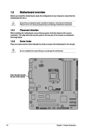
... to secure the motherboard to the chassis. Place this side towards the rear of the chassis as indicated in the image below. 1.5.2 Screw holes Place six screws into it into the chassis in the correct orientation. The edge with external ports goes to the rear part of the chassis P8H67-M 1-6 Chapter 1: Product... introduction Ensure that you unplug the power cord before installing or removing the motherboard.
... to secure the motherboard to the chassis. Place this side towards the rear of the chassis as indicated in the image below. 1.5.2 Screw holes Place six screws into it into the chassis in the correct orientation. The edge with external ports goes to the rear part of the chassis P8H67-M 1-6 Chapter 1: Product... introduction Ensure that you unplug the power cord before installing or removing the motherboard.

User Manual
Page 20
...released from incorrect CPU installation/removal, or misplacement/loss/incorrect removal of the motherboard, ensure that the PnP cap is shipment/transit-related. • Keep the cap after installing the motherboard. P8H67-M PRO P8H67-M CPU socket LGA1155 2. Locate the CPU socket on the socket and ... a CPU: 1. Contact your thumb (A), and then move it to the PnP cap/socket contacts/motherboard components. ASUS will process Return Merchandise Authorization (RMA) requests only if the motherboard comes with the cap on the LGA1155 socket. • The product warranty does not cover damage to...
...released from incorrect CPU installation/removal, or misplacement/loss/incorrect removal of the motherboard, ensure that the PnP cap is shipment/transit-related. • Keep the cap after installing the motherboard. P8H67-M PRO P8H67-M CPU socket LGA1155 2. Locate the CPU socket on the socket and ... a CPU: 1. Contact your thumb (A), and then move it to the PnP cap/socket contacts/motherboard components. ASUS will process Return Merchandise Authorization (RMA) requests only if the motherboard comes with the cap on the LGA1155 socket. • The product warranty does not cover damage to...

User Manual
Page 23
... the package includes the CPU fan and heatsink assembly. The illustration above is incompatible with the LGA775 and LGA1366 sockets in size and dimension. ASUS P8H67-M 1-11 To install the CPU heatsink and fan: A 1. Push down two fasteners at a time in a diagonal sequence to secure the .... If you purchased a separate CPU heatsink and fan assembly, ensure that you buy a CPU separately, ensure that you have installed the motherboard to the chassis before you install the CPU fan and heatsink assembly. 1.6.2 Installing the CPU heatsink and fan The Intel® LGA1155 processor...
... the package includes the CPU fan and heatsink assembly. The illustration above is incompatible with the LGA775 and LGA1366 sockets in size and dimension. ASUS P8H67-M 1-11 To install the CPU heatsink and fan: A 1. Push down two fasteners at a time in a diagonal sequence to secure the .... If you purchased a separate CPU heatsink and fan assembly, ensure that you buy a CPU separately, ensure that you have installed the motherboard to the chassis before you install the CPU fan and heatsink assembly. 1.6.2 Installing the CPU heatsink and fan The Intel® LGA1155 processor...
User Manual
Page 24
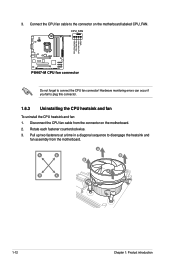
Hardware monitoring errors can occur if you fail to disengage the heatsink and fan assembly from the connector on the motherboard labeled CPU_FAN. Pull up two fasteners at a time in a diagonal sequence to plug this connector. 1.6.3 Uninstalling the CPU heatsink and fan To uninstall the CPU ...heatsink and fan: 1. Disconnect the CPU fan cable from the motherboard. Connect the CPU fan cable to connect the CPU fan connector! CPU_FAN CPU FAN PWM CPU FAN IN CPU FAN PWR GND...
Hardware monitoring errors can occur if you fail to disengage the heatsink and fan assembly from the connector on the motherboard labeled CPU_FAN. Pull up two fasteners at a time in a diagonal sequence to plug this connector. 1.6.3 Uninstalling the CPU heatsink and fan To uninstall the CPU ...heatsink and fan: 1. Disconnect the CPU fan cable from the motherboard. Connect the CPU fan cable to connect the CPU fan connector! CPU_FAN CPU FAN PWM CPU FAN IN CPU FAN PWR GND...

User Manual
Page 25
... correct orientation when reinstalling. 1.7 System memory 1.7.1 Overview The motherboard comes with less power consumption. The figure illustrates the location of the DDR3 DIMM sockets: DIMM_A1 DIMM_A2 DIMM_B1 DIMM_B2 P8H67-M Channel Channel A Channel B Sockets DIMM_A1 and DIMM_A2 DIMM_B1 and DIMM_B2 P8H67-M 240-pin DDR3 DIMM sockets ASUS P8H67-M 1-13 Rotate each fastener clockwise to prevent installation...
... correct orientation when reinstalling. 1.7 System memory 1.7.1 Overview The motherboard comes with less power consumption. The figure illustrates the location of the DDR3 DIMM sockets: DIMM_A1 DIMM_A2 DIMM_B1 DIMM_B2 P8H67-M Channel Channel A Channel B Sockets DIMM_A1 and DIMM_A2 DIMM_B1 and DIMM_B2 P8H67-M 240-pin DDR3 DIMM sockets ASUS P8H67-M 1-13 Rotate each fastener clockwise to prevent installation...

User Manual
Page 26
...memory frequency adjustment. • For system stability, use of memory, we recommend that you install 4GB or more on the motherboard. • This motherboard does not support DIMMs made up of 512Mb (64MB) chips or less. • The default memory operation frequency is ... configuration. For effective use a more efficient memory cooling system to support a full memory load (4 DIMMs) or overclocking condition. • ASUS exclusively provides hyper DIMM support function. • Hyper DIMM support is subject to the physical characteristics of the following: - Under the default...
...memory frequency adjustment. • For system stability, use of memory, we recommend that you install 4GB or more on the motherboard. • This motherboard does not support DIMMs made up of 512Mb (64MB) chips or less. • The default memory operation frequency is ... configuration. For effective use a more efficient memory cooling system to support a full memory load (4 DIMMs) or overclocking condition. • ASUS exclusively provides hyper DIMM support function. • Hyper DIMM support is subject to the physical characteristics of the following: - Under the default...

User Manual
Page 30
.... 3 Locked Retaining Clip 1.7.4 Removing a DIMM Follow these steps to unlock the DIMM. 1 Support the DIMM lightly with extra force. 2. 1.7.3 Installing a DIMM Ensure to both the motherboard and the components.
.... 3 Locked Retaining Clip 1.7.4 Removing a DIMM Follow these steps to unlock the DIMM. 1 Support the DIMM lightly with extra force. 2. 1.7.3 Installing a DIMM Ensure to both the motherboard and the components.
User Manual
Page 31
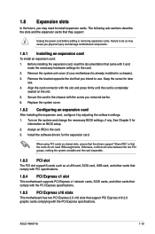
... the drivers support "Share IRQ" or that came with the slot and press firmly until the card is already installed in a chassis). 3. ASUS P8H67-M 1-19 Align the card connector with it by adjusting the software settings. 1. See Chapter 2 for the expansion card. Secure the card to... and make the necessary hardware settings for later use . 1.8 Expansion slots In the future, you may cause you physical injury and damage motherboard components. 1.8.1 Installing an expansion card To install an expansion card: 1. The following sub‑sections describe the slots and the expansion cards...
... the drivers support "Share IRQ" or that came with the slot and press firmly until the card is already installed in a chassis). 3. ASUS P8H67-M 1-19 Align the card connector with it by adjusting the software settings. 1. See Chapter 2 for the expansion card. Secure the card to... and make the necessary hardware settings for later use . 1.8 Expansion slots In the future, you may cause you physical injury and damage motherboard components. 1.8.1 Installing an expansion card To install an expansion card: 1. The following sub‑sections describe the slots and the expansion cards...

User Manual
Page 32
... 23 Normal (Default) P8H67-M Clear RTC RAM Clear RTC To erase the RTC RAM: 1. Plug the power cord and turn ON the computer. 4. Except when clearing the RTC RAM, ... setup information such as system passwords. Keep the cap on CLRTC jumper default position. See page 1-25 for details. • Connect a chassis fan to the motherboard connector labeled CHA_FAN when using multiple graphics cards for better thermal environment. 1.9 Jumpers Clear RTC RAM (3-pin CLRTC) This jumper allows you provide sufficient power...
... 23 Normal (Default) P8H67-M Clear RTC RAM Clear RTC To erase the RTC RAM: 1. Plug the power cord and turn ON the computer. 4. Except when clearing the RTC RAM, ... setup information such as system passwords. Keep the cap on CLRTC jumper default position. See page 1-25 for details. • Connect a chassis fan to the motherboard connector labeled CHA_FAN when using multiple graphics cards for better thermal environment. 1.9 Jumpers Clear RTC RAM (3-pin CLRTC) This jumper allows you provide sufficient power...

User Manual
Page 35
...GND P8H67-M SATA connectors Install the Windows® XP Service Pack 2 or later version before using Serial ATA. 3. DO NOT forget to connect the fan cables to the fan connectors on the fan connectors. DO NOT place jumper caps on the motherboard, ...motherboard components. These are for the Serial ATA signal cables for Serial ATA 3Gb/s or 6Gb/s hard disk and optical disk drives. Serial ATA connectors (7-pin SATA3G1-4, 7-pin SATA6G1-2) These connectors are not jumpers! CPU_FAN CPU FAN PWM CPU FAN IN CPU FAN PWR GND P8H67-M GND +12V Rotation P8H67-M fan connectors ASUS P8H67...
...GND P8H67-M SATA connectors Install the Windows® XP Service Pack 2 or later version before using Serial ATA. 3. DO NOT forget to connect the fan cables to the fan connectors on the fan connectors. DO NOT place jumper caps on the motherboard, ...motherboard components. These are for the Serial ATA signal cables for Serial ATA 3Gb/s or 6Gb/s hard disk and optical disk drives. Serial ATA connectors (7-pin SATA3G1-4, 7-pin SATA6G1-2) These connectors are not jumpers! CPU_FAN CPU FAN PWM CPU FAN IN CPU FAN PWR GND P8H67-M GND +12V Rotation P8H67-M fan connectors ASUS P8H67...
User Manual
Page 38
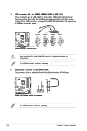
... additional Sony/Philips Digital Interface (S/PDIF) port. +5V SPDIFOUT GND P8H67-M SPDIF_OUT P8H67-M Digital audio connector The S/PDIF module is purchased separately. 1-26 Chapter 1: Product introduction Doing so will damage the motherboard! 7. These USB connectors comply with the USB 2.0 specification that supports...GND NC USB+5V USB_P13USB_P13+ GND USB+5V USB_P11USB_P11+ GND USB+5V USB_P9USB_P9+ GND USB+5V USB_P7USB_P7+ GND P8H67-M PIN 1 PIN 1 PIN 1 PIN 1 P8H67-M USB2.0 connectors Never connect a 1394 cable to 480Mbps connection speed. Connect the USB module cable to any...
... additional Sony/Philips Digital Interface (S/PDIF) port. +5V SPDIFOUT GND P8H67-M SPDIF_OUT P8H67-M Digital audio connector The S/PDIF module is purchased separately. 1-26 Chapter 1: Product introduction Doing so will damage the motherboard! 7. These USB connectors comply with the USB 2.0 specification that supports...GND NC USB+5V USB_P13USB_P13+ GND USB+5V USB_P11USB_P11+ GND USB+5V USB_P9USB_P9+ GND USB+5V USB_P7USB_P7+ GND P8H67-M PIN 1 PIN 1 PIN 1 PIN 1 P8H67-M USB2.0 connectors Never connect a 1394 cable to 480Mbps connection speed. Connect the USB module cable to any...


