User Manual
Page 11
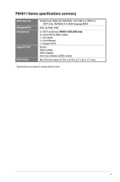
xi P8H67-I Series specifications summary BIOS features Manageability Accessories Support DVD Form factor 32 Mb Flash ROM, EFI AMI BIOS, PnP, DMI 2.0, WfM 2.0, ACPI 2.0a, SM BIOS 2.6, Multi-language BIOS WOL by PME, PXE 2 x Wi-Fi antennae (P8H67-I DELUXE only) 2 x Serial ATA 6.0Gb/s cables 1 x I/O shield 1 x User Manual 1 x Support DVD Drivers ASUS utilities ASUS Update Anti-virus software (OEM version) Mini-ITX form factor: 6.75 in x 6.75 in (17.1 cm x 17.1 cm) * Specifications are subject to change without notice.
xi P8H67-I Series specifications summary BIOS features Manageability Accessories Support DVD Form factor 32 Mb Flash ROM, EFI AMI BIOS, PnP, DMI 2.0, WfM 2.0, ACPI 2.0a, SM BIOS 2.6, Multi-language BIOS WOL by PME, PXE 2 x Wi-Fi antennae (P8H67-I DELUXE only) 2 x Serial ATA 6.0Gb/s cables 1 x I/O shield 1 x User Manual 1 x Support DVD Drivers ASUS utilities ASUS Update Anti-virus software (OEM version) Mini-ITX form factor: 6.75 in x 6.75 in (17.1 cm x 17.1 cm) * Specifications are subject to change without notice.

User Manual
Page 23
...boot/data hard disk drives to [AHCI Mode]. SATA3G_1 SATA3G_2 P8H67-I DELUXE Intel® SATA 3.0Gb/s connectors GND RSATA_TXP1 RSATA_TXN1 GND RSATA_RXP1 RSATA_RXN1 GND P8H67-I DELUXE GND RSATA_TXP2 RSATA_TXN2 GND RSATA_RXP2 RSATA_RXN2 GND ASUS P8H67-I DELUXE GND z RSATA_TXP2 RSATA_TXN2 GND RSATA_RXP2 RSATA_RXN2 GND 4. See section...Serial ATA RAID set the SATA Mode item in the BIOS to the RAID Supplementary Guide included in the folder named Manual in the BIOS to these connectors, set using these connectors. See section 2.5.4 SATA Configuration for details. 5. Intel®...
...boot/data hard disk drives to [AHCI Mode]. SATA3G_1 SATA3G_2 P8H67-I DELUXE Intel® SATA 3.0Gb/s connectors GND RSATA_TXP1 RSATA_TXN1 GND RSATA_RXP1 RSATA_RXN1 GND P8H67-I DELUXE GND RSATA_TXP2 RSATA_TXN2 GND RSATA_RXP2 RSATA_RXN2 GND ASUS P8H67-I DELUXE GND z RSATA_TXP2 RSATA_TXN2 GND RSATA_RXP2 RSATA_RXN2 GND 4. See section...Serial ATA RAID set the SATA Mode item in the BIOS to the RAID Supplementary Guide included in the folder named Manual in the BIOS to these connectors, set using these connectors. See section 2.5.4 SATA Configuration for details. 5. Intel®...
User Manual
Page 24
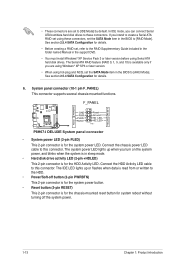
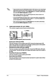
...SP3 or later version. • When using hot-plug and NCQ, set , refer to the RAID Supplementary Guide included in the folder named Manual in the support DVD. • You must install Windows® XP Service Pack 3 or later version before using these connectors. See section ...+HDLED) This 2-pin connector is for the chassis-mounted reset button for the HDD Activity LED. F_PANEL P8H67-I DELUXE PLED PWRBTN +HDLED RESET GND PWR PLEDPLED+ Reset Ground HD_LEDHD_LED+ PIN 1 P8H67-I DELUXE System panel connector • System power LED (2-pin PLED) This 2-pin connector is available only if you...
...SP3 or later version. • When using hot-plug and NCQ, set , refer to the RAID Supplementary Guide included in the folder named Manual in the support DVD. • You must install Windows® XP Service Pack 3 or later version before using these connectors. See section ...+HDLED) This 2-pin connector is for the chassis-mounted reset button for the HDD Activity LED. F_PANEL P8H67-I DELUXE PLED PWRBTN +HDLED RESET GND PWR PLEDPLED+ Reset Ground HD_LEDHD_LED+ PIN 1 P8H67-I DELUXE System panel connector • System power LED (2-pin PLED) This 2-pin connector is available only if you...

User Manual
Page 27
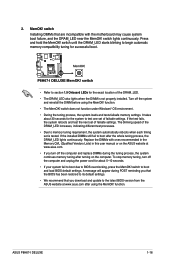
...the DRAM_LED increases, indicating different test processes. • Due to the latest BIOS version from the ASUS website at www.asus.com after the whole tuning process, the DRAM_LED lights continuously. A message will appear during the ...We recommend that are incompatible with ones recommended in the Memory QVL (Qualified Vendors Lists) in this user manual or on the computer. switch until the DRAM_LED starts blinking to boot after using the MemOK! If the ... been restored to boot and load BIOS default settings. P8H67-I DELUXE MemOK! function. ASUS P8H67-I Series 1-16
...the DRAM_LED increases, indicating different test processes. • Due to the latest BIOS version from the ASUS website at www.asus.com after the whole tuning process, the DRAM_LED lights continuously. A message will appear during the ...We recommend that are incompatible with ones recommended in the Memory QVL (Qualified Vendors Lists) in this user manual or on the computer. switch until the DRAM_LED starts blinking to boot after using the MemOK! If the ... been restored to boot and load BIOS default settings. P8H67-I DELUXE MemOK! function. ASUS P8H67-I Series 1-16
User Manual
Page 11
P8H67-I DELUXE specifications summary BIOS features Manageability Accessories Support DVD Form factor 32 Mb Flash ROM, EFI AMI BIOS, PnP, DMI 2.0, WfM 2.0, ACPI 2.0a, SM BIOS 2.6, Multi-language BIOS WOL by PME, PXE 2 x Wi-Fi antennae 2 x Serial ATA 6.0Gb/s cables 1 x I/O shield 1 x User Manual 1 x Support DVD Drivers ASUS utilities ASUS Update Anti-virus software (OEM version) Mini-ITX form factor: 6.75 in x 6.75 in (17.1 cm x 17.1 cm) * Specifications are subject to change without notice. xi
P8H67-I DELUXE specifications summary BIOS features Manageability Accessories Support DVD Form factor 32 Mb Flash ROM, EFI AMI BIOS, PnP, DMI 2.0, WfM 2.0, ACPI 2.0a, SM BIOS 2.6, Multi-language BIOS WOL by PME, PXE 2 x Wi-Fi antennae 2 x Serial ATA 6.0Gb/s cables 1 x I/O shield 1 x User Manual 1 x Support DVD Drivers ASUS utilities ASUS Update Anti-virus software (OEM version) Mini-ITX form factor: 6.75 in x 6.75 in (17.1 cm x 17.1 cm) * Specifications are subject to change without notice. xi
User Manual
Page 15
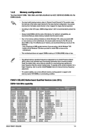
...• • • • • • • • • • • • • • • • • • ASUS P8H67-I DELUXE Motherboard Qualified Vendors Lists (QVL) DDR3-1333 MHz capability Vendors Transcend Transcend Transcend APACER CORSAIR CORSAIR G.SKILL G.SKILL GEIL GEIL GEIL HYNIX KINGMAX KINGMAX KINGMAX...the DIMM sockets. • You may operate at a higher frequency, refer to section 2.4 Ai Tweaker menu for manual memory frequency adjustment. • For system stability, use of memory, we recommend that you do any of 3GB...
...• • • • • • • • • • • • • • • • • • ASUS P8H67-I DELUXE Motherboard Qualified Vendors Lists (QVL) DDR3-1333 MHz capability Vendors Transcend Transcend Transcend APACER CORSAIR CORSAIR G.SKILL G.SKILL GEIL GEIL GEIL HYNIX KINGMAX KINGMAX KINGMAX...the DIMM sockets. • You may operate at a higher frequency, refer to section 2.4 Ai Tweaker menu for manual memory frequency adjustment. • For system stability, use of memory, we recommend that you do any of 3GB...

User Manual
Page 23
...® SATA 3.0Gb/s connectors GND RSATA_TXP1 RSATA_TXN1 GND RSATA_RXP1 RSATA_RXN1 GND P8H67-I DELUXE GND RSATA_TXP2 RSATA_TXN2 GND RSATA_RXP2 RSATA_RXN2 GND ASUS P8H67-I DELUXE GND z RSATA_TXP2 RSATA_TXN2 GND RSATA_RXP2 RSATA_RXN2 GND 4. If you are set the SATA Mode item in the BIOS to [AHCI Mode]. If you ...® XP SP3 or later version. • When using hot-plug and NCQ, set , refer to the RAID Supplementary Guide included in the folder named Manual in the BIOS to [RAID Mode]. The Serial ATA RAID feature (RAID 0, 1, 5, and 10) is available only if you intend to [IDE Mode]...
...® SATA 3.0Gb/s connectors GND RSATA_TXP1 RSATA_TXN1 GND RSATA_RXP1 RSATA_RXN1 GND P8H67-I DELUXE GND RSATA_TXP2 RSATA_TXN2 GND RSATA_RXP2 RSATA_RXN2 GND ASUS P8H67-I DELUXE GND z RSATA_TXP2 RSATA_TXN2 GND RSATA_RXP2 RSATA_RXN2 GND 4. If you are set the SATA Mode item in the BIOS to [AHCI Mode]. If you ...® XP SP3 or later version. • When using hot-plug and NCQ, set , refer to the RAID Supplementary Guide included in the folder named Manual in the BIOS to [RAID Mode]. The Serial ATA RAID feature (RAID 0, 1, 5, and 10) is available only if you intend to [IDE Mode]...
User Manual
Page 24
...system power. 1-13 Chapter 1: Product introduction Connect the HDD Activity LED cable to this connector. F_PANEL P8H67-I DELUXE PLED PWRBTN +HDLED RESET GND PWR PLEDPLED+ Reset Ground HD_LEDHD_LED+ PIN 1 P8H67-I DELUXE System panel connector • System power LED (2-pin PLED) This 2-pin connector is for the ... 2.5.4 SATA Configuration for details. • Before creating a RAID set, refer to the RAID Supplementary Guide included in the folder named Manual in the support DVD. • You must install Windows® XP Service Pack 3 or later version before using Serial ATA hard ...
...system power. 1-13 Chapter 1: Product introduction Connect the HDD Activity LED cable to this connector. F_PANEL P8H67-I DELUXE PLED PWRBTN +HDLED RESET GND PWR PLEDPLED+ Reset Ground HD_LEDHD_LED+ PIN 1 P8H67-I DELUXE System panel connector • System power LED (2-pin PLED) This 2-pin connector is for the ... 2.5.4 SATA Configuration for details. • Before creating a RAID set, refer to the RAID Supplementary Guide included in the folder named Manual in the support DVD. • You must install Windows® XP Service Pack 3 or later version before using Serial ATA hard ...
User Manual
Page 27
... of the DRAM_LED. • The DRAM_LED also lights when the DIMM is tested. If the installed DIMMs still fail to boot after using the MemOK! ASUS P8H67-I DELUXE 2. switch • Refer to section 1.9 Onboard LEDs for about 30 seconds for successful boot. A message will appear during the tuning process, the system continues memory... boot due to its default settings. • We recommend that are incompatible with ones recommended in the Memory QVL (Qualified Vendors Lists) in this user manual or on the computer.
... of the DRAM_LED. • The DRAM_LED also lights when the DIMM is tested. If the installed DIMMs still fail to boot after using the MemOK! ASUS P8H67-I DELUXE 2. switch • Refer to section 1.9 Onboard LEDs for about 30 seconds for successful boot. A message will appear during the tuning process, the system continues memory... boot due to its default settings. • We recommend that are incompatible with ones recommended in the Memory QVL (Qualified Vendors Lists) in this user manual or on the computer.

User Manual
Page 44
... and decreased average heat production. Long duration maintained [Auto] Use the and keys to manually adjust the maximum non-turbo CPU ratio. Primary Plane Current Limit [Auto] Use the and keys to +0.635V with a 0.005V interval. 2-14 ASUS P8H67-I DELUXE The values range from -0.635V to adjust the value. The valid value ranges vary...
... and decreased average heat production. Long duration maintained [Auto] Use the and keys to manually adjust the maximum non-turbo CPU ratio. Primary Plane Current Limit [Auto] Use the and keys to +0.635V with a 0.005V interval. 2-14 ASUS P8H67-I DELUXE The values range from -0.635V to adjust the value. The valid value ranges vary...

User Manual
Page 52
... [Turbo] to achieve maximum CPU fan speed. [Manual] Sets to [Manual] to 100%. The values range from 0% to disable or set CPU Fan Profile to adjust the minimum CPU fan duty cycle. Configuration options: [Ignore] [200 RPM] [300 RPM] [400 RPM] [500 RPM] [600 RPM] 2-22 ASUS P8H67-I DELUXE 2.6.3 [Disabled] [Enabled] CPU Q-Fan Control [Enabled...
... [Turbo] to achieve maximum CPU fan speed. [Manual] Sets to [Manual] to 100%. The values range from 0% to disable or set CPU Fan Profile to adjust the minimum CPU fan duty cycle. Configuration options: [Ignore] [200 RPM] [300 RPM] [400 RPM] [500 RPM] [600 RPM] 2-22 ASUS P8H67-I DELUXE 2.6.3 [Disabled] [Enabled] CPU Q-Fan Control [Enabled...


