P8H61-M2/C/SI User's Manual
Page 10
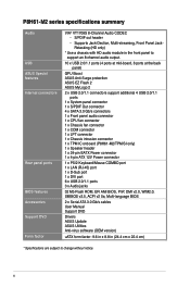
P8H61-M2 series specifications summary Audio USB ASUS Special features Internal connectors Rear panel ports BIOS features Accessories Support DVD Form factor VIA® VT1708S 8-Channel Audio ... GPU Boost ASUS Anti-Surge protection ASUS EZ Flash 2 ASUS MyLogo 2 2 x USB 2.0/1.1 connectors support additional 4 USB 2.0/1.1 ports 1 x System panel connector 1 x S/PDIF Out connector 4 x SATA 3.0 Gb/s connectors 1 x Front panel audio connector 1 x CPU fan connector 1 x Chassis fan connector 1 x COM connector 1 x LPT connector 1 x Chassis intrusion connector 1 x TPM IC onboard (P8H61-M2/TPM/SI only) 1...
P8H61-M2 series specifications summary Audio USB ASUS Special features Internal connectors Rear panel ports BIOS features Accessories Support DVD Form factor VIA® VT1708S 8-Channel Audio ... GPU Boost ASUS Anti-Surge protection ASUS EZ Flash 2 ASUS MyLogo 2 2 x USB 2.0/1.1 connectors support additional 4 USB 2.0/1.1 ports 1 x System panel connector 1 x S/PDIF Out connector 4 x SATA 3.0 Gb/s connectors 1 x Front panel audio connector 1 x CPU fan connector 1 x Chassis fan connector 1 x COM connector 1 x LPT connector 1 x Chassis intrusion connector 1 x TPM IC onboard (P8H61-M2/TPM/SI only) 1...

P8H61-M2/C/SI User's Manual
Page 11
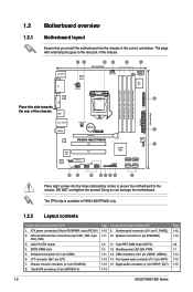
... before removing or plugging in any motherboard component. This is a reminder that the system is detached from models. SB_PWR P8H61-M2/TPM/SI ON OFF Standby Power Powered Off P8H61-M2/TPM/SI Onboard LED Chapter 1: Product introduction 1-1 The layouts vary from the power supply. If any of the items is damaged...supply is switched off or the power cord is ON, in sleep mode, or in soft-off mode. Before you for buying an ASUS® P8H61-M2 Series motherboard! The layout illustrations in this user manual are for the list of the onboard LED. Failure to do so may cause...
... before removing or plugging in any motherboard component. This is a reminder that the system is detached from models. SB_PWR P8H61-M2/TPM/SI ON OFF Standby Power Powered Off P8H61-M2/TPM/SI Onboard LED Chapter 1: Product introduction 1-1 The layouts vary from the power supply. If any of the items is damaged...supply is switched off or the power cord is ON, in sleep mode, or in soft-off mode. Before you for buying an ASUS® P8H61-M2 Series motherboard! The layout illustrations in this user manual are for the list of the onboard LED. Failure to do so may cause...
P8H61-M2/C/SI User's Manual
Page 12
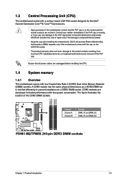
... VGA LGA1155 6 LPT 24.4cm(9.6in) LAN1_USB12 CHA_FAN Lithium Cell CMOS Power 1 AUDIO PCIEX16_1 RTL 8111E ASM 1083 P8H61-M2/TPM/SI PCI1 PCI2 Intel® H61 CHASSIS 32Mb BIOS 7 VIA 1708S SPDIF_OUT PCIEX1_1 AAFP USB910 SB_PWR USB78 F_PANEL CLRTC SPEAKER ... P8H61-M2/TPM/SI only. 1.2.2 Layout contents Connectors/Jumpers/Slots/LED 1. Chassis intrusion connector (4-1 pin CHASSIS) 8. pin SPEAKER) 1-3 11. Front panel audio connector (10-1 pin AAFP) 1-15 15 Digital audio connector (4-1 pin SPDIF_OUT) 1-13 Page 1-12 1-14 1-8 1-1 1-14 1-13 1-15 1-2 ASUS P8H61-M2 ...
... VGA LGA1155 6 LPT 24.4cm(9.6in) LAN1_USB12 CHA_FAN Lithium Cell CMOS Power 1 AUDIO PCIEX16_1 RTL 8111E ASM 1083 P8H61-M2/TPM/SI PCI1 PCI2 Intel® H61 CHASSIS 32Mb BIOS 7 VIA 1708S SPDIF_OUT PCIEX1_1 AAFP USB910 SB_PWR USB78 F_PANEL CLRTC SPEAKER ... P8H61-M2/TPM/SI only. 1.2.2 Layout contents Connectors/Jumpers/Slots/LED 1. Chassis intrusion connector (4-1 pin CHASSIS) 8. pin SPEAKER) 1-3 11. Front panel audio connector (10-1 pin AAFP) 1-15 15 Digital audio connector (4-1 pin SPDIF_OUT) 1-13 Page 1-12 1-14 1-8 1-1 1-14 1-13 1-15 1-2 ASUS P8H61-M2 ...
P8H61-M2/C/SI User's Manual
Page 13
...removal, or misplacement/loss/incorrect removal of the DDR3 DIMM sockets: DIMM_A1 DIMM_A2 DIMM_B1 DIMM_B2 P8H61-M2/TPM/SI Channel Channel A Channel B Sockets DIMM_A1 and DIMM_A2 DIMM_B1 and DIMM_B2 P8H61-M2/TPM/SI 240-pin DDR3 DIMM sockets Chapter 1: Product introduction 1-3 DDR3 modules are not bent.... The figure illustrates the location of the PnP cap. ASUS will shoulder the cost of the motherboard, ensure that ...
...removal, or misplacement/loss/incorrect removal of the DDR3 DIMM sockets: DIMM_A1 DIMM_A2 DIMM_B1 DIMM_B2 P8H61-M2/TPM/SI Channel Channel A Channel B Sockets DIMM_A1 and DIMM_A2 DIMM_B1 and DIMM_B2 P8H61-M2/TPM/SI 240-pin DDR3 DIMM sockets Chapter 1: Product introduction 1-3 DDR3 modules are not bent.... The figure illustrates the location of the PnP cap. ASUS will shoulder the cost of the motherboard, ensure that ...
P8H61-M2/C/SI User's Manual
Page 18
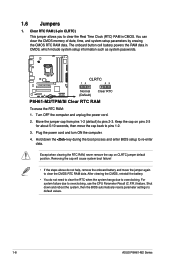
... 12 23 Normal (Default) Clear RTC P8H61-M2/TPM/SI Clear RTC RAM To erase the RTC RAM: 1. Move the jumper cap from pins 1-2 (default) to overclocking. Plug the power cord and turn ON the ... passwords. Except when clearing the RTC RAM, never remove the cap on pins 2-3 for about 5-10 seconds, then move the jumper again to default values. 1-8 ASUS P8H61-M2 Series You can clear the CMOS memory of date, time, and system setup parameters by erasing the CMOS RTC RAM data. Clear RTC RAM (3-pin...
... 12 23 Normal (Default) Clear RTC P8H61-M2/TPM/SI Clear RTC RAM To erase the RTC RAM: 1. Move the jumper cap from pins 1-2 (default) to overclocking. Plug the power cord and turn ON the ... passwords. Except when clearing the RTC RAM, never remove the cap on pins 2-3 for about 5-10 seconds, then move the jumper again to default values. 1-8 ASUS P8H61-M2 Series You can clear the CMOS memory of date, time, and system setup parameters by erasing the CMOS RTC RAM data. Clear RTC RAM (3-pin...

P8H61-M2/C/SI User's Manual
Page 20
...(24-pin EATXPWR, 4-pin ATX12V) These connectors are for a VGA monitor or other protected content. 10. ATX12V EATXPWR +12V DC +12V DC P8H61-M2/TPM/SI GND GND +3 Volts +12 Volts +12 Volts +5V Standby Power OK PIN 1 GND +5 Volts GND +5 Volts GND +3 Volts +3 Volts PIN...USB 2.0/1.1 devices. 1.7.2 Internal connectors 1. The power supply plugs are uncertain about the minimum power supply requirement for details. 1-10 ASUS P8H61-M2 Series DVI-D port. com/PowerSupplyCalculator/PSCalculator.aspx?SLanguage=en-us for your system, refer to fit these connectors in only one ...
...(24-pin EATXPWR, 4-pin ATX12V) These connectors are for a VGA monitor or other protected content. 10. ATX12V EATXPWR +12V DC +12V DC P8H61-M2/TPM/SI GND GND +3 Volts +12 Volts +12 Volts +5V Standby Power OK PIN 1 GND +5 Volts GND +5 Volts GND +3 Volts +3 Volts PIN...USB 2.0/1.1 devices. 1.7.2 Internal connectors 1. The power supply plugs are uncertain about the minimum power supply requirement for details. 1-10 ASUS P8H61-M2 Series DVI-D port. com/PowerSupplyCalculator/PSCalculator.aspx?SLanguage=en-us for your system, refer to fit these connectors in only one ...
P8H61-M2/C/SI User's Manual
Page 22
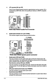
... is for the chassis-mounted reset button for system reboot without turning off the system power. 1-12 ASUS P8H61-M2 Series The HD LED lights up when you turn on IBM PC-compatible computers. LPT P8H61-M2/TPM/SI GND GND GND GND GND GND GND GND SLIN# INIT# ERR# AFD SLCT PE BUSY ACK# PD7... PD6 PD5 PD4 PD3 PD2 PD1 PD0 STB# PIN 1 P8H61-M2/TPM/SI Parallel Port Connector 5. F_PANEL PWR LED PWR BTN PLED+ PLEDPWR GND PIN 1 HD_LED+ HD_LED- LPT connector (26-1 pin LPT) The LPT (Line Printing Terminal...
... is for the chassis-mounted reset button for system reboot without turning off the system power. 1-12 ASUS P8H61-M2 Series The HD LED lights up when you turn on IBM PC-compatible computers. LPT P8H61-M2/TPM/SI GND GND GND GND GND GND GND GND SLIN# INIT# ERR# AFD SLCT PE BUSY ACK# PD7... PD6 PD5 PD4 PD3 PD2 PD1 PD0 STB# PIN 1 P8H61-M2/TPM/SI Parallel Port Connector 5. F_PANEL PWR LED PWR BTN PLED+ PLEDPWR GND PIN 1 HD_LED+ HD_LED- LPT connector (26-1 pin LPT) The LPT (Line Printing Terminal...
P8H61-M2/C/SI User's Manual
Page 24
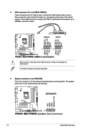
...purchased separately. 9. USB910 USB78 USB+5V USB_P10USB_P10+ GND NC USB+5V USB_P8USB_P8+ GND NC P8H61-M2/TPM/SI PIN 1 PIN 1 USB+5V USB_P9USB_P9+ GND USB+5V USB_P7USB_P7+ GND P8H61-M2/TPM/SI USB2.0 connectors Never connect a 1394 cable to hear system beeps and warnings. Doing so will... damage the motherboard! 8. The speaker allows you to the USB connectors. SPEAKER +5V GND GND Speaker Out P8H61-M2/TPM/SI PIN 1 P8H61-M2/TPM/SI Speaker Out Connector 1-14 ASUS P8H61-M2 Series The USB 2.0 module is for USB 2.0 ports. Speaker connector (4- USB connectors (10-1 pin USB78,...
...purchased separately. 9. USB910 USB78 USB+5V USB_P10USB_P10+ GND NC USB+5V USB_P8USB_P8+ GND NC P8H61-M2/TPM/SI PIN 1 PIN 1 USB+5V USB_P9USB_P9+ GND USB+5V USB_P7USB_P7+ GND P8H61-M2/TPM/SI USB2.0 connectors Never connect a 1394 cable to hear system beeps and warnings. Doing so will... damage the motherboard! 8. The speaker allows you to the USB connectors. SPEAKER +5V GND GND Speaker Out P8H61-M2/TPM/SI PIN 1 P8H61-M2/TPM/SI Speaker Out Connector 1-14 ASUS P8H61-M2 Series The USB 2.0 module is for USB 2.0 ports. Speaker connector (4- USB connectors (10-1 pin USB78,...
P8H61-M2/C/SI User's Manual
Page 28
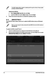
...P8H61-M-TPM/SI File Path: fs0:\ Drive fs0:\ VER: 0203 Folder Info 03/25/11 09:47a 4194304 Exit DATE: 03/25/2011 P8H61MTS.ROM File Info MODEL: Help Info VER: DATE [Enter] Select or Load [Tab] Switch [Up/Down/PageUp/PageDown/Home/End] Move [Esc] Exit [F2] Backup 2-2 ASUS P8H61-M2... Series Follow the onscreen instructions to avail all its features. Always update the utility to complete the updating process. 2.1.2 ASUS EZ Flash 2 The ASUS EZ Flash 2 feature allows you start using EZ Flash 2: 1.
...P8H61-M-TPM/SI File Path: fs0:\ Drive fs0:\ VER: 0203 Folder Info 03/25/11 09:47a 4194304 Exit DATE: 03/25/2011 P8H61MTS.ROM File Info MODEL: Help Info VER: DATE [Enter] Select or Load [Tab] Switch [Up/Down/PageUp/PageDown/Home/End] Move [Esc] Exit [F2] Backup 2-2 ASUS P8H61-M2... Series Follow the onscreen instructions to avail all its features. Always update the utility to complete the updating process. 2.1.2 ASUS EZ Flash 2 The ASUS EZ Flash 2 feature allows you start using EZ Flash 2: 1.

P8H61-M2/C/SI User's Manual
Page 30
...any user-assigned filename with no more than eight alphanumeric characters for the filename and three alphanumeric characters for DOS V1.07 Current ROM BOARD: P8H61-M2-TPM/SI VER: 0203 DATE: 03/25/2011 Update ROM BOARD: Unknown VER: Unknown DATE: Unknown PATH: A:\ BIOS backup is not write-protected...Ensure that the USB flash drive is done! The BIOS Updater backup screen appears indicating the BIOS backup process. Note Saving BIOS: 2-4 ASUS P8H61-M2 Series Welcome to Drive D (USB flash drive). Press any key to save the file. 1. ASUSTek BIOS Updater for the extension. 2.
...any user-assigned filename with no more than eight alphanumeric characters for the filename and three alphanumeric characters for DOS V1.07 Current ROM BOARD: P8H61-M2-TPM/SI VER: 0203 DATE: 03/25/2011 Update ROM BOARD: Unknown VER: Unknown DATE: Unknown PATH: A:\ BIOS backup is not write-protected...Ensure that the USB flash drive is done! The BIOS Updater backup screen appears indicating the BIOS backup process. Note Saving BIOS: 2-4 ASUS P8H61-M2 Series Welcome to Drive D (USB flash drive). Press any key to save the file. 1. ASUSTek BIOS Updater for the extension. 2.

P8H61-M2/C/SI User's Manual
Page 56
...-4555 hereby declares that may cause undesired operation. Country: TAIWAN Authorized representative in Europe: ASUS COMPUTER GmbH Address, City: HARKORT STR. 21-23, 40880 RATINGEN Country: GERMANY declare the following apparatus: Product name : Motherboard Model name : P8H61-M2/TPM/SI conform with part 15 of Conformity We, the undersigned, Manufacturer: Address, City: ASUSTek COMPUTER...
...-4555 hereby declares that may cause undesired operation. Country: TAIWAN Authorized representative in Europe: ASUS COMPUTER GmbH Address, City: HARKORT STR. 21-23, 40880 RATINGEN Country: GERMANY declare the following apparatus: Product name : Motherboard Model name : P8H61-M2/TPM/SI conform with part 15 of Conformity We, the undersigned, Manufacturer: Address, City: ASUSTek COMPUTER...

P8H61-M2/C/SI User's Manual
Page 57
...Declaration Date: May 03, 2011 Year to begin affixing CE marking:2011 Signature A-5 ASUS P8H61-M2 Series DECLARATION OF CONFORMITY Per FCC Part 2 Section 2. 1077(a) Responsible Party Name: Asus Computer International Address: 800 Corporate Way, Fremont, CA 94539. Phone/Fax No: ...operation. Country: TAIWAN Authorized representative in Europe: ASUS COMPUTER GmbH Address, City: HARKORT STR. 21-23, 40880 RATINGEN Country: GERMANY declare the following apparatus: Product name : Motherboard Model name : P8H61-M2/SI conform with the essential requirements of the following ...
...Declaration Date: May 03, 2011 Year to begin affixing CE marking:2011 Signature A-5 ASUS P8H61-M2 Series DECLARATION OF CONFORMITY Per FCC Part 2 Section 2. 1077(a) Responsible Party Name: Asus Computer International Address: 800 Corporate Way, Fremont, CA 94539. Phone/Fax No: ...operation. Country: TAIWAN Authorized representative in Europe: ASUS COMPUTER GmbH Address, City: HARKORT STR. 21-23, 40880 RATINGEN Country: GERMANY declare the following apparatus: Product name : Motherboard Model name : P8H61-M2/SI conform with the essential requirements of the following ...

P8H61-M2/C/SI User's Manual
Page 58
... must accept any interference received, including interference that the product Product Name : Motherboard Model Number : P8H61-M2/C/SI Conforms to begin affixing CE marking:2011 Signature Appendices A-6 Appendices DECLARATION OF CONFORMITY Per FCC Part 2 Section 2. 1077(a) Responsible Party Name: Asus Computer International Address: 800 Corporate Way, Fremont, CA 94539. No. 150, LI-TE RD...
... must accept any interference received, including interference that the product Product Name : Motherboard Model Number : P8H61-M2/C/SI Conforms to begin affixing CE marking:2011 Signature Appendices A-6 Appendices DECLARATION OF CONFORMITY Per FCC Part 2 Section 2. 1077(a) Responsible Party Name: Asus Computer International Address: 800 Corporate Way, Fremont, CA 94539. No. 150, LI-TE RD...


