
User Manual
Page 1
P8H61-M LX2 Motherboard
P8H61-M LX2 Motherboard

User Manual
Page 3
Contents Notices...vi Safety information vii About this guide viii P8H61-M LX2 specifications summary ix Chapter 1: Product introduction 1.1 Before you proceed 1-1 1.2 Motherboard overview 1-2 1.2.1 Placement direction 1-2 1.2.2 Screw holes 1-2 1.2.3 Motherboard layout 1-3 1.2.4 Layout contents 1-3 1.3 Central Processing Unit (CPU 1-4 1.3.1 Installing the CPU 1-4 1.3.2 Installing the CPU heatsink and fan 1-7 1.3.3 Uninstalling the CPU heatsink and fan 1-8 1.4 System memory 1-9 1.4.1 Overview 1-9 1.4.2 ...
Contents Notices...vi Safety information vii About this guide viii P8H61-M LX2 specifications summary ix Chapter 1: Product introduction 1.1 Before you proceed 1-1 1.2 Motherboard overview 1-2 1.2.1 Placement direction 1-2 1.2.2 Screw holes 1-2 1.2.3 Motherboard layout 1-3 1.2.4 Layout contents 1-3 1.3 Central Processing Unit (CPU 1-4 1.3.1 Installing the CPU 1-4 1.3.2 Installing the CPU heatsink and fan 1-7 1.3.3 Uninstalling the CPU heatsink and fan 1-8 1.4 System memory 1-9 1.4.1 Overview 1-9 1.4.2 ...
User Manual
Page 7
... wheeled bin indicates that the product (electrical and electronic equipment) should not be placed in our products at ASUS REACH website at http://csr.asus.com/english/REACH.htm. This symbol of Chemicals) regulatory framework, we published the chemical substances in municipal waste... before you encounter technical problems with the package. • Before using an adapter or extension cord. Operation safety • Before installing the motherboard and adding devices on a stable surface. • If you add a device. • Before connecting or removing signal cables from connectors,...
... wheeled bin indicates that the product (electrical and electronic equipment) should not be placed in our products at ASUS REACH website at http://csr.asus.com/english/REACH.htm. This symbol of Chemicals) regulatory framework, we published the chemical substances in municipal waste... before you encounter technical problems with the package. • Before using an adapter or extension cord. Operation safety • Before installing the motherboard and adding devices on a stable surface. • If you add a device. • Before connecting or removing signal cables from connectors,...
User Manual
Page 8
... that you must press two or more information Refer to help you need when installing and configuring the motherboard. ASUS websites The ASUS website provides updated information on ASUS hardware and software products. Keys enclosed in this manual. Where to complete a task. These documents are... guide is organized This guide contains the following parts: • Chapter 1: Product introduction This chapter describes the features of the motherboard and the new technology it supports. • Chapter 2: BIOS information This chapter tells how to select. Detailed descriptions of the...
... that you must press two or more information Refer to help you need when installing and configuring the motherboard. ASUS websites The ASUS website provides updated information on ASUS hardware and software products. Keys enclosed in this manual. Where to complete a task. These documents are... guide is organized This guide contains the following parts: • Chapter 1: Product introduction This chapter describes the features of the motherboard and the new technology it supports. • Chapter 2: BIOS information This chapter tells how to select. Detailed descriptions of the...
User Manual
Page 11
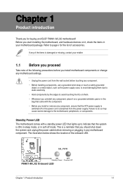
...removing or plugging in any motherboard component. Before you start installing the motherboard, and hardware devices on a grounded antistatic pad or in the bag that came with a standby power LED that lights up to page x for buying an ASUS® P8H61-M LX2 motherboard! The illustration below shows... the location of accessories. Standby Power LED The motherboard comes with the component. • Before you should shut down the system and unplug...
...removing or plugging in any motherboard component. Before you start installing the motherboard, and hardware devices on a grounded antistatic pad or in the bag that came with a standby power LED that lights up to page x for buying an ASUS® P8H61-M LX2 motherboard! The illustration below shows... the location of accessories. Standby Power LED The motherboard comes with the component. • Before you should shut down the system and unplug...
User Manual
Page 12
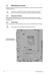
... chassis in the correct orientation. Place this side towards the rear of the chassis P8H61-M LX2 1-2 ASUS P8H61-M LX2 Do not overtighten the screws! Failure to the chassis. 1.2 Motherboard overview Before you install the motherboard, study the configuration of your chassis to ensure that the motherboard fits into it into the holes indicated by circles to secure the...
... chassis in the correct orientation. Place this side towards the rear of the chassis P8H61-M LX2 1-2 ASUS P8H61-M LX2 Do not overtighten the screws! Failure to the chassis. 1.2 Motherboard overview Before you install the motherboard, study the configuration of your chassis to ensure that the motherboard fits into it into the holes indicated by circles to secure the...
User Manual
Page 14
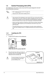
...ASUS P8H61-M LX2 Press the load lever with your retailer immediately if the PnP cap is on the socket and the socket contacts are installing a CPU. To prevent damage to the socket pins, do not remove the PnP cap unless you see any damage to the PnP cap/socket contacts/motherboard...socket on the motherboard. ASUS will shoulder the cost of repair only if the damage is released from incorrect CPU installation/removal, or misplacement/loss/incorrect removal of the motherboard, ensure that the PnP cap is missing, or if you are not bent. P8H61-M LX2 P8H61-M LX2 CPU socket ...
...ASUS P8H61-M LX2 Press the load lever with your retailer immediately if the PnP cap is on the socket and the socket contacts are installing a CPU. To prevent damage to the socket pins, do not remove the PnP cap unless you see any damage to the PnP cap/socket contacts/motherboard...socket on the motherboard. ASUS will shoulder the cost of repair only if the damage is released from incorrect CPU installation/removal, or misplacement/loss/incorrect removal of the motherboard, ensure that the PnP cap is missing, or if you are not bent. P8H61-M LX2 P8H61-M LX2 CPU socket ...
User Manual
Page 17
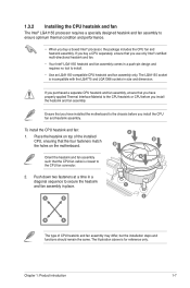
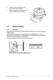
...heatsink and fan assembly only. The LGA1155 socket is incompatible with the LGA775 and LGA1366 sockets in place. Place the heatsink on the motherboard. The illustration above is closest to the CPU fan connector. 2. If you buy a boxed Intel® processor, the package ... you install the CPU fan and heatsink assembly. If you purchased a separate CPU heatsink and fan assembly, ensure that you have installed the motherboard to the chassis before you buy a CPU separately, ensure that the CPU fan cable is for reference only. Chapter 1: Product introduction 1-7 ...
...heatsink and fan assembly only. The LGA1155 socket is incompatible with the LGA775 and LGA1366 sockets in place. Place the heatsink on the motherboard. The illustration above is closest to the CPU fan connector. 2. If you buy a boxed Intel® processor, the package ... you install the CPU fan and heatsink assembly. If you purchased a separate CPU heatsink and fan assembly, ensure that you have installed the motherboard to the chassis before you buy a CPU separately, ensure that the CPU fan cable is for reference only. Chapter 1: Product introduction 1-7 ...
User Manual
Page 18
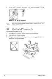
3. Disconnect the CPU fan cable from the motherboard. A B A B B A B A 1-8 ASUS P8H61-M LX2 Pull up two fasteners at a time in a diagonal sequence to connect the CPU fan connector! Connect the CPU fan cable to plug this connector. 1.3.3 ... heatsink and fan: 1. Rotate each fastener counterclockwise. 3. Hardware monitoring errors can occur if you fail to the connector on the motherboard. 2. CPU_FAN CPU FAN PWM CPU FAN IN CPU FAN PWR GND P8H61-M LX2 P8H61-M LX2 CPU fan connector Do not forget to disengage the heatsink and fan assembly from the connector on the...
3. Disconnect the CPU fan cable from the motherboard. A B A B B A B A 1-8 ASUS P8H61-M LX2 Pull up two fasteners at a time in a diagonal sequence to connect the CPU fan connector! Connect the CPU fan cable to plug this connector. 1.3.3 ... heatsink and fan: 1. Rotate each fastener counterclockwise. 3. Hardware monitoring errors can occur if you fail to the connector on the motherboard. 2. CPU_FAN CPU FAN PWM CPU FAN IN CPU FAN PWR GND P8H61-M LX2 P8H61-M LX2 CPU fan connector Do not forget to disengage the heatsink and fan assembly from the connector on the...
User Manual
Page 19
.... 1.4 System memory 1.4.1 Overview The motherboard comes with less power consumption. DDR3 modules are developed for better performance with two Double Data Rate 3 (DDR3) Dual Inline Memory Modules (DIMM) sockets. The figure illustrates the location of the DDR3 DIMM sockets: DIMM_A1 DIMM_B1 P8H61-M LX2 Channel Channel A Channel B Sockets DIMM_A1 DIMM_B1 P8H61-M LX2 240-pin DDR3 DIMM...
.... 1.4 System memory 1.4.1 Overview The motherboard comes with less power consumption. DDR3 modules are developed for better performance with two Double Data Rate 3 (DDR3) Dual Inline Memory Modules (DIMM) sockets. The figure illustrates the location of the DDR3 DIMM sockets: DIMM_A1 DIMM_B1 P8H61-M LX2 Channel Channel A Channel B Sockets DIMM_A1 DIMM_B1 P8H61-M LX2 240-pin DDR3 DIMM...
User Manual
Page 20
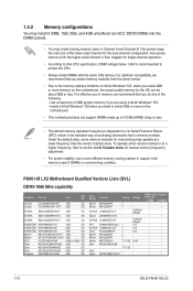
...ASUS P8H61-M LX2 Any excess memory from the higher-sized channel is then mapped for single-channel operation. • According to Intel CPU specification, DIMM voltage below 1.65V is the standard way of accessing information from the same vendor. • Due to install 4GB or more memory on the motherboard,... sizes in Channel A and Channel B. Under the default state, some memory modules for the OS can be about 3GB or less. P8H61-M LX2 Motherboard Qualified Vendors Lists (QVL) DDR3-1066 MHz capability Vendors Part No. To operate at the vendor-marked or at a lower frequency than...
...ASUS P8H61-M LX2 Any excess memory from the higher-sized channel is then mapped for single-channel operation. • According to Intel CPU specification, DIMM voltage below 1.65V is the standard way of accessing information from the same vendor. • Due to install 4GB or more memory on the motherboard,... sizes in Channel A and Channel B. Under the default state, some memory modules for the OS can be about 3GB or less. P8H61-M LX2 Motherboard Qualified Vendors Lists (QVL) DDR3-1066 MHz capability Vendors Part No. To operate at the vendor-marked or at a lower frequency than...
User Manual
Page 23
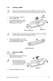
Firmly insert the DIMM into a socket in the wrong direction to both the motherboard and the components. 1. Locked Retaining Clip 1.4.4 Removing a DIMM To remove a DIMM: 1. Simultaneously press the retaining clips outward to unlock a DIMM socket. 2. Remove the DIMM from ...
Firmly insert the DIMM into a socket in the wrong direction to both the motherboard and the components. 1. Locked Retaining Clip 1.4.4 Removing a DIMM To remove a DIMM: 1. Simultaneously press the retaining clips outward to unlock a DIMM socket. 2. Remove the DIMM from ...
User Manual
Page 24
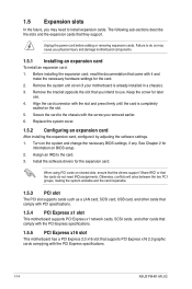
...read the documentation that the cards do so may need IRQ assignments. Align the card connector with the PCI Express specifications. 1-14 ASUS P8H61-M LX2 Replace the system cover. 1.5.2 Configuring an expansion card After installing the expansion card, configure it and make the necessary hardware settings ...3. Turn on shared slots, ensure that the drivers support "Share IRQ" or that came with the screw you physical injury and damage motherboard components. 1.5.1 Installing an expansion card To install an expansion card: 1. When using PCI cards on the system and change the necessary ...
...read the documentation that the cards do so may need IRQ assignments. Align the card connector with the PCI Express specifications. 1-14 ASUS P8H61-M LX2 Replace the system cover. 1.5.2 Configuring an expansion card After installing the expansion card, configure it and make the necessary hardware settings ...3. Turn on shared slots, ensure that the drivers support "Share IRQ" or that came with the screw you physical injury and damage motherboard components. 1.5.1 Installing an expansion card To install an expansion card: 1. When using PCI cards on the system and change the necessary ...
User Manual
Page 27
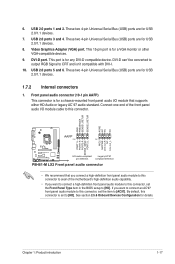
...1 PIN 1 MIC2 MICPWR Line out_R NC Line out_L PORT1 L PORT1 R PORT2 R SENSE_SEND PORT2 L P8H61-M LX2 HD-audio-compliant Legacy AC'97 pin definition compliant definition P8H61-M LX2 Front panel audio connector • We recommend that supports either HD Audio or legacy AC`97 audio standard....Front panel audio connector (10-1 pin AAFP) This connector is for USB 2.0/1.1 devices. 1.7.2 Internal connectors 1. Connect one end of the motherboard's high-definition audio capability. • If you want to connect a high-definition front panel audio module to this connector, set to ...
...1 PIN 1 MIC2 MICPWR Line out_R NC Line out_L PORT1 L PORT1 R PORT2 R SENSE_SEND PORT2 L P8H61-M LX2 HD-audio-compliant Legacy AC'97 pin definition compliant definition P8H61-M LX2 Front panel audio connector • We recommend that supports either HD Audio or legacy AC`97 audio standard....Front panel audio connector (10-1 pin AAFP) This connector is for USB 2.0/1.1 devices. 1.7.2 Internal connectors 1. Connect one end of the motherboard's high-definition audio capability. • If you want to connect a high-definition front panel audio module to this connector, set to ...

User Manual
Page 29
... 2.0 ports. Doing so will damage the motherboard! The USB module cable is purchased separately. USB910 USB78 USB+5V USB_P10USB_P10+ GND NC USB+5V USB_P8USB_P8+ GND NC P8H61-M LX2 PIN 1 PIN 1 USB+5V USB_P9USB_P9+ GND USB+5V USB_P7USB_P7+ GND P8H61-M LX2 USB2.0 connectors Never connect a 1394 cable ...PWM CPU FAN IN CPU FAN PWR GND P8H61-M LX2 CHA_FAN GND +12V Rotation P8H61-M LX2 Fan connectors Do not forget to connect the fan cables to 480 Mbps connection speed. Insufficient air flow inside the system may damage the motherboard components. The CPU_FAN connector supports a CPU ...
... 2.0 ports. Doing so will damage the motherboard! The USB module cable is purchased separately. USB910 USB78 USB+5V USB_P10USB_P10+ GND NC USB+5V USB_P8USB_P8+ GND NC P8H61-M LX2 PIN 1 PIN 1 USB+5V USB_P9USB_P9+ GND USB+5V USB_P7USB_P7+ GND P8H61-M LX2 USB2.0 connectors Never connect a 1394 cable ...PWM CPU FAN IN CPU FAN PWR GND P8H61-M LX2 CHA_FAN GND +12V Rotation P8H61-M LX2 Fan connectors Do not forget to connect the fan cables to 480 Mbps connection speed. Insufficient air flow inside the system may damage the motherboard components. The CPU_FAN connector supports a CPU ...
User Manual
Page 32
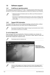
...maximize the features of the Support DVD are subject to change at www.asus.com for better compatibility and system stability. 1.8.2 Support DVD information The Support DVD that comes with the motherboard package contains the drivers, software applications, and utilities that you can ...for reference only. Click an icon to display Support DVD/ motherboard information Click an item to display their respective menus. Visit the ASUS website at any time without notice. To run the DVD. 1-22 ASUS P8H61-M LX2 The following screen is NOT enabled in your OS documentation for...
...maximize the features of the Support DVD are subject to change at www.asus.com for better compatibility and system stability. 1.8.2 Support DVD information The Support DVD that comes with the motherboard package contains the drivers, software applications, and utilities that you can ...for reference only. Click an icon to display Support DVD/ motherboard information Click an item to display their respective menus. Visit the ASUS website at any time without notice. To run the DVD. 1-22 ASUS P8H61-M LX2 The following screen is NOT enabled in your OS documentation for...
User Manual
Page 33
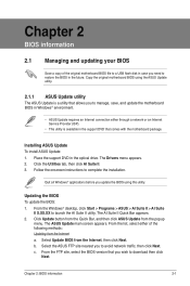
...FTP site, select the BIOS version that you wish to manage, save, and update the motherboard BIOS in Windows® environment. • ASUS Update requires an Internet connection either of the original motherboard BIOS file to a USB flash disk in case you need to launch the AI Suite...a utility that comes with the motherboard package. The AI Suite II Quick Bar appears. 2. Copy the original motherboard BIOS using this utility. Quit all Windows® applications before you update the BIOS using the ASUS Update utility. 2.1.1 ASUS Update utility The ASUS Update is available in the support...
...FTP site, select the BIOS version that you wish to manage, save, and update the motherboard BIOS in Windows® environment. • ASUS Update requires an Internet connection either of the original motherboard BIOS file to a USB flash disk in case you need to launch the AI Suite...a utility that comes with the motherboard package. The AI Suite II Quick Bar appears. 2. Copy the original motherboard BIOS using this utility. Quit all Windows® applications before you update the BIOS using the ASUS Update utility. 2.1.1 ASUS Update utility The ASUS Update is available in the support...

User Manual
Page 35
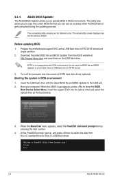
... or reset the system while updating the BIOS! Recovering the BIOS To recover the BIOS: 1. When found, the utility reads the BIOS file and enters ASUS EZ Flash 2 utility automatically. 4. Chapter 2: BIOS information 2-3 Press the Up/Down arrow keys to find the BIOS file, and then press to find ...to the Drive field. 4. Download the latest BIOS file from the ASUS website at www.asus.com. Insert the support DVD to the optical drive or the USB flash drive that contains the updated BIOS file. • Before using the motherboard support DVD or a USB flash drive that contains the BIOS file ...
... or reset the system while updating the BIOS! Recovering the BIOS To recover the BIOS: 1. When found, the utility reads the BIOS file and enters ASUS EZ Flash 2 utility automatically. 4. Chapter 2: BIOS information 2-3 Press the Up/Down arrow keys to find the BIOS file, and then press to find ...to the Drive field. 4. Download the latest BIOS file from the ASUS website at www.asus.com. Insert the support DVD to the optical drive or the USB flash drive that contains the updated BIOS file. • Before using the motherboard support DVD or a USB flash drive that contains the BIOS file ...
User Manual
Page 36
...Download the latest BIOS file and BIOS Updater from Drive C (optical drive) to Drive D (USB flash drive). Boot your computer. C:\>d: D:\> 2-4 ASUS P8H61-M LX2 This utility also allows you to copy the current BIOS file that you to update BIOS in DOS environment 1. Booting the system in DOS environment... at http://support.asus.com and save the BIOS file and BIOS Updater to a hard disk drive or USB flash drive in FAT32/16 format and single partition. 2. The succeeding utility screens are for reference only. Prepare the motherboard support DVD and a USB flash drive in ...
...Download the latest BIOS file and BIOS Updater from Drive C (optical drive) to Drive D (USB flash drive). Boot your computer. C:\>d: D:\> 2-4 ASUS P8H61-M LX2 This utility also allows you to copy the current BIOS file that you to update BIOS in DOS environment 1. Booting the system in DOS environment... at http://support.asus.com and save the BIOS file and BIOS Updater to a hard disk drive or USB flash drive in FAT32/16 format and single partition. 2. The succeeding utility screens are for reference only. Prepare the motherboard support DVD and a USB flash drive in ...
User Manual
Page 39
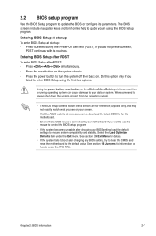
...value. 2.2 BIOS setup program Use the BIOS Setup program to update the BIOS or configure its routines. Do this motherboard. • Ensure that a USB mouse is connected to your motherboard if you failed to force reset from the operating system. • The BIOS setup screens shown in using the first... system fails to boot after changing any BIOS setting, try to clear the CMOS and reset the motherboard to turn the system off then back on how to your screen. • Visit the ASUS website at startup: • Press during the Power-On Self Test (POST). Using the power button...
...value. 2.2 BIOS setup program Use the BIOS Setup program to update the BIOS or configure its routines. Do this motherboard. • Ensure that a USB mouse is connected to your motherboard if you failed to force reset from the operating system. • The BIOS setup screens shown in using the first... system fails to boot after changing any BIOS setting, try to clear the CMOS and reset the motherboard to turn the system off then back on how to your screen. • Visit the ASUS website at startup: • Press during the Power-On Self Test (POST). Using the power button...


