P8H61-I R2.0 User's Manual
Page 11
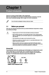
... cord from the power supply. Failure to do so may cause severe damage to page ix for buying an ASUS® P8H61-I R2.0 Onboard LED 1-1 Chapter 1: Product introduction SB_PWR P8H61-I R2.0 ON OFF Standby Power Powered Off P8H61-I R2.0 motherboard! The illustration below shows the location of the onboard LED. Before you uninstall any component, place it...
... cord from the power supply. Failure to do so may cause severe damage to page ix for buying an ASUS® P8H61-I R2.0 Onboard LED 1-1 Chapter 1: Product introduction SB_PWR P8H61-I R2.0 ON OFF Standby Power Powered Off P8H61-I R2.0 motherboard! The illustration below shows the location of the onboard LED. Before you uninstall any component, place it...
P8H61-I R2.0 User's Manual
Page 12
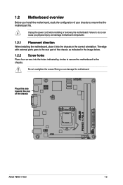
... of your chassis to the chassis. Unplug the power cord before installing or removing the motherboard. Place this side towards the rear of the chassis P8H61-I R2.0 ASUS P8H61-I R2.0 1-2 1.2 Motherboard overview Before you physical injury and damage motherboard components. 1.2.1 Placement direction When installing the motherboard, place it into the holes indicated by circles to...
... of your chassis to the chassis. Unplug the power cord before installing or removing the motherboard. Place this side towards the rear of the chassis P8H61-I R2.0 ASUS P8H61-I R2.0 1-2 1.2 Motherboard overview Before you physical injury and damage motherboard components. 1.2.1 Placement direction When installing the motherboard, place it into the holes indicated by circles to...
P8H61-I R2.0 User's Manual
Page 14
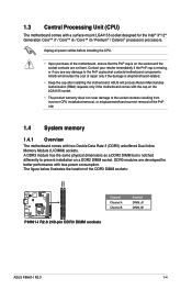
... incorrect CPU installation/removal, or misplacement/loss/incorrect removal of the DDR3 DIMM sockets: DIMMA1 DIMMB1 Channel Channel A Channel B Sockets DIMM_A1 DIMM_B1 P8H61-I R2.0 P8H61-I R2.0 240-pin DDR3 DIMM sockets ASUS P8H61-I R2.0 1-4 ASUS will shoulder the cost of the motherboard, ensure that the PnP cap is shipment/transit-related. • Keep the cap after installing the...
... incorrect CPU installation/removal, or misplacement/loss/incorrect removal of the DDR3 DIMM sockets: DIMMA1 DIMMB1 Channel Channel A Channel B Sockets DIMM_A1 DIMM_B1 P8H61-I R2.0 P8H61-I R2.0 240-pin DDR3 DIMM sockets ASUS P8H61-I R2.0 1-4 ASUS will shoulder the cost of the motherboard, ensure that the PnP cap is shipment/transit-related. • Keep the cap after installing the...
P8H61-I R2.0 User's Manual
Page 16
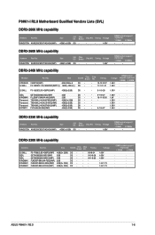
P8H61-I R2.0 1-6 Timing Voltage 4GB(2 x 2GB) DS - - - 1.65V DIMM socket support (Optional) 1 DIMM 2 DIMMs • • DDR3-2400 MHz capability Vendors Part No. KINGSTON KHX2250C9D3T1K2/4GX(XMP) ... No. Voltage 1.65V 1.65V 1.65V 1.5V-1.7V 1.5V-1.7V DIMM socket support (Optional) 1 DIMM 2 DIMM · · · · · · · · · · ASUS P8H61-I R2.0 Motherboard Qualified Vendors Lists (QVL) DDR3-2666 MHz capability Vendors Part No. Timing DS DS DS DS DS DS - - 8-8-8-24 - 9-10-9-28 - 9-11-9-28 ---- Timing...
P8H61-I R2.0 1-6 Timing Voltage 4GB(2 x 2GB) DS - - - 1.65V DIMM socket support (Optional) 1 DIMM 2 DIMMs • • DDR3-2400 MHz capability Vendors Part No. KINGSTON KHX2250C9D3T1K2/4GX(XMP) ... No. Voltage 1.65V 1.65V 1.65V 1.5V-1.7V 1.5V-1.7V DIMM socket support (Optional) 1 DIMM 2 DIMM · · · · · · · · · · ASUS P8H61-I R2.0 Motherboard Qualified Vendors Lists (QVL) DDR3-2666 MHz capability Vendors Part No. Timing DS DS DS DS DS DS - - 8-8-8-24 - 9-10-9-28 - 9-11-9-28 ---- Timing...
P8H61-I R2.0 User's Manual
Page 22
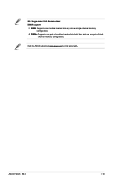
channel memory configuration. ASUS P8H61-I R2.0 1-12 SS: Single-sided / DS: Double-sided DIMM support: • 1 DIMM: Supports one module inserted into any slot as single-channel memory configuration. • 2 DIMMs: Supports one pair of modules inserted into both blue slots as one pair of dual- Visit the ASUS website at www.asus.com for the latest QVL.
channel memory configuration. ASUS P8H61-I R2.0 1-12 SS: Single-sided / DS: Double-sided DIMM support: • 1 DIMM: Supports one module inserted into any slot as single-channel memory configuration. • 2 DIMMs: Supports one pair of modules inserted into both blue slots as one pair of dual- Visit the ASUS website at www.asus.com for the latest QVL.
P8H61-I R2.0 User's Manual
Page 24
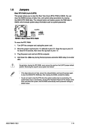
... and unplug the power cord. 2. Shut down the key during the boot process and enter BIOS setup to pins 2-3. CLRTC 12 23 P8H61-I R2.0 Normal (Default) Clear RTC P8H61-I R2.0 1-14 Plug the power cord and turn ON the computer. 4. After clearing the CMOS, reinstall the battery. • You do ...when the system crashes due to clear the Real Time Clock (RTC) RAM in CMOS, which include system setup information such as system passwords. ASUS P8H61-I R2.0 Clear RTC RAM To erase the RTC RAM: 1. You can clear the CMOS memory of date, time, and system setup parameters by ...
... and unplug the power cord. 2. Shut down the key during the boot process and enter BIOS setup to pins 2-3. CLRTC 12 23 P8H61-I R2.0 Normal (Default) Clear RTC P8H61-I R2.0 1-14 Plug the power cord and turn ON the computer. 4. After clearing the CMOS, reinstall the battery. • You do ...when the system crashes due to clear the Real Time Clock (RTC) RAM in CMOS, which include system setup information such as system passwords. ASUS P8H61-I R2.0 Clear RTC RAM To erase the RTC RAM: 1. You can clear the CMOS memory of date, time, and system setup parameters by ...
P8H61-I R2.0 User's Manual
Page 26
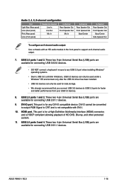
... Out Bass/Center - 8-channel Rear Speaker Out Front Speaker Out Bass/Center Side Speaker Out To configure an 8-channel audio output: Use a chassis with DVI-I R2.0 1-16 Audio 2, 4, 6, 8-channel configuration Port Headset 2-channel 4-channel Light Blue (Rear panel) Lime (Rear panel) Pink (Rear panel) Lime (Front panel) Line In Line Out...
... Out Bass/Center - 8-channel Rear Speaker Out Front Speaker Out Bass/Center Side Speaker Out To configure an 8-channel audio output: Use a chassis with DVI-I R2.0 1-16 Audio 2, 4, 6, 8-channel configuration Port Headset 2-channel 4-channel Light Blue (Rear panel) Lime (Rear panel) Pink (Rear panel) Lime (Front panel) Line In Line Out...
P8H61-I R2.0 User's Manual
Page 28
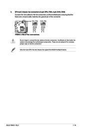
... the fan connectors. Insufficient air flow inside the system may damage the motherboard components. Only the 4-pin CPU fan and chassis fan support the ASUS FanXpert feature. ASUS P8H61-I R2.0 CPU FAN PWM CPU FAN IN CPU FAN PWR GND CHA FAN PWM CPU FAN IN CHA FAN PWR GND 3. These are not jumpers...! CPU_FAN CHA_FAN P8H61-I R2.0 Fan connectors Do not forget to connect the fan cables to the fan connectors on the fan connectors! P8H61-I R2.0 1-18 Do not place ...
... the fan connectors. Insufficient air flow inside the system may damage the motherboard components. Only the 4-pin CPU fan and chassis fan support the ASUS FanXpert feature. ASUS P8H61-I R2.0 CPU FAN PWM CPU FAN IN CPU FAN PWR GND CHA FAN PWM CPU FAN IN CHA FAN PWR GND 3. These are not jumpers...! CPU_FAN CHA_FAN P8H61-I R2.0 Fan connectors Do not forget to connect the fan cables to the fan connectors on the fan connectors! P8H61-I R2.0 1-18 Do not place ...
P8H61-I R2.0 User's Manual
Page 30
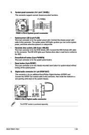
... audio connector (4-1 pin SPDIF-OUT) This connector is for an additional Sony/Philips Digital Interface (S/PDIF) port. P8H61-I R2.0 +5V SPDIFOUT GND SPDIF_OUT P8H61-I R2.0 1-20 The system power LED lights up or flashes when data is for system reboot without turning off button ...RESET) This 2-pin connector is purchased separately. System panel connector (10-1 pin F_PANEL) This connector supports several chassis-mounted functions. ASUS P8H61-I R2.0 Digital audio connector The S/PDIF module is for the chassis-mounted reset button for the system power LED. Connect the HDD ...
... audio connector (4-1 pin SPDIF-OUT) This connector is for an additional Sony/Philips Digital Interface (S/PDIF) port. P8H61-I R2.0 +5V SPDIFOUT GND SPDIF_OUT P8H61-I R2.0 1-20 The system power LED lights up or flashes when data is for system reboot without turning off button ...RESET) This 2-pin connector is purchased separately. System panel connector (10-1 pin F_PANEL) This connector supports several chassis-mounted functions. ASUS P8H61-I R2.0 Digital audio connector The S/PDIF module is for the chassis-mounted reset button for the system power LED. Connect the HDD ...
P8H61-I R2.0 User's Manual
Page 32
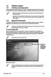
... the BIN folder. Refer to your computer, browse the contents of the Support DVD to avail of all motherboard features. Visit the ASUS website at any time without notice. Click Drivers, Utilities, Make Disk, Manual,and Contact tabs to maximize the features of your computer... Place the Support DVD into the optical drive. If Autorun is for updates. ASUS P8H61-I R2.0 1-22 Always install the latest OS version and corresponding updates to display their respective menus. The contents of ASUS motherboards. The following screen is enabled in your hardware. • Motherboard settings ...
... the BIN folder. Refer to your computer, browse the contents of the Support DVD to avail of all motherboard features. Visit the ASUS website at any time without notice. Click Drivers, Utilities, Make Disk, Manual,and Contact tabs to maximize the features of your computer... Place the Support DVD into the optical drive. If Autorun is for updates. ASUS P8H61-I R2.0 1-22 Always install the latest OS version and corresponding updates to display their respective menus. The contents of ASUS motherboards. The following screen is enabled in your hardware. • Motherboard settings ...
P8H61-I R2.0 User's Manual
Page 34
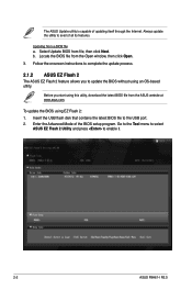
...updating itself through the Internet. Updating from file, then click Next. Follow the onscreen instructions to complete the update process. 2.1.2 ASUS EZ Flash 2 The ASUS EZ Flash 2 feature allows you start using this utility, download the latest BIOS file from the Open window, then click Open..... Select Update BIOS from a BIOS file a. Insert the USB flash disk that contains the latest BIOS file to enable it. 2-2 ASUS P8H61-I R2.0 The ASUS Update utility is capable of the BIOS setup program. Always update the utility to update the BIOS without using EZ Flash 2: 1. Locate...
...updating itself through the Internet. Updating from file, then click Next. Follow the onscreen instructions to complete the update process. 2.1.2 ASUS EZ Flash 2 The ASUS EZ Flash 2 feature allows you start using this utility, download the latest BIOS file from the Open window, then click Open..... Select Update BIOS from a BIOS file a. Insert the USB flash disk that contains the latest BIOS file to enable it. 2-2 ASUS P8H61-I R2.0 The ASUS Update utility is capable of the BIOS setup program. Always update the utility to update the BIOS without using EZ Flash 2: 1. Locate...
P8H61-I R2.0 User's Manual
Page 36
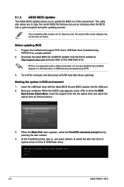
...: XXXXXXXXXXXXXXXX Enter Setup ↑ and ↓ to move selection ENTER to select boot device ESC to Drive D (USB flash drive). C:\>d: D:\> 2-4 ASUS P8H61-I R2.0 Do not save them on a single partition. 2. Turn off the computer and disconnect all SATA hard disk drives (optional). At the FreeDOS prompt, ... pressing the item number. 4. Before updating BIOS 1. NTFS is not supported under a DOS environment. Boot your computer. 2.1.4 ASUS BIOS Updater The ASUS BIOS Updater allows you can use as a backup when the BIOS fails or gets corrupted during the updating process. This utility ...
...: XXXXXXXXXXXXXXXX Enter Setup ↑ and ↓ to move selection ENTER to select boot device ESC to Drive D (USB flash drive). C:\>d: D:\> 2-4 ASUS P8H61-I R2.0 Do not save them on a single partition. 2. Turn off the computer and disconnect all SATA hard disk drives (optional). At the FreeDOS prompt, ... pressing the item number. 4. Before updating BIOS 1. NTFS is not supported under a DOS environment. Boot your computer. 2.1.4 ASUS BIOS Updater The ASUS BIOS Updater allows you can use as a backup when the BIOS fails or gets corrupted during the updating process. This utility ...
P8H61-I R2.0 User's Manual
Page 38
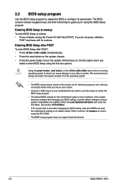
... with its routines. Do this option only if you failed to erase the RTC RAM. • The BIOS setup program does not support bluetooth devices. 2-6 ASUS P8H61-I R2.0 Refer to ensure system compatibility and stability. Entering BIOS Setup after POST To enter BIOS Setup after changing any BIOS settings, load the default settings...
... with its routines. Do this option only if you failed to erase the RTC RAM. • The BIOS setup program does not support bluetooth devices. 2-6 ASUS P8H61-I R2.0 Refer to ensure system compatibility and stability. Entering BIOS Setup after POST To enter BIOS Setup after changing any BIOS settings, load the default settings...

P8H61-I R2.0 User's Manual
Page 40
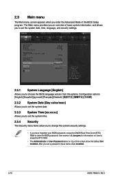
Refer to configure the BIOS settings. To access the EZ Mode, click Exit, then select ASUS EZ Mode. Back button Menu items Menu bar General help Submenu item Pop-up window Configuration Scroll bar Navigation keys fields Menu bar The menu .... The figure below shows an example of the screen has the following sections for special functions For selecting the exit options and loading default settings 2-8 ASUS P8H61-I R2.0 Advanced Mode The Advanced Mode provides advanced options for experienced end-users to the following main items: Main Ai Tweaker Advanced Monitor Boot Tool Exit...
Refer to configure the BIOS settings. To access the EZ Mode, click Exit, then select ASUS EZ Mode. Back button Menu items Menu bar General help Submenu item Pop-up window Configuration Scroll bar Navigation keys fields Menu bar The menu .... The figure below shows an example of the screen has the following sections for special functions For selecting the exit options and loading default settings 2-8 ASUS P8H61-I R2.0 Advanced Mode The Advanced Mode provides advanced options for experienced end-users to the following main items: Main Ai Tweaker Advanced Monitor Boot Tool Exit...
P8H61-I R2.0 User's Manual
Page 42
... to set the system date, time, language, and security settings. 2.3.1 System Language [English] Allows you enter the Advanced Mode of the screen show Installed. 2-10 ASUS P8H61-I R2.0
... to set the system date, time, language, and security settings. 2.3.1 System Language [English] Allows you enter the Advanced Mode of the screen show Installed. 2-10 ASUS P8H61-I R2.0
P8H61-I R2.0 User's Manual
Page 44
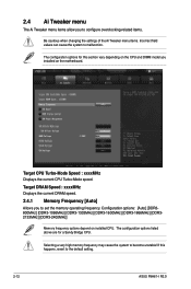
...] [DDR32133MHz] [DDR3-2400MHz] Memory frequency options depend on the motherboard. The configuration options listed above are for this happens, revert to the default setting. 2-12 ASUS P8H61-I R2.0 Selecting a very high memory frequency may cause the system to become unstable! The configuration options for a Sandy Bridge CPU. Target CPU Turbo-Mode Speed : xxxxMHz...
...] [DDR32133MHz] [DDR3-2400MHz] Memory frequency options depend on the motherboard. The configuration options listed above are for this happens, revert to the default setting. 2-12 ASUS P8H61-I R2.0 Selecting a very high memory frequency may cause the system to become unstable! The configuration options for a Sandy Bridge CPU. Target CPU Turbo-Mode Speed : xxxxMHz...
P8H61-I R2.0 User's Manual
Page 46
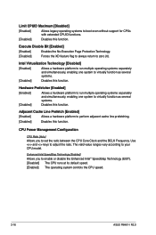
.... We recommend you install the DIMMs with the voltage requirement below 1.65V. 2.4.7 VCCSA Voltage [Auto] Allows you to work stably under high voltage settings. 2-14 ASUS P8H61-I R2.0 The values range from 1.185V to set the VCCIO voltage. According to Intel CPU specification, DIMMs with a 0.005V interval. The values range from 0V to...
.... We recommend you install the DIMMs with the voltage requirement below 1.65V. 2.4.7 VCCSA Voltage [Auto] Allows you to work stably under high voltage settings. 2-14 ASUS P8H61-I R2.0 The values range from 1.185V to set the VCCIO voltage. According to Intel CPU specification, DIMMs with a 0.005V interval. The values range from 0V to...
P8H61-I R2.0 User's Manual
Page 48
... disable the Enhanced Intel® SpeedStep Technology (EIST). [Disabled] The CPU runs at its default speed. [Enabled] The operating system controls the CPU speed. 2-16 ASUS P8H61-I R2.0 Adjacent Cache Line Prefetch [Enabled] [Enabled] Allows a hardware platform to adjust the ratio. Use and keys to perform adjacent cache line prefetching. [Disabled] Disables this...
... disable the Enhanced Intel® SpeedStep Technology (EIST). [Disabled] The CPU runs at its default speed. [Enabled] The operating system controls the CPU speed. 2-16 ASUS P8H61-I R2.0 Adjacent Cache Line Prefetch [Enabled] [Enabled] Allows a hardware platform to adjust the ratio. Use and keys to perform adjacent cache line prefetching. [Disabled] Disables this...

P8H61-I R2.0 User's Manual
Page 50
... disable the ISCT configuration. Intel(R) Smart Connect Technology ISCT Configuration [Disabled] Allows you to support the Intel(R) Rapid Start Technology. Configuration options: [Enabled] [Disabled] 2-18 ASUS P8H61-I R2.0 Configuration options: [Enabled] [Disabled] Active Memory Threshold [x] This item appears only when you set the Active Memory Threshold. Configuration options: [Immediately] [1 minute] [2 minute] [5 minute] [10...
... disable the ISCT configuration. Intel(R) Smart Connect Technology ISCT Configuration [Disabled] Allows you to support the Intel(R) Rapid Start Technology. Configuration options: [Enabled] [Disabled] 2-18 ASUS P8H61-I R2.0 Configuration options: [Enabled] [Disabled] Active Memory Threshold [x] This item appears only when you set the Active Memory Threshold. Configuration options: [Immediately] [1 minute] [2 minute] [5 minute] [10...

P8H61-I R2.0 User's Manual
Page 52
... internal graphics device will keep 64MB. And the memory size for operating systems without an EHCI hand‑off feature. [Disabled] Disables the function. 2-20 ASUS P8H61-I R2.0
... internal graphics device will keep 64MB. And the memory size for operating systems without an EHCI hand‑off feature. [Disabled] Disables the function. 2-20 ASUS P8H61-I R2.0


