
User Manual
Page 9
P7P55D-E LX specifications summary CPU Chipset Memory Expansion Slots Storage LAN USB Audio LGA1156 socket for Intel® Core™ i7 / Core™ i5 / Core™ i3 processors Supports Intel® Turbo Boost Technology * Refer to www.asus.com for the Memory QVL (Qualified Vendors Lists) 1 x... back panel) Intel® P55 Express Chipset: - 12 x USB 2.0 ports (6 ports at mid-board, 6 ports at back I/O (continued on -the-go) Marvell® PCIe SATA 6Gb/s controller: - 2 x SATA 6.0 Gb/s ports (gray) Realtek® 8112L Gigabit LAN controller featuring AI NET2 NEC USB 3.0 controller: ...
P7P55D-E LX specifications summary CPU Chipset Memory Expansion Slots Storage LAN USB Audio LGA1156 socket for Intel® Core™ i7 / Core™ i5 / Core™ i3 processors Supports Intel® Turbo Boost Technology * Refer to www.asus.com for the Memory QVL (Qualified Vendors Lists) 1 x... back panel) Intel® P55 Express Chipset: - 12 x USB 2.0 ports (6 ports at mid-board, 6 ports at back I/O (continued on -the-go) Marvell® PCIe SATA 6Gb/s controller: - 2 x SATA 6.0 Gb/s ports (gray) Realtek® 8112L Gigabit LAN controller featuring AI NET2 NEC USB 3.0 controller: ...

User Manual
Page 15
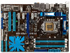
1.5.3 Motherboard layout Ensure that you install the motherboard into the chassis in the correct orientation. Marvell® Serial ATA 6.0 Gb/s connectors (7-pin SATA_6G_1/2 [gray]) Page Connectors/Jumpers/Slots/LED 1-4 9. Front panel audio connector (10-1 pin AAFP) 1-23 1-27 14. ... ports goes to the rear part of the chassis. 1.5.4 Layout contents Connectors/Jumpers/Slots/LED 1. MemOK! Serial port connector (10-1 pin COM1) 1-25 ASUS P7P55D-E LX 1-3 Place this side towards the rear of the chassis. USB connectors (10-1 pin USB910, USB1112, USB1314) 1-9 11.
1.5.3 Motherboard layout Ensure that you install the motherboard into the chassis in the correct orientation. Marvell® Serial ATA 6.0 Gb/s connectors (7-pin SATA_6G_1/2 [gray]) Page Connectors/Jumpers/Slots/LED 1-4 9. Front panel audio connector (10-1 pin AAFP) 1-23 1-27 14. ... ports goes to the rear part of the chassis. 1.5.4 Layout contents Connectors/Jumpers/Slots/LED 1. MemOK! Serial port connector (10-1 pin COM1) 1-25 ASUS P7P55D-E LX 1-3 Place this side towards the rear of the chassis. USB connectors (10-1 pin USB910, USB1112, USB1314) 1-9 11.

User Manual
Page 38
...drives. • When using hot-plug and NCQ, set to section Onboard Devices Configuration for an additional Sony/Philips Digital Interface (S/PDIF) port(s). Marvell® Serial ATA 6.0 Gb/s connectors (7-pin SATA_6G_1/2 [gray]) These connectors connect to Serial ATA 6.0 Gb/s hard disk drives via Serial ATA... 6.0 Gb/s signal cables. • These connectors are set the Marvell 9123 Controller item in the BIOS to a slot opening at the back of the system chassis. Digital audio connector (4-1 pin SPDIF_OUT) This...
...drives. • When using hot-plug and NCQ, set to section Onboard Devices Configuration for an additional Sony/Philips Digital Interface (S/PDIF) port(s). Marvell® Serial ATA 6.0 Gb/s connectors (7-pin SATA_6G_1/2 [gray]) These connectors connect to Serial ATA 6.0 Gb/s hard disk drives via Serial ATA... 6.0 Gb/s signal cables. • These connectors are set the Marvell 9123 Controller item in the BIOS to a slot opening at the back of the system chassis. Digital audio connector (4-1 pin SPDIF_OUT) This...

User Manual
Page 60
...] Disables Realtek LAN Controller. Configuration options: [Disabled] [3F8/IRQ4] [2F8/IRQ3] [3E8/IRQ4] [2E8/IRQ3] Marvell 9123 Controller [IDE Mode] [Disabled] Disables the Marvell controller. [IDE Mode] Set to [IDE Mode] when you want to use the Serial ATA hard disk drives as Parallel...Interface). Serial Port1 Address [3F8/IRQ4] Allows you enable the previous item. [Disabled] Disables Marvell controller Boot ROM. [Enabled] Enables Marvell controller Boot ROM. 2-18 Chapter 2: BIOS information Marvell 9123 Boot ROM [Auto] This item appears only when you to select the Serial Port1 ...
...] Disables Realtek LAN Controller. Configuration options: [Disabled] [3F8/IRQ4] [2F8/IRQ3] [3E8/IRQ4] [2E8/IRQ3] Marvell 9123 Controller [IDE Mode] [Disabled] Disables the Marvell controller. [IDE Mode] Set to [IDE Mode] when you want to use the Serial ATA hard disk drives as Parallel...Interface). Serial Port1 Address [3F8/IRQ4] Allows you enable the previous item. [Disabled] Disables Marvell controller Boot ROM. [Enabled] Enables Marvell controller Boot ROM. 2-18 Chapter 2: BIOS information Marvell 9123 Boot ROM [Auto] This item appears only when you to select the Serial Port1 ...