
User Manual
Page 3
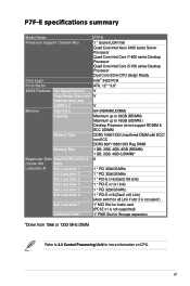
... P7F-E specifications summary xi Chapter 1: Product introduction 1.1 Welcome 1-3 1.2 Package contents 1-3 1.3 Serial number label 1-4 1.4 Special features 1-4 1.4.1 Product highlights 1-4 1.4.2 Innovative ASUS features 1-6 Chapter 2: Hardware information 2.1 Before you proceed 2-3 2.2 Motherboard overview 2-5 2.2.1 Placement direction 2-5 2.2.2 Screw holes 2-5 2.2.3 Motherboard ...DIMM 2-16 2.5 Expansion slots 2-17 2.5.1 Installing an expansion card 2-17 2.5.2 Configuring an expansion card 2-17 2.5.3 Interrupt assignments 2-18 2.5.4 MIO PCIE slot 2-18 2.5.5 PCI Express x16 slot (x8...
... P7F-E specifications summary xi Chapter 1: Product introduction 1.1 Welcome 1-3 1.2 Package contents 1-3 1.3 Serial number label 1-4 1.4 Special features 1-4 1.4.1 Product highlights 1-4 1.4.2 Innovative ASUS features 1-6 Chapter 2: Hardware information 2.1 Before you proceed 2-3 2.2 Motherboard overview 2-5 2.2.1 Placement direction 2-5 2.2.2 Screw holes 2-5 2.2.3 Motherboard ...DIMM 2-16 2.5 Expansion slots 2-17 2.5.1 Installing an expansion card 2-17 2.5.2 Configuring an expansion card 2-17 2.5.3 Interrupt assignments 2-18 2.5.4 MIO PCIE slot 2-18 2.5.5 PCI Express x16 slot (x8...
User Manual
Page 4
... 2.5.7 PCI Express x1 slot 2-19 2.5.8 PCI slots 2-19 2.5.9 PIKE slot 2-19 2.5.10 Installing an ASUS PIKE RAID card 2-20 2.5.11 Installing i Button 2-21 2.5.12 Installing ASMB4 management board 2-21 2.5.13 Connect Thermal sensor cable 2-22 2.5.14 Installing the audio card 2-22 2.6 Jumpers 2-23 2.7 Connectors 2-27 2.7.1 Rear panel connectors 2-27 2.7.2 Internal connectors 2-28 Chapter...
... 2.5.7 PCI Express x1 slot 2-19 2.5.8 PCI slots 2-19 2.5.9 PIKE slot 2-19 2.5.10 Installing an ASUS PIKE RAID card 2-20 2.5.11 Installing i Button 2-21 2.5.12 Installing ASMB4 management board 2-21 2.5.13 Connect Thermal sensor cable 2-22 2.5.14 Installing the audio card 2-22 2.6 Jumpers 2-23 2.7 Connectors 2-27 2.7.1 Rear panel connectors 2-27 2.7.2 Internal connectors 2-28 Chapter...

User Manual
Page 7
...Commission Statement This device complies with Part 15 of Chemicals) regulatory framework, we published the chemical substances in our products at ASUS REACH website at http://green.asus.com/english/REACH.htm. The use of shielded cables for radio noise emissions from that to which can radiate radio frequency... been tested and found to comply with the limits for a Class B digital device, pursuant to Part 15 of the monitor to the graphics card is encouraged to try to correct the interference by the party responsible for help. However, there is connected. • Consult the dealer or ...
...Commission Statement This device complies with Part 15 of Chemicals) regulatory framework, we published the chemical substances in our products at ASUS REACH website at http://green.asus.com/english/REACH.htm. The use of shielded cables for radio noise emissions from that to which can radiate radio frequency... been tested and found to comply with the limits for a Class B digital device, pursuant to Part 15 of the monitor to the graphics card is encouraged to try to correct the interference by the party responsible for help. However, there is connected. • Consult the dealer or ...
User Manual
Page 11
...P7F-E Processor Support / System Bus 1 * Socket LGA1156 Quad Core Intel Xeon 3400 series Server Processor Quad Core Intel Core i7-800 series Desktop Processor Quad Core Intel Core i5-700 series Desktop Processor Dual Core 32nm CPU design Ready Core Logic Intel® 3420 PCH Form Factor ATX, 12" * 9.6" ASUS... 1 * PCI-E x16 (Gen2 x16 Link) (Auto switch to x8 Link if slot 3 is occupied ) Slot Loacation 7 1* MIO Slot for Audio card (PCI-E x1 is not supported) Additional Slot 1 1* PIKE Slot for Stroage expansion *Down from 1066 or 1333 MHz DIMM Refer to 2.3 Central Processing ...
...P7F-E Processor Support / System Bus 1 * Socket LGA1156 Quad Core Intel Xeon 3400 series Server Processor Quad Core Intel Core i7-800 series Desktop Processor Quad Core Intel Core i5-700 series Desktop Processor Dual Core 32nm CPU design Ready Core Logic Intel® 3420 PCH Form Factor ATX, 12" * 9.6" ASUS... 1 * PCI-E x16 (Gen2 x16 Link) (Auto switch to x8 Link if slot 3 is occupied ) Slot Loacation 7 1* MIO Slot for Audio card (PCI-E x1 is not supported) Additional Slot 1 1* PIKE Slot for Stroage expansion *Down from 1066 or 1333 MHz DIMM Refer to 2.3 Central Processing ...
User Manual
Page 12
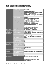
P7F-E specifications summary Storage Networking Graphics Onboard I/O Connectors Rear I/O Connectors Management Solution Monitoring Environment SATA Controller SAS Controller LAN VGA PSU Connector USB Connectors Fan Header ... 1064E 4-port SAS card (Support FW RAID 0,1,1E) ASUS PIKE 1068E 8-port SAS card (support FW RAID 0, 1, 1E) ASUS PIKE 1078 8-port SAS card (support integrated H/W RAID 0, 1, 10, 5, 50, 6, 60) ASUS PIKE 6480 8-port SAS card (Support FW RAID 0,1,10, 5) 2 * Intel 82574L + 1 * Mgmt LAN Aspeed AST2050 8MB 24-pin ATX power connector + 8-pin ATX 12V power connector 3 (support 5 USB...
P7F-E specifications summary Storage Networking Graphics Onboard I/O Connectors Rear I/O Connectors Management Solution Monitoring Environment SATA Controller SAS Controller LAN VGA PSU Connector USB Connectors Fan Header ... 1064E 4-port SAS card (Support FW RAID 0,1,1E) ASUS PIKE 1068E 8-port SAS card (support FW RAID 0, 1, 1E) ASUS PIKE 1078 8-port SAS card (support integrated H/W RAID 0, 1, 10, 5, 50, 6, 60) ASUS PIKE 6480 8-port SAS card (Support FW RAID 0,1,10, 5) 2 * Intel 82574L + 1 * Mgmt LAN Aspeed AST2050 8MB 24-pin ATX power connector + 8-pin ATX 12V power connector 3 (support 5 USB...
User Manual
Page 15
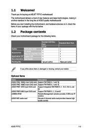
.... Cables SATA data cable Standard Gift Box Pack P7F-E 6 Accessories IO shield 1 Plate for buying an ASUS® P7F-E motherboard! Thank you start installing the motherboard, and hardware devices on it another standout in your package with the list below. 1.2 Package contents Check your retailer. ASUS MIO audio card Discrete 8 channel audio card provides clearest high quality sounds...
.... Cables SATA data cable Standard Gift Box Pack P7F-E 6 Accessories IO shield 1 Plate for buying an ASUS® P7F-E motherboard! Thank you start installing the motherboard, and hardware devices on it another standout in your package with the list below. 1.2 Package contents Check your retailer. ASUS MIO audio card Discrete 8 channel audio card provides clearest high quality sounds...
User Manual
Page 18
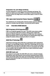
... upgrade kit for users. The system fan rotations per minute (RPM) is not occupied. With this flexibility, ASUS Flex-E makes motherboards suitable for end users. The ASUS MIO audio card is monitored to prevent overheating and damage. This ASUS unique feature enables users to choose their preferred I /O solutions without occupying the Slot 6 in 1U system...
... upgrade kit for users. The system fan rotations per minute (RPM) is not occupied. With this flexibility, ASUS Flex-E makes motherboards suitable for end users. The ASUS MIO audio card is monitored to prevent overheating and damage. This ASUS unique feature enables users to choose their preferred I /O solutions without occupying the Slot 6 in 1U system...
User Manual
Page 35
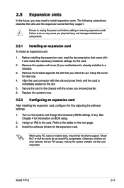
.... 1. Secure the card to install expansion cards. See Chapter 4 for later use . Align the card connector with the slot and press firmly until the card is already installed in a chassis). 3. ASUS P7F-E 2-17 Assign an IRQ to unplug the power cord before adding or removing expansion cards. Remove the system unit cover (if your motherboard is completely seated...
.... 1. Secure the card to install expansion cards. See Chapter 4 for later use . Align the card connector with the slot and press firmly until the card is already installed in a chassis). 3. ASUS P7F-E 2-17 Assign an IRQ to unplug the power cord before adding or removing expansion cards. Remove the system unit cover (if your motherboard is completely seated...
User Manual
Page 36
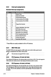
...Express x16 slot (x8 link) The onboard PCI Express x16 slots provides one x8 link to CPU. This slot supports VGA cards and various server class high performance add-on cards. 2.5.6 PCI Express x16 slot (x16 link) The onboard PCI Express x16 slot provides one x16 link or one x8 ... Secondary IDE Channel * These IRQs are usually available for ISA or PCI devices. 2.5.4 MIO PCIE slot The MIO PCIE slot only supports a MIO audio card, which offers great sound quality to x8 link automatically if the slot location 3 is occupied. 2-18 Chapter 2: Hardware information The x16 link switches to ...
...Express x16 slot (x8 link) The onboard PCI Express x16 slots provides one x8 link to CPU. This slot supports VGA cards and various server class high performance add-on cards. 2.5.6 PCI Express x16 slot (x16 link) The onboard PCI Express x16 slot provides one x16 link or one x8 ... Secondary IDE Channel * These IRQs are usually available for ISA or PCI devices. 2.5.4 MIO PCIE slot The MIO PCIE slot only supports a MIO audio card, which offers great sound quality to x8 link automatically if the slot location 3 is occupied. 2-18 Chapter 2: Hardware information The x16 link switches to ...

User Manual
Page 37
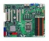
ASUS P7F-E 2-19 Install an optional ASUS PIKE RAID card based on your preferred SAS solution easily. MIO PCIE slot PCIEx16 slot (x16 link) PCI slot PCIEx1 slot PCIEx16 slot (x8 link) PCI slots PIKE Interface The PIKE Interface is for ASUS PIKE RAID card only. 2.5.7 PCI Express x1 slot This slot supports PCI Express cards that comply with the PCI Express specifications. 2.5.8 PCI slots The PCI slot supports cards such as a LAN card, USB card, and other cards that comply with PCI 2.3 specifications. 2.5.9 PIKE slot The PIKE slot allows you to choose and change your needs.
ASUS P7F-E 2-19 Install an optional ASUS PIKE RAID card based on your preferred SAS solution easily. MIO PCIE slot PCIEx16 slot (x16 link) PCI slot PCIEx1 slot PCIEx16 slot (x8 link) PCI slots PIKE Interface The PIKE Interface is for ASUS PIKE RAID card only. 2.5.7 PCI Express x1 slot This slot supports PCI Express cards that comply with the PCI Express specifications. 2.5.8 PCI slots The PCI slot supports cards such as a LAN card, USB card, and other cards that comply with PCI 2.3 specifications. 2.5.9 PIKE slot The PIKE slot allows you to choose and change your needs.

User Manual
Page 38
Align the golden fingers of the RAID card with the PIKE RAID card slot. 3. Ensure that it is completely seated on the motherboard. 2. Insert the RAID card into the PIKE RAID card slot. Locate the PIKE RAID card slot on the PIKE RAID card slot. 2-20 Chapter 2: Hardware information 2.5.10 Installing an ASUS PIKE RAID card Follow the steps below to install an optional ASUS RAID card on your motherboard. 1.
Align the golden fingers of the RAID card with the PIKE RAID card slot. 3. Ensure that it is completely seated on the motherboard. 2. Insert the RAID card into the PIKE RAID card slot. Locate the PIKE RAID card slot on the PIKE RAID card slot. 2-20 Chapter 2: Hardware information 2.5.10 Installing an ASUS PIKE RAID card Follow the steps below to install an optional ASUS RAID card on your motherboard. 1.

User Manual
Page 39
Locate the I Button slot on the motherboard. 2. ASUS P7F-E 2-21 Locate the BMC_FW1 header on the motherboard. 2. You need to install I Button in place. Orient and press the ASMB4 management card in place. Snap the I Button before using PIKE 1078 functions. 2.5.12 Installing ASMB4 management board Follow the steps below to install an optional ASMB4 management board on your motherboard. 1. 2.5.11 Installing i Button Follow the steps below to install an optional i Button on your motherboard. 1.
Locate the I Button slot on the motherboard. 2. ASUS P7F-E 2-21 Locate the BMC_FW1 header on the motherboard. 2. You need to install I Button in place. Orient and press the ASMB4 management card in place. Snap the I Button before using PIKE 1078 functions. 2.5.12 Installing ASMB4 management board Follow the steps below to install an optional ASMB4 management board on your motherboard. 1. 2.5.11 Installing i Button Follow the steps below to install an optional i Button on your motherboard. 1.

User Manual
Page 40
... with the slot and press firmly until the card sits on the motherboard. 2. This slot does not support PCI-E x1 cards. 2-22 Chapter 2: Hardware information 2.5.13 Connect Thermal sensor cable Follow the steps below to connect the thermal sensor cable to the connector. 3. Locate ...the audio slot on the slot completely. Connect the thermal sensor cable to the connector on the motherboard. 2. Place the other end of the thermal sensor cable to the device you would like to monitor temperature. 2.5.14 Installing the audio card 1. Locate the TR1 connector on your...
... with the slot and press firmly until the card sits on the motherboard. 2. This slot does not support PCI-E x1 cards. 2-22 Chapter 2: Hardware information 2.5.13 Connect Thermal sensor cable Follow the steps below to connect the thermal sensor cable to the connector. 3. Locate ...the audio slot on the slot completely. Connect the thermal sensor cable to the connector on the motherboard. 2. Place the other end of the thermal sensor cable to the device you would like to monitor temperature. 2.5.14 Installing the audio card 1. Locate the TR1 connector on your...

User Manual
Page 43
Place the jumper caps on pins 1-2 if you install a PIKE RAID card to the motherboard and want to use the LSI Logic MPT Setup Utility (default). 4. LAN controller setting (3-pin LAN_SW1, LAN_SW2) These jumpers allow you create disk arrays. ASUS P7F-E 2-25 iBTN RAID setting (3-pin IBTN_SEL1) This jumper allows you to select the RAID configuration utility to use when you to activate the Gigabit LAN feature. 5. Set to pins 1-2 to enable or disable the onboard Intel® Intel 82574LGigabit LAN controllers.
Place the jumper caps on pins 1-2 if you install a PIKE RAID card to the motherboard and want to use the LSI Logic MPT Setup Utility (default). 4. LAN controller setting (3-pin LAN_SW1, LAN_SW2) These jumpers allow you create disk arrays. ASUS P7F-E 2-25 iBTN RAID setting (3-pin IBTN_SEL1) This jumper allows you to select the RAID configuration utility to use when you to activate the Gigabit LAN feature. 5. Set to pins 1-2 to enable or disable the onboard Intel® Intel 82574LGigabit LAN controllers.

User Manual
Page 45
... BLINKING Data activity Speed LED Status Description OFF 10 Mbps connection ORANGE 100 Mbps connection GREEN 1 Gbps connection ACT/LINK SPEED LED LED LAN port ASUS P7F-E 2-27 USB 2.0 ports 1 and 2. Video Graphics Adapter port. LAN 2 (RJ-45) port. 2.7 Connectors 2.7.1 Rear panel connectors 1. ...This RJ-45 port functions only when you install ASMB4 management card. 3. These two 4-pin Universal Serial Bus (USB) ports are available for iKVM. Serial (COM1) port. This port is for the LAN port LED ...
... BLINKING Data activity Speed LED Status Description OFF 10 Mbps connection ORANGE 100 Mbps connection GREEN 1 Gbps connection ACT/LINK SPEED LED LED LAN port ASUS P7F-E 2-27 USB 2.0 ports 1 and 2. Video Graphics Adapter port. LAN 2 (RJ-45) port. 2.7 Connectors 2.7.1 Rear panel connectors 1. ...This RJ-45 port functions only when you install ASMB4 management card. 3. These two 4-pin Universal Serial Bus (USB) ports are available for iKVM. Serial (COM1) port. This port is for the LAN port LED ...

User Manual
Page 47
... supports one device. • These connectors function only when you install a PIKE RAID card. • Connect the SAS hard disk drives to the SATA or SAS add-on card. ASUS P7F-E 2-29 SAS connectors (7-pin SAS1, SAS2, SAS3, SAS4; Blue) This motherboard comes with eight (8) Serial Attached SCSI (SAS) connectors, the next-generation storage technology...
... supports one device. • These connectors function only when you install a PIKE RAID card. • Connect the SAS hard disk drives to the SATA or SAS add-on card. ASUS P7F-E 2-29 SAS connectors (7-pin SAS1, SAS2, SAS3, SAS4; Blue) This motherboard comes with eight (8) Serial Attached SCSI (SAS) connectors, the next-generation storage technology...

User Manual
Page 50
Serial General Purpose Input/Output connectors (8-1 pin SGPIO2/3) These connector is used for the LSI MegaRAID and Intel Matrix RAID SATA LED. 8. These connectors functions only when you install an ASUS PIKE SAS RAID card. 2-32 Chapter 2: Hardware information Serial General Purpose Input/Output connector (6-1 pin SGPIO1) This connector is used for the SGPIO peripherals for the SAS chip SGPIO interface that controls the LED pattern generation, device information and general purpose data. 7.
Serial General Purpose Input/Output connectors (8-1 pin SGPIO2/3) These connector is used for the LSI MegaRAID and Intel Matrix RAID SATA LED. 8. These connectors functions only when you install an ASUS PIKE SAS RAID card. 2-32 Chapter 2: Hardware information Serial General Purpose Input/Output connector (6-1 pin SGPIO1) This connector is used for the SGPIO peripherals for the SAS chip SGPIO interface that controls the LED pattern generation, device information and general purpose data. 7.

User Manual
Page 89
...computer cannot receive or transmit data until the computer and applications are fully running. ASUS P7F-E 4-31 Power On By RTC Alarm [Disabled] Allows you to enable or ... Power On By PCIE Devices [Disabled] Allows you to turn on the system through a PCI LAN or modem card. Use the or key to generate a wake event. Power On By External Modems [Disabled] [Disabled] Disables.... Power On By PCI Devices [Disabled] [Disabled] Disables the PME to [Enabled]. This feature requires an ATX power supply that turns the system power on the first try. RTC Alarm Date [15] To set to ...
...computer cannot receive or transmit data until the computer and applications are fully running. ASUS P7F-E 4-31 Power On By RTC Alarm [Disabled] Allows you to enable or ... Power On By PCIE Devices [Disabled] Allows you to turn on the system through a PCI LAN or modem card. Use the or key to generate a wake event. Power On By External Modems [Disabled] [Disabled] Disables.... Power On By PCI Devices [Disabled] [Disabled] Disables the PME to [Enabled]. This feature requires an ATX power supply that turns the system power on the first try. RTC Alarm Date [15] To set to ...

User Manual
Page 145
OK Back The drivers for the RAID card are installed to load any more driver disks? When asked if you install RHEL AS5, when the installation is completed, DO NOT click Reboot. If ... the floppy disk drive, select OK, then press . Yes No 8. mkdir /mnt/driver mount /dev/fd0 /mnt/driver cd /mnt/driver sh replace_ahci.sh reboot ASUS P7F-E 6-15 Insert the Red Hat® Enterprise RAID driver disk to the command-line interface from graphic user interface. 10. Follow the onscreen instructions to...
OK Back The drivers for the RAID card are installed to load any more driver disks? When asked if you install RHEL AS5, when the installation is completed, DO NOT click Reboot. If ... the floppy disk drive, select OK, then press . Yes No 8. mkdir /mnt/driver mount /dev/fd0 /mnt/driver cd /mnt/driver sh replace_ahci.sh reboot ASUS P7F-E 6-15 Insert the Red Hat® Enterprise RAID driver disk to the command-line interface from graphic user interface. 10. Follow the onscreen instructions to...


