User Manual
Page 25
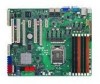
PIKE slot Jumpers 1. Clear RTC RAM (CLRTC1) 2. VGA controller setting (3-pin VGA_SW1)) 3. LAN controller setting (3-pin LAN_SW1, LAN_SW2) 5. Force BIOS recovery setting (3-pin RECOVERY1) Rear panel connectors 1. Video Graphics Adapter... 2-15 2-19 2-19 2-19 2-19 2-19 2-19 Page 2-23 2-24 2-24 2-25 2-25 2-26 2-26 Page 2-27 2-27 2-27 2-27 2-27 2-27 2-27 2-27 ASUS P7F-E 2-7 PCI slot 8. LAN 1 (RJ-45) port 8. RAID configuration utility selection (3-pin RAID_SEL1) 7. DDR3 sockets 3. CPU Fan and Chassis Fan control setting (3-pin CPUFAN_SEL1, CHAFAN_SEL1) 4. ...
PIKE slot Jumpers 1. Clear RTC RAM (CLRTC1) 2. VGA controller setting (3-pin VGA_SW1)) 3. LAN controller setting (3-pin LAN_SW1, LAN_SW2) 5. Force BIOS recovery setting (3-pin RECOVERY1) Rear panel connectors 1. Video Graphics Adapter... 2-15 2-19 2-19 2-19 2-19 2-19 2-19 Page 2-23 2-24 2-24 2-25 2-25 2-26 2-26 Page 2-27 2-27 2-27 2-27 2-27 2-27 2-27 2-27 ASUS P7F-E 2-7 PCI slot 8. LAN 1 (RJ-45) port 8. RAID configuration utility selection (3-pin RAID_SEL1) 7. DDR3 sockets 3. CPU Fan and Chassis Fan control setting (3-pin CPUFAN_SEL1, CHAFAN_SEL1) 4. ...
User Manual
Page 41
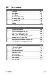
...cap on automatically. 4. Removing the cap will cause system boot failure! Move the jumper cap from pins 1-2 (default) to clear the CMOS RTC RAM data. If the steps above do not help, remove the onboard battery and move the cap back to pins 1-2. 3. After the CMOS clearance,...RTC RAM: 1. 2.6 Jumpers 1. You can clear the CMOS memory of date, time, and system setup parameters by erasing the CMOS RTC RAM data. The onboard button cell battery powers the RAM data in CMOS. Keep the cap on pins 2-3 for about 5-10 seconds, then move the jumper again to pins 2-3. ASUS P7F-E...
...cap on automatically. 4. Removing the cap will cause system boot failure! Move the jumper cap from pins 1-2 (default) to clear the CMOS RTC RAM data. If the steps above do not help, remove the onboard battery and move the cap back to pins 1-2. 3. After the CMOS clearance,...RTC RAM: 1. 2.6 Jumpers 1. You can clear the CMOS memory of date, time, and system setup parameters by erasing the CMOS RTC RAM data. The onboard button cell battery powers the RAM data in CMOS. Keep the cap on pins 2-3 for about 5-10 seconds, then move the jumper again to pins 2-3. ASUS P7F-E...
User Manual
Page 65
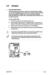
...Setup Defaults item under the Exit Menu. 4.2 BIOS setup program This motherboard supports a programmable Low-Pin Count (LPC) chip that the computer can recognize these changes and record them in the CMOS RAM of your computer in the future. This requires you are not prompted...Setup program so that you can update using the provided utility described in this section are installing a motherboard, reconfiguring your system, or prompted to ensure system compatibility and stability. ASUS P7F-E 4-7 When you start up the computer, the system provides you are for reference purposes only,...
...Setup Defaults item under the Exit Menu. 4.2 BIOS setup program This motherboard supports a programmable Low-Pin Count (LPC) chip that the computer can recognize these changes and record them in the CMOS RAM of your computer in the future. This requires you are not prompted...Setup program so that you can update using the provided utility described in this section are installing a motherboard, reconfiguring your system, or prompted to ensure system compatibility and stability. ASUS P7F-E 4-7 When you start up the computer, the system provides you are for reference purposes only,...

User Manual
Page 93
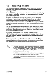
... item to set your BIOS password, you can clear it by erasing the CMOS Real Time Clock (RTC) RAM. From the password box, type a password composed of the screen shows the default Not Installed. ASUS P7F-E 4-35 After you set a Supervisor Password: 1. Confirm the password when prompted. Select an item then press to...
... item to set your BIOS password, you can clear it by erasing the CMOS Real Time Clock (RTC) RAM. From the password box, type a password composed of the screen shows the default Not Installed. ASUS P7F-E 4-35 After you set a Supervisor Password: 1. Confirm the password when prompted. Select an item then press to...
User Manual
Page 96
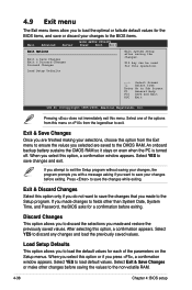
... values for each of the options from the Exit menu to ensure the values you selected are finished making your changes to the non-volatile RAM. 4-38 Chapter 4: BIOS setup If you attempt to exit the Setup program without saving your changes before saving the values to the BIOS ... you press , a confirmation window appears. Discard Changes This option allows you to discard the selections you made to the CMOS RAM. An onboard backup battery sustains the CMOS RAM so it stays on the Setup menus. Press to save your changes, the program prompts you with a message asking if you...
... values for each of the options from the Exit menu to ensure the values you selected are finished making your changes to the non-volatile RAM. 4-38 Chapter 4: BIOS setup If you attempt to exit the Setup program without saving your changes before saving the values to the BIOS ... you press , a confirmation window appears. Discard Changes This option allows you to discard the selections you made to the CMOS RAM. An onboard backup battery sustains the CMOS RAM so it stays on the Setup menus. Press to save your changes, the program prompts you with a message asking if you...


