
Motherboard DIY Troubleshooting Guide
Page 1
P5VDC-MX Motherboard
P5VDC-MX Motherboard

Motherboard DIY Troubleshooting Guide
Page 3
Contents Notices vi Safety information vii About this guide viii P5VDC-MX specifications summary x Chapter 1: Product introduction 1.1 Welcome 1-2 1.2 Package contents 1-2 1.3 Special features 1-2 1.3.1 Product highlights 1-2 1.3.2 Innovative ASUS features 1-4 1.4 Before you proceed 1-5 1.5 Motherboard overview 1-6 1.5.1 Placement direction 1-6 1.5.2 Screw holes 1-6 1.5.3 Motherboard layout 1-7 1.6 Central Processing Unit (CPU 1-8 1.6.1 Installling the CPU 1-8 1.6.2 Installling the CPU heatsink and fan 1-11 1.6.3 Uninstalling the CPU heatsink...
Contents Notices vi Safety information vii About this guide viii P5VDC-MX specifications summary x Chapter 1: Product introduction 1.1 Welcome 1-2 1.2 Package contents 1-2 1.3 Special features 1-2 1.3.1 Product highlights 1-2 1.3.2 Innovative ASUS features 1-4 1.4 Before you proceed 1-5 1.5 Motherboard overview 1-6 1.5.1 Placement direction 1-6 1.5.2 Screw holes 1-6 1.5.3 Motherboard layout 1-7 1.6 Central Processing Unit (CPU 1-8 1.6.1 Installling the CPU 1-8 1.6.2 Installling the CPU heatsink and fan 1-11 1.6.3 Uninstalling the CPU heatsink...

Motherboard DIY Troubleshooting Guide
Page 7
...the product, make sure all power cables are not damaged. If you add a device. • Before connecting or removing signal cables from the motherboard, ensure that all cables are correctly connected and the power cables are unplugged. • Seek professional assistance before using , contact your retailer. Do... company. • If the power supply is set to the correct voltage in your area. Operation safety • Before installing the motherboard and adding devices on it, carefully read all power cables from the existing system before you detect any area where it by yourself. ...
...the product, make sure all power cables are not damaged. If you add a device. • Before connecting or removing signal cables from the motherboard, ensure that all cables are correctly connected and the power cables are unplugged. • Seek professional assistance before using , contact your retailer. Do... company. • If the power supply is set to the correct voltage in your area. Operation safety • Before installing the motherboard and adding devices on it, carefully read all power cables from the existing system before you detect any area where it by yourself. ...

Motherboard DIY Troubleshooting Guide
Page 8
... organized This manual contains the following sources for additional information and for product and software updates. 1. ASUS websites The ASUS website provides updated information on the motherboard. • Chapter 2: BIOS setup This chapter tells how to the ASUS contact information. 2. Refer to change system settings through the BIOS Setup menus. Detailed descriptions of the...
... organized This manual contains the following sources for additional information and for product and software updates. 1. ASUS websites The ASUS website provides updated information on the motherboard. • Chapter 2: BIOS setup This chapter tells how to the ASUS contact information. 2. Refer to change system settings through the BIOS Setup menus. Detailed descriptions of the...

Motherboard DIY Troubleshooting Guide
Page 13
This chapter describes the motherboard features and the new technologies it supports. 1Product introduction ASUS P5VDC-MX 1-1
This chapter describes the motherboard features and the new technologies it supports. 1Product introduction ASUS P5VDC-MX 1-1

Motherboard DIY Troubleshooting Guide
Page 14
... for the Intel® Pentium® 4 processor in the 775-land package. See page 1-8 for the following items. Motherboard ASUS P5VDC-MX motherboard Cables 1 x Serial ATA power cable 1 x Serial ATA signal cable 1 x Ultra DMA 133/100 cables 1 x Floppy disk drive cable Accessories I/O shield A p p l i c a t i o n C D s ASUS motherboard support CD D o c u m e n t a t i o n User guide If any of up to 3.8 GHz. 1.1 Welcome! The...
... for the Intel® Pentium® 4 processor in the 775-land package. See page 1-8 for the following items. Motherboard ASUS P5VDC-MX motherboard Cables 1 x Serial ATA power cable 1 x Serial ATA signal cable 1 x Ultra DMA 133/100 cables 1 x Floppy disk drive cable Accessories I/O shield A p p l i c a t i o n C D s ASUS motherboard support CD D o c u m e n t a t i o n User guide If any of up to 3.8 GHz. 1.1 Welcome! The...

Motherboard DIY Troubleshooting Guide
Page 15
...up to 300 MB/s data transfer rate. See page 1-24, 1-26, 1-31 for four SATA connectors. Serial ATA II technology The motherboard supports the Serial ATA II technology through the Serial ATA interfaces and the VIA VT8251 chipset. AGP 8X support The AGP 8X (AGP 3.0)..., faster memory access and increased productivity. The SATA specification allows for details. ASUS P5VDC-MX 1-3 64-bit CPU support 64-bit computing, the next generation technology to a fast 480 Mbps on USB 2.0. This motherboard provides excellent compatibility and flexibility by supporting either 64-bit or 32-bit architecture...
...up to 300 MB/s data transfer rate. See page 1-24, 1-26, 1-31 for four SATA connectors. Serial ATA II technology The motherboard supports the Serial ATA II technology through the Serial ATA interfaces and the VIA VT8251 chipset. AGP 8X support The AGP 8X (AGP 3.0)..., faster memory access and increased productivity. The SATA specification allows for details. ASUS P5VDC-MX 1-3 64-bit CPU support 64-bit computing, the next generation technology to a fast 480 Mbps on USB 2.0. This motherboard provides excellent compatibility and flexibility by supporting either 64-bit or 32-bit architecture...

Motherboard DIY Troubleshooting Guide
Page 17
...uninstall any component, place it on a grounded antistatic pad or in any motherboard component. The illustration below shows the location of the following precautions before you install motherboard components or change any motherboard settings. • Unplug the power cord from the wall socket before ...to indicate that the system is switched off mode. P5VDC-MX ® P5VDC-MX Onboard LED SB_PWR ON Standby Power OFF Powered Off ASUS P5VDC-MX 1-5 1.4 Before you proceed Take note of the onboard LED. Onboard LED The motherboard comes with the component. • Before you install ...
...uninstall any component, place it on a grounded antistatic pad or in any motherboard component. The illustration below shows the location of the following precautions before you install motherboard components or change any motherboard settings. • Unplug the power cord from the wall socket before ...to indicate that the system is switched off mode. P5VDC-MX ® P5VDC-MX Onboard LED SB_PWR ON Standby Power OFF Powered Off ASUS P5VDC-MX 1-5 1.4 Before you proceed Take note of the onboard LED. Onboard LED The motherboard comes with the component. • Before you install ...

Motherboard DIY Troubleshooting Guide
Page 18
...of the chassis ® P5VDC-MX 1-6 Chapter 1: Product introduction The edge with external ports goes to the rear part of the chassis as indicated in the correct orientation. Do not overtighten the screws! 1.5 Motherboard overview Before you install the motherboard, study the configuration of ...to do so can damage the motherboard. Doing so can cause you physical injury and damage motherboard components. 1.5.1 Placement direction When installing the motherboard, make sure that the motherboard fits into the holes indicated by circles to secure the motherboard to unplug the power cord ...
...of the chassis ® P5VDC-MX 1-6 Chapter 1: Product introduction The edge with external ports goes to the rear part of the chassis as indicated in the correct orientation. Do not overtighten the screws! 1.5 Motherboard overview Before you install the motherboard, study the configuration of ...to do so can damage the motherboard. Doing so can cause you physical injury and damage motherboard components. 1.5.1 Placement direction When installing the motherboard, make sure that the motherboard fits into the holes indicated by circles to secure the motherboard to unplug the power cord ...

Motherboard DIY Troubleshooting Guide
Page 20
... the socket and the socket pins are not bent. ASUS will process Return Merchandise Authorization (RMA) requests only if the motherboard comes with installation instructions for the CPU, fan and heatsink assembly. P5VDC-MX ® P5VDC-MX CPU Socket 775 Before installing the CPU, make sure ...that the socket box is shipment/ transit-related. • Keep the cap after installing the motherboard. Locate the CPU socket on your retailer immediately...
... the socket and the socket pins are not bent. ASUS will process Return Merchandise Authorization (RMA) requests only if the motherboard comes with installation instructions for the CPU, fan and heatsink assembly. P5VDC-MX ® P5VDC-MX CPU Socket 775 Before installing the CPU, make sure ...that the socket box is shipment/ transit-related. • Keep the cap after installing the motherboard. Locate the CPU socket on your retailer immediately...

Motherboard DIY Troubleshooting Guide
Page 22
... an Intel® Pentium® 4 CPU in BIOS before installing a supported operating system. • For more information on Intel® Hyper-Threading Technology • This motherboard supports Intel® Pentium® 4 CPUs in only one correct orientation. The item appears only if you are using any other operating systems, disable the... damaging the CPU! If you installed a CPU that supports Hyper-Threading Technology. 3. To use the Hyper-Threading compiler to prevent bending the connectors on this motherboard: 1. 6. Reboot the computer. 1-10 Chapter 1: Product introduction
... an Intel® Pentium® 4 CPU in BIOS before installing a supported operating system. • For more information on Intel® Hyper-Threading Technology • This motherboard supports Intel® Pentium® 4 CPUs in only one correct orientation. The item appears only if you are using any other operating systems, disable the... damaging the CPU! If you installed a CPU that supports Hyper-Threading Technology. 3. To use the Hyper-Threading compiler to prevent bending the connectors on this motherboard: 1. 6. Reboot the computer. 1-10 Chapter 1: Product introduction

Motherboard DIY Troubleshooting Guide
Page 23
...If you buy a boxed Intel® Pentium® 4 processor, the package includes the CPU fan and heatsink assembly. ASUS P5VDC-MX 1-11 Place the heatsink on the motherboard. 1.6.2 Installling the CPU heatsink and fan The Intel® Pentium® 4/Pentium® D LGA775 processor requires a ...specially designed heatsink and fan assembly to ensure optimum thermal condition and performance. • Install the motherboard to the chassis before you use only Intel®-certified multi-directional heatsink and fan. • Your Intel® Pentium® ...
...If you buy a boxed Intel® Pentium® 4 processor, the package includes the CPU fan and heatsink assembly. ASUS P5VDC-MX 1-11 Place the heatsink on the motherboard. 1.6.2 Installling the CPU heatsink and fan The Intel® Pentium® 4/Pentium® D LGA775 processor requires a ...specially designed heatsink and fan assembly to ensure optimum thermal condition and performance. • Install the motherboard to the chassis before you use only Intel®-certified multi-directional heatsink and fan. • Your Intel® Pentium® ...

Motherboard DIY Troubleshooting Guide
Page 24
CPU_FAN GND CPU FAN PWR CPU FAN IN CPU FAN PWM ® P5VDC-MX CPU fan connector Do not forget to plug this connector. 1-12 Chapter 1: Product introduction Hardware monitoring errors can occur if you fail to connect the CPU fan connector! 2. A A A B B B A P5VDC-MX 3. When the fan and heatsink assembly is in place. Push down two fasteners at a time in a diagonal sequence to secure the heatsink and fan B assembly in place, connect the CPU fan cable to the connector on the motherboard labeled CPU_FAN.
CPU_FAN GND CPU FAN PWR CPU FAN IN CPU FAN PWM ® P5VDC-MX CPU fan connector Do not forget to plug this connector. 1-12 Chapter 1: Product introduction Hardware monitoring errors can occur if you fail to connect the CPU fan connector! 2. A A A B B B A P5VDC-MX 3. When the fan and heatsink assembly is in place. Push down two fasteners at a time in a diagonal sequence to secure the heatsink and fan B assembly in place, connect the CPU fan cable to the connector on the motherboard labeled CPU_FAN.

Motherboard DIY Troubleshooting Guide
Page 25
Disconnect the CPU fan cable from the A A motherboard. 1.6.3 Uninstalling the CPU heatsink and fan To uninstall the CPU heatsink and fan: 1. B A B B A ASUS P5VDC-MX 1-13 Pull up two fasteners at a time in a diagonal sequence to disengage the heatsink B and fan assembly from the connector on the motherboard labeled CPU_FAN. 2. Rotate each fastener counterclockwise. 3.
Disconnect the CPU fan cable from the A A motherboard. 1.6.3 Uninstalling the CPU heatsink and fan To uninstall the CPU heatsink and fan: 1. B A B B A ASUS P5VDC-MX 1-13 Pull up two fasteners at a time in a diagonal sequence to disengage the heatsink B and fan assembly from the connector on the motherboard labeled CPU_FAN. 2. Rotate each fastener counterclockwise. 3.

Motherboard DIY Troubleshooting Guide
Page 26
Rotate each fastener clockwise to reset the orientation. The narrow end of the groove should point outward after resetting. (The photo shows the groove shaded for emphasis.) Narrow end of the groove 1-14 Chapter 1: Product introduction 4. Remove the heatsink and fan assembly from the motherboard. 5.
Rotate each fastener clockwise to reset the orientation. The narrow end of the groove should point outward after resetting. (The photo shows the groove shaded for emphasis.) Narrow end of the groove 1-14 Chapter 1: Product introduction 4. Remove the heatsink and fan assembly from the motherboard. 5.

Motherboard DIY Troubleshooting Guide
Page 27
1.7 System memory 1.7.1 Overview The motherboard comes with two 240-pin Double Data Rate (DDR2) and two 184-pin DDR Dual Inline Memory Modules (DIMM) sockets. DDR2 DIMMS are notched differently ...-ECC DDR/DDR2 DIMMs into the DIMM sockets. ASUS P5VDC-MX 1-15 The following figure illustrates the location of the sockets: Color Blue Yellow Sockets DDR_1 and DDR_2 DDR2_1 and DDR2_2 P5VDC-MX DDR2_1 DDR2_2 DDR_1 DDR_2 ® P5VDC-MX DDR DIMM sockets • To prevent damage to the motherboard, d o n o t u s e D D R a n d DDR2 memory simultaneously. • Due to prevent installation...
1.7 System memory 1.7.1 Overview The motherboard comes with two 240-pin Double Data Rate (DDR2) and two 184-pin DDR Dual Inline Memory Modules (DIMM) sockets. DDR2 DIMMS are notched differently ...-ECC DDR/DDR2 DIMMs into the DIMM sockets. ASUS P5VDC-MX 1-15 The following figure illustrates the location of the sockets: Color Blue Yellow Sockets DDR_1 and DDR_2 DDR2_1 and DDR2_2 P5VDC-MX DDR2_1 DDR2_2 DDR_1 DDR_2 ® P5VDC-MX DDR DIMM sockets • To prevent damage to the motherboard, d o n o t u s e D D R a n d DDR2 memory simultaneously. • Due to prevent installation...

Motherboard DIY Troubleshooting Guide
Page 28
... of modules inserted into both of the y e l l o w slots. B - Double-sided 1-16 Chapter 1: Product introduction 1.7.3 DDR Qualified Vendors List Visit the ASUS website (www.asus.com) for the latest DDR DIMM modules for this motherboard. Single-sided D S - S S - supports one module inserted in any y e l l o w slot. DDR2-533 Qualified Vendors List Size 256MB 512MB 1024MB 512MB...
... of modules inserted into both of the y e l l o w slots. B - Double-sided 1-16 Chapter 1: Product introduction 1.7.3 DDR Qualified Vendors List Visit the ASUS website (www.asus.com) for the latest DDR DIMM modules for this motherboard. Single-sided D S - S S - supports one module inserted in any y e l l o w slot. DDR2-533 Qualified Vendors List Size 256MB 512MB 1024MB 512MB...

Motherboard DIY Troubleshooting Guide
Page 30
... force a DIMM into the socket until the retaining clips snap back in only one direction. 1.7.4 Installing a DDR DIMM(blue slots) Make sure to both the motherboard and the components. 1. Align a DIMM on the socket such that it flips out with extra force. 2. Locked Retaining Clip 1.7.5 Removing a DDR DIMM Follow these steps...
... force a DIMM into the socket until the retaining clips snap back in only one direction. 1.7.4 Installing a DDR DIMM(blue slots) Make sure to both the motherboard and the components. 1. Align a DIMM on the socket such that it flips out with extra force. 2. Locked Retaining Clip 1.7.5 Removing a DDR DIMM Follow these steps...

Motherboard DIY Troubleshooting Guide
Page 31
... extra force. 2. Simultaneously press the retaining clips outward to both the motherboard and the components. Firmly insert the DIMM into a socket to avoid damaging the DIMM. • The DDR2 DIMM sockets do so can cause severe damage to unlock the DIMM. Remove the DIMM from the socket. 2 1 DDR2 DIMM notch ASUS P5VDC-MX 1-19
... extra force. 2. Simultaneously press the retaining clips outward to both the motherboard and the components. Firmly insert the DIMM into a socket to avoid damaging the DIMM. • The DDR2 DIMM sockets do so can cause severe damage to unlock the DIMM. Remove the DIMM from the socket. 2 1 DDR2 DIMM notch ASUS P5VDC-MX 1-19
Motherboard DIY Troubleshooting Guide
Page 32
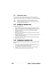
The following sub-sections describe the slots and the expansion cards that you physical injury and damage motherboard components. 1.8.1 Installing an expansion card To install an expansion card: 1. Before installing the expansion card, read the documentation that came with it by adjusting the ... setup. 2. Refer to install expansion cards. Failure to do so may need to the tables on the slot. 5. Remove the system unit cover (if your motherboard is completely seated on the next page. 3.
The following sub-sections describe the slots and the expansion cards that you physical injury and damage motherboard components. 1.8.1 Installing an expansion card To install an expansion card: 1. Before installing the expansion card, read the documentation that came with it by adjusting the ... setup. 2. Refer to install expansion cards. Failure to do so may need to the tables on the slot. 5. Remove the system unit cover (if your motherboard is completely seated on the next page. 3.


