
Motherboard Installation Guide
Page 1
P5RD2-VM Motherboard
P5RD2-VM Motherboard

Motherboard Installation Guide
Page 3
Contents Notices vi Safety information vii About this guide viii Typography ix P5RD2-VM specifications summary x Chapter 1: Product introduction 1.1 Welcome 1-2 1.2 Package contents 1-2 1.3 Special features 1-2 1.3.1 Product highlights 1-2 1.3.2 Innovative ASUS features 1-4 1.4 Before you proceed 1-5 1.5 Motherboard overview 1-6 1.5.1 Placement direction 1-6 1.5.2 Screw holes 1-6 1.5.3 Motherboard layout 1-7 1.6 Central Processing Unit (CPU 1-8 1.6.1 Installling the CPU 1-8 1.6.2 Installling the CPU heatsink and fan 1-11...
Contents Notices vi Safety information vii About this guide viii Typography ix P5RD2-VM specifications summary x Chapter 1: Product introduction 1.1 Welcome 1-2 1.2 Package contents 1-2 1.3 Special features 1-2 1.3.1 Product highlights 1-2 1.3.2 Innovative ASUS features 1-4 1.4 Before you proceed 1-5 1.5 Motherboard overview 1-6 1.5.1 Placement direction 1-6 1.5.2 Screw holes 1-6 1.5.3 Motherboard layout 1-7 1.6 Central Processing Unit (CPU 1-8 1.6.1 Installling the CPU 1-8 1.6.2 Installling the CPU heatsink and fan 1-11...

Motherboard Installation Guide
Page 7
... power cables for disposal of electronic products. Contact a qualified service technician or your retailer. Operation safety • Before installing the motherboard and adding devices on a stable surface. • If you are not damaged. Check local regulations for the devices are unplugged ... assistance before using , contact your dealer immediately. • To avoid short circuits, keep paper clips, screws, and staples away from the motherboard, ensure that all the manuals that came with the product, contact a qualified service technician or your retailer. If you add a device. ...
... power cables for disposal of electronic products. Contact a qualified service technician or your retailer. Operation safety • Before installing the motherboard and adding devices on a stable surface. • If you are not damaged. Check local regulations for the devices are unplugged ... assistance before using , contact your dealer immediately. • To avoid short circuits, keep paper clips, screws, and staples away from the motherboard, ensure that all the manuals that came with the product, contact a qualified service technician or your retailer. If you add a device. ...

Motherboard Installation Guide
Page 8
.... This chapter also lists the hardware setup procedures that you need when installing and configuring the motherboard. It includes description of the standard package. ASUS websites The ASUS website provides updated information on the motherboard. • Chapter 2: BIOS setup This chapter tells how to perform when installing system components. Optional documentation Your...
.... This chapter also lists the hardware setup procedures that you need when installing and configuring the motherboard. It includes description of the standard package. ASUS websites The ASUS website provides updated information on the motherboard. • Chapter 2: BIOS setup This chapter tells how to perform when installing system components. Optional documentation Your...

Motherboard Installation Guide
Page 13
This chapter describes the motherboard features and the new technologies it supports. 1Product introduction ASUS P5RD2-VM 1-1
This chapter describes the motherboard features and the new technologies it supports. 1Product introduction ASUS P5RD2-VM 1-1

Motherboard Installation Guide
Page 14
... with the list below. 1.2 Package contents Check your retailer. 1.3 Special features 1.3.1 Product highlights Latest processor technology The motherboard comes with a 775-pin surface mount Land Grid Array (LGA) socket designed for the following items. Motherboard ASUS P5RD2-VM motherboard Cables 1 x 2-in the long line of the above items is fully compatible with Intel® PCG 04B...
... with the list below. 1.2 Package contents Check your retailer. 1.3 Special features 1.3.1 Product highlights Latest processor technology The motherboard comes with a 775-pin surface mount Land Grid Array (LGA) socket designed for the following items. Motherboard ASUS P5RD2-VM motherboard Cables 1 x 2-in the long line of the above items is fully compatible with Intel® PCG 04B...

Motherboard Installation Guide
Page 15
... current Serial ATA products. This high speed interface is software compatible with the ADI AD1986A audio CODEC that speeds up the PCI bus. ASUS P5RD2-VM 1-3 Serial ATA 3Gb/s technology The motherboard supports the next-generation Serial ATA 3Gb/s technology through the Serial ATA interfaces and the ULI M1575 chipset. PCI Express features point...
... current Serial ATA products. This high speed interface is software compatible with the ADI AD1986A audio CODEC that speeds up the PCI bus. ASUS P5RD2-VM 1-3 Serial ATA 3Gb/s technology The motherboard supports the next-generation Serial ATA 3Gb/s technology through the Serial ATA interfaces and the ULI M1575 chipset. PCI Express features point...

Motherboard Installation Guide
Page 16
... eliminates the need to use a DOS-based utility or boot from the support CD in the motherboard allows you can easily update the system BIOS even before loading the operating system. ASUS MyLogo™ This new feature present in case when the BIOS codes and data are corrupted. ...See details on page 2-33. 1.3.2 Innovative ASUS features ASUS Q-Fan technology The ASUS Q-Fan technology smartly adjusts the CPU fan speed according to the system loading to restore the original BIOS data from a floppy...
... eliminates the need to use a DOS-based utility or boot from the support CD in the motherboard allows you can easily update the system BIOS even before loading the operating system. ASUS MyLogo™ This new feature present in case when the BIOS codes and data are corrupted. ...See details on page 2-33. 1.3.2 Innovative ASUS features ASUS Q-Fan technology The ASUS Q-Fan technology smartly adjusts the CPU fan speed according to the system loading to restore the original BIOS data from a floppy...

Motherboard Installation Guide
Page 17
... Unplug the power cord from the power supply. 1.4 Before you proceed Take note of the onboard LED. Onboard LED The motherboard comes with the component. • Before you should shut down the system and unplug the power cable before handling components to ...soft-off mode. P5RD2-VM ® P5RD2-VM Onboard LED SB_PWR ON Standby Power OFF Powered Off ASUS P5RD2-VM 1-5 This is a reminder that the system is detached from the wall socket before touching any component. • Use a grounded wrist strap or touch a safely grounded object or to the motherboard, peripherals, and/...
... Unplug the power cord from the power supply. 1.4 Before you proceed Take note of the onboard LED. Onboard LED The motherboard comes with the component. • Before you should shut down the system and unplug the power cable before handling components to ...soft-off mode. P5RD2-VM ® P5RD2-VM Onboard LED SB_PWR ON Standby Power OFF Powered Off ASUS P5RD2-VM 1-5 This is a reminder that the system is detached from the wall socket before touching any component. • Use a grounded wrist strap or touch a safely grounded object or to the motherboard, peripherals, and/...

Motherboard Installation Guide
Page 18
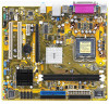
...not overtighten the screws! Make sure to do so can damage the motherboard. Doing so can cause you place it . 1.5 Motherboard overview Before you install the motherboard, study the configuration of your chassis to ensure that you...motherboard components. 1.5.1 Placement direction When installing the motherboard, make sure that the motherboard fits into it into the holes indicated by circles to secure the motherboard to the chassis. Failure to unplug the power cord before installing or removing the motherboard. Place this side towards the rear of the chassis P5RD2-VM...
...not overtighten the screws! Make sure to do so can damage the motherboard. Doing so can cause you place it . 1.5 Motherboard overview Before you install the motherboard, study the configuration of your chassis to ensure that you...motherboard components. 1.5.1 Placement direction When installing the motherboard, make sure that the motherboard fits into it into the holes indicated by circles to secure the motherboard to the chassis. Failure to unplug the power cord before installing or removing the motherboard. Place this side towards the rear of the chassis P5RD2-VM...

Motherboard Installation Guide
Page 20
...the CPU documentation, follow the latter. • Upon purchase of the motherboard, make sure that the PnP cap is on the motherboard. ASUS will process Return Merchandise Authorization (RMA) requests only if the motherboard comes with the cap on your retailer immediately if the PnP cap is ... does not cover damage to the PnP cap/socket pins/motherboard components. ASUS will shoulder the cost of repair only if the damage is shipment/ transit-related. • Keep the cap after installing the motherboard. P5RD2-VM ® P5RD2-VM CPU Socket 775 Before installing the CPU, make sure that...
...the CPU documentation, follow the latter. • Upon purchase of the motherboard, make sure that the PnP cap is on the motherboard. ASUS will process Return Merchandise Authorization (RMA) requests only if the motherboard comes with the cap on your retailer immediately if the PnP cap is ... does not cover damage to the PnP cap/socket pins/motherboard components. ASUS will shoulder the cost of repair only if the damage is shipment/ transit-related. • Keep the cap after installing the motherboard. P5RD2-VM ® P5RD2-VM CPU Socket 775 Before installing the CPU, make sure that...

Motherboard Installation Guide
Page 22
6. DO NOT force the CPU into the retention tab. Refer to prevent bending the connectors on these CPU features. 1-10 Chapter 1: Product introduction The motherboard supports Intel® Pentium® D or Intel® Pentium® 4 LGA775 processors with the Intel® Enhanced Memory 64 Technology (EM64T), Enhanced Intel SpeedStep® ...
6. DO NOT force the CPU into the retention tab. Refer to prevent bending the connectors on these CPU features. 1-10 Chapter 1: Product introduction The motherboard supports Intel® Pentium® D or Intel® Pentium® 4 LGA775 processors with the Intel® Enhanced Memory 64 Technology (EM64T), Enhanced Intel SpeedStep® ...

Motherboard Installation Guide
Page 23
... and requires no tool to the chassis before you install the heatsink and fan assembly. Place the heatsink on the motherboard. To install the CPU heatsink and fan: 1. ASUS P5RD2-VM 1-11 Fastener Motherboard hole Make sure each fastener is properly applied to the CPU heatsink or CPU before you install the CPU fan and... fan The Intel® Pentium® 4 LGA775 processor requires a specially designed heatsink and fan assembly to ensure optimum thermal condition and performance. • Install the motherboard to install.
... and requires no tool to the chassis before you install the heatsink and fan assembly. Place the heatsink on the motherboard. To install the CPU heatsink and fan: 1. ASUS P5RD2-VM 1-11 Fastener Motherboard hole Make sure each fastener is properly applied to the CPU heatsink or CPU before you install the CPU fan and... fan The Intel® Pentium® 4 LGA775 processor requires a specially designed heatsink and fan assembly to ensure optimum thermal condition and performance. • Install the motherboard to install.

Motherboard Installation Guide
Page 24
Hardware monitoring errors can occur if you fail to connect the CPU fan connector! A A A B B B A 3. P5RD2-VM ® CPU_FAN CPU FAN PWM CPU FAN IN CPU FAN PWR GND P5RD2-VM CPU Fan Connector Do not forget to plug this connector. 1-12 Chapter 1: Product introduction When the fan and heatsink assembly is in place. Push down two fasteners at a time in a diagonal sequence to secure the heatsink and fan B assembly in place, connect the CPU fan cable to the connector on the motherboard labeled CPU_FAN. 2.
Hardware monitoring errors can occur if you fail to connect the CPU fan connector! A A A B B B A 3. P5RD2-VM ® CPU_FAN CPU FAN PWM CPU FAN IN CPU FAN PWR GND P5RD2-VM CPU Fan Connector Do not forget to plug this connector. 1-12 Chapter 1: Product introduction When the fan and heatsink assembly is in place. Push down two fasteners at a time in a diagonal sequence to secure the heatsink and fan B assembly in place, connect the CPU fan cable to the connector on the motherboard labeled CPU_FAN. 2.

Motherboard Installation Guide
Page 25
1.6.3 Uninstalling the CPU heatsink and fan To uninstall the CPU heatsink and fan: 1. B A B B A ASUS P5RD2-VM 1-13 Disconnect the CPU fan cable from the A A motherboard. Rotate each fastener counterclockwise. 3. Pull up two fasteners at a time in a diagonal sequence to disengage the heatsink B and fan assembly from the connector on the motherboard. 2.
1.6.3 Uninstalling the CPU heatsink and fan To uninstall the CPU heatsink and fan: 1. B A B B A ASUS P5RD2-VM 1-13 Disconnect the CPU fan cable from the A A motherboard. Rotate each fastener counterclockwise. 3. Pull up two fasteners at a time in a diagonal sequence to disengage the heatsink B and fan assembly from the connector on the motherboard. 2.

Motherboard Installation Guide
Page 26
The narrow end of the groove should point outward after resetting. (The photo shows the groove shaded for emphasis.) Narrow end of the groove 1-14 Chapter 1: Product introduction 4. Rotate each fastener clockwise to reset the orientation. Remove the heatsink and fan assembly from the motherboard. 5.
The narrow end of the groove should point outward after resetting. (The photo shows the groove shaded for emphasis.) Narrow end of the groove 1-14 Chapter 1: Product introduction 4. Rotate each fastener clockwise to reset the orientation. Remove the heatsink and fan assembly from the motherboard. 5.

Motherboard Installation Guide
Page 27
.... DDR2 DIMMs are notched differently to prevent installation on the next page for details. • This motherboard does not support memory modules made up of the sockets: P5RD2-VM ® P5RD2-VM 240-pin DDR DIMM Sockets 1.7.2 Memory configurations You may install 256 MB, 512 MB, and 1... sockets. The following figure illustrates the location of 128 Mb chips or double sided x16 memory modules. DIMM1 DIMM2 ASUS P5RD2-VM 1-15 1.7 System memory 1.7.1 Overview The motherboard comes with the same CAS latency. A DDR2 module has the same physical dimensions as a DDR DIMM but has a ...
.... DDR2 DIMMs are notched differently to prevent installation on the next page for details. • This motherboard does not support memory modules made up of the sockets: P5RD2-VM ® P5RD2-VM 240-pin DDR DIMM Sockets 1.7.2 Memory configurations You may install 256 MB, 512 MB, and 1... sockets. The following figure illustrates the location of 128 Mb chips or double sided x16 memory modules. DIMM1 DIMM2 ASUS P5RD2-VM 1-15 1.7 System memory 1.7.1 Overview The motherboard comes with the same CAS latency. A DDR2 module has the same physical dimensions as a DDR DIMM but has a ...

Motherboard Installation Guide
Page 28
com) for the latest DDR2 DIMM modules for use with this motherboard. DDR2 667 Qualified Vendors List Size 512MB 1024MB 512MB 256MB 256MB 256MB 512MB 256MB 512MB 256MB 512MB 512MB 024MB 512MB 1024MB 256MB 512MB 1024MB 1024MB ... DIMM2 (black) Populated Populated 1.7.3 DDR Qualified Vendors List The following table lists the memory modules that have been tested and qualified for this motherboard. Visit the ASUS website (www.asus. Recommended memory configurations Mode One DIMM Two DIMMs DIMM1 (black) -
com) for the latest DDR2 DIMM modules for use with this motherboard. DDR2 667 Qualified Vendors List Size 512MB 1024MB 512MB 256MB 256MB 256MB 512MB 256MB 512MB 256MB 512MB 512MB 024MB 512MB 1024MB 256MB 512MB 1024MB 1024MB ... DIMM2 (black) Populated Populated 1.7.3 DDR Qualified Vendors List The following table lists the memory modules that have been tested and qualified for this motherboard. Visit the ASUS website (www.asus. Recommended memory configurations Mode One DIMM Two DIMMs DIMM1 (black) -

Motherboard Installation Guide
Page 30
... the DIMM is properly seated. Firmly insert the DIMM into a socket to avoid damaging the DIMM. 3. Simultaneously press the retaining clips outward to both the motherboard and the components. 1. Align a DIMM on the socket such that the notch on the DIMM matches the break on the socket. 1 2 DDR DIMM notch 1 Unlocked...
... the DIMM is properly seated. Firmly insert the DIMM into a socket to avoid damaging the DIMM. 3. Simultaneously press the retaining clips outward to both the motherboard and the components. 1. Align a DIMM on the socket such that the notch on the DIMM matches the break on the socket. 1 2 DDR DIMM notch 1 Unlocked...

Motherboard Installation Guide
Page 31
...installing the expansion card, configure it and make the necessary hardware settings for the expansion card. Turn on the slot. 5. ASUS P5RD2-VM 1-19 Align the card connector with the screw you intend to install expansion cards. Secure the card to unplug the power cord before ...card. The following sub-sections describe the slots and the expansion cards that you removed earlier. 6. Remove the system unit cover (if your motherboard is completely seated on the system and change the necessary BIOS settings, if any. Keep the screw for information on the next page. ...
...installing the expansion card, configure it and make the necessary hardware settings for the expansion card. Turn on the slot. 5. ASUS P5RD2-VM 1-19 Align the card connector with the screw you intend to install expansion cards. Secure the card to unplug the power cord before ...card. The following sub-sections describe the slots and the expansion cards that you removed earlier. 6. Remove the system unit cover (if your motherboard is completely seated on the system and change the necessary BIOS settings, if any. Keep the screw for information on the next page. ...


