
Motherboard Installation Guide
Page 3
... ix P5RD2-VM specifications summary x Chapter 1: Product introduction 1.1 Welcome 1-2 1.2 Package contents 1-2 1.3 Special features 1-2 1.3.1 Product highlights 1-2 1.3.2 Innovative ASUS features 1-4 1.4 Before you proceed 1-5 1.5 Motherboard overview 1-6 1.5.1 Placement direction 1-6 1.5.2 Screw holes 1-6 1.5.3 Motherboard layout 1-7 1.6 Central Processing Unit (CPU 1-8 1.6.1 Installling the CPU 1-8 1.6.2 Installling the CPU heatsink and fan 1-11 1.6.3 Uninstalling the CPU heatsink and fan 1-13 1.7 System memory...
... ix P5RD2-VM specifications summary x Chapter 1: Product introduction 1.1 Welcome 1-2 1.2 Package contents 1-2 1.3 Special features 1-2 1.3.1 Product highlights 1-2 1.3.2 Innovative ASUS features 1-4 1.4 Before you proceed 1-5 1.5 Motherboard overview 1-6 1.5.1 Placement direction 1-6 1.5.2 Screw holes 1-6 1.5.3 Motherboard layout 1-7 1.6 Central Processing Unit (CPU 1-8 1.6.1 Installling the CPU 1-8 1.6.2 Installling the CPU heatsink and fan 1-11 1.6.3 Uninstalling the CPU heatsink and fan 1-13 1.7 System memory...

Motherboard Installation Guide
Page 15
... high speed interface is software compatible with 533/800/1066 MHz front side bus (FSB), single channel DDR 2 memory, one PCI Express x1 slots, and a PCI Express x16 slot for a processor in packets. ASUS P5RD2-VM 1-3 ATI Radeon® XPRESS 200/ULI M1575 chipset The ATI Radeon® XPRESS 200 Northbridge and the ULI...
... high speed interface is software compatible with 533/800/1066 MHz front side bus (FSB), single channel DDR 2 memory, one PCI Express x1 slots, and a PCI Express x16 slot for a processor in packets. ASUS P5RD2-VM 1-3 ATI Radeon® XPRESS 200/ULI M1575 chipset The ATI Radeon® XPRESS 200 Northbridge and the ULI...

Motherboard Installation Guide
Page 22
...;ts in only one correct orientation. The motherboard supports Intel® Pentium® D or Intel® Pentium® 4 LGA775 processors with the Intel® Enhanced Memory 64 Technology (EM64T), Enhanced Intel SpeedStep® Technology (EIST), and Hyper-Threading Technology. 6. DO NOT force the CPU into the retention tab. Refer to prevent...
...;ts in only one correct orientation. The motherboard supports Intel® Pentium® D or Intel® Pentium® 4 LGA775 processors with the Intel® Enhanced Memory 64 Technology (EM64T), Enhanced Intel SpeedStep® Technology (EIST), and Hyper-Threading Technology. 6. DO NOT force the CPU into the retention tab. Refer to prevent...

Motherboard Installation Guide
Page 27
...figurations in this section. • Always install DIMMs with two 240-pin Double Data Rate 2 (DDR2) Dual Inline Memory Modules (DIMM) sockets. DIMM1 DIMM2 ASUS P5RD2-VM 1-15 DDR2 DIMMs are notched differently to the 184-pin DDR DIMM. Refer to the DDR2 Qualified Vendors List on a DDR DIMM socket. ...
...figurations in this section. • Always install DIMMs with two 240-pin Double Data Rate 2 (DDR2) Dual Inline Memory Modules (DIMM) sockets. DIMM1 DIMM2 ASUS P5RD2-VM 1-15 DDR2 DIMMs are notched differently to the 184-pin DDR DIMM. Refer to the DDR2 Qualified Vendors List on a DDR DIMM socket. ...

Motherboard Installation Guide
Page 28
...with this motherboard. Populated Sockets DIMM2 (black) Populated Populated 1.7.3 DDR Qualified Vendors List The following table lists the memory modules that have been tested and qualified for this motherboard. DDR2 667 Qualified Vendors List Size 512MB 1024MB... N/A N/A DS BL12864AA664.16FA V V N/A N/A DS BL6464AL664.16FB V V N/A N/A DS BL12864AL664.16FA V V N/A N/A SS KLCC28F-A8EB5 V V N/A N/A SS M20EL5G3H3160B1C0Z V V 1-16 Chapter 1: Product introduction Visit the ASUS website (www.asus. Recommended memory configurations Mode One DIMM Two DIMMs DIMM1 (black) -
...with this motherboard. Populated Sockets DIMM2 (black) Populated Populated 1.7.3 DDR Qualified Vendors List The following table lists the memory modules that have been tested and qualified for this motherboard. DDR2 667 Qualified Vendors List Size 512MB 1024MB... N/A N/A DS BL12864AA664.16FA V V N/A N/A DS BL6464AL664.16FB V V N/A N/A DS BL12864AL664.16FA V V N/A N/A SS KLCC28F-A8EB5 V V N/A N/A SS M20EL5G3H3160B1C0Z V V 1-16 Chapter 1: Product introduction Visit the ASUS website (www.asus. Recommended memory configurations Mode One DIMM Two DIMMs DIMM1 (black) -

Motherboard Installation Guide
Page 29
...figuration B : Supports one pair of modules inserted into eithor the blue slots or the black slots as one pair of Dual-channel memory configuration ASUS P5RD2-VM 1-17 DDR2 533 Qualified Vendors List Size 256MB 512MB 1024MB 512MB 256MB 512MB 1024MB 256MB Vendor Mode KINGSTON E5116AB-5C-E KINGSTON HY5PS56821F-C4 KINGSTON...
...figuration B : Supports one pair of modules inserted into eithor the blue slots or the black slots as one pair of Dual-channel memory configuration ASUS P5RD2-VM 1-17 DDR2 533 Qualified Vendors List Size 256MB 512MB 1024MB 512MB 256MB 512MB 1024MB 256MB Vendor Mode KINGSTON E5116AB-5C-E KINGSTON HY5PS56821F-C4 KINGSTON...

Motherboard Installation Guide
Page 34
... clearing the RTC RAM, never remove the cap on pins 2-3 for about 5~10 seconds, then move the cap back to re-enter data. P5RD2-VM ® CLRTC 12 23 P5RD2-VM Clear RTC RAM Normal (Default) Clear CMOS You do not need to clear the RTC when the system hangs due to pins 2-3. Turn... the power cord. 2. Plug the power cord and turn ON the computer. 6. Hold down and reboot the system so the BIOS can clear the CMOS memory of date, time, and system setup parameters by erasing the CMOS RTC RAM data. Removing the cap will cause system boot failure! Keep the cap...
... clearing the RTC RAM, never remove the cap on pins 2-3 for about 5~10 seconds, then move the cap back to re-enter data. P5RD2-VM ® CLRTC 12 23 P5RD2-VM Clear RTC RAM Normal (Default) Clear CMOS You do not need to clear the RTC when the system hangs due to pins 2-3. Turn... the power cord. 2. Plug the power cord and turn ON the computer. 6. Hold down and reboot the system so the BIOS can clear the CMOS memory of date, time, and system setup parameters by erasing the CMOS RTC RAM data. Removing the cap will cause system boot failure! Keep the cap...

Motherboard Installation Guide
Page 59
...2.2.6 Configuration fields These fields show the values for the menu items. If an item is highlighted when selected. Configure DRAM Timing by SPD Memory Acceleration Mode DRAM Idle Timer DRAm Refresh Rate [Enabled] [Auto] [Auto] [Auto] Graphic Adapter Priority Graphics Aperture Size Spread Spectrum [AGP/PCI... Item +- Refer to "2.2.7 Pop-up window." 2.2.7 Pop-up window Select a menu item then press to display a pop-up window Scroll bar ASUS P5RD2-VM 2-13 Press the Up/Down arrow keys or / keys to display the other items (Advanced, Power, Boot, and Exit) on the menu bar...
...2.2.6 Configuration fields These fields show the values for the menu items. If an item is highlighted when selected. Configure DRAM Timing by SPD Memory Acceleration Mode DRAM Idle Timer DRAm Refresh Rate [Enabled] [Auto] [Auto] [Auto] Graphic Adapter Priority Graphics Aperture Size Spread Spectrum [AGP/PCI... Item +- Refer to "2.2.7 Pop-up window." 2.2.7 Pop-up window Select a menu item then press to display a pop-up window Scroll bar ASUS P5RD2-VM 2-13 Press the Up/Down arrow keys or / keys to display the other items (Advanced, Power, Boot, and Exit) on the menu bar...

Motherboard Installation Guide
Page 62
... or disables 32-bit data transfer. AMIBIOS Version : 0104 Build Date : 11/11/05 Processor Type : Genuine Intel(R) CPU 3.80GHz Speed : 3000 MHz Count : 1 System Memory Size : 192MB AMI BIOS Displays the auto-detected BIOS information Processor Displays the auto-detected CPU specification System...
... or disables 32-bit data transfer. AMIBIOS Version : 0104 Build Date : 11/11/05 Processor Type : Genuine Intel(R) CPU 3.80GHz Speed : 3000 MHz Count : 1 System Memory Size : 192MB AMI BIOS Displays the auto-detected BIOS information Processor Displays the auto-detected CPU specification System...

Motherboard Installation Guide
Page 65
... Displays the frequency sent by the BIOS. Refer to achieve desired CPU internal frequency. 2.4.2 JumperFree Configuration Configure System Frequency/Voltage Overclocking Memory Clock Mode OverClock Memory Clock [Auto] [Manual] [275MHz] Select the target CPU frequency, and the relevant parameters will be stable. loads the optimal settings for.../CPU External Frequency Synchronization Front Side Bus FSB 1066 FSB 800 FSB 533 CPU External Frequency 266 MHz 200 MHz 133 MHz ASUS P5RD2-VM 2-19 Frequencies higher than CPU manufacturer recommends are not guaranteed to [Manual].
... Displays the frequency sent by the BIOS. Refer to achieve desired CPU internal frequency. 2.4.2 JumperFree Configuration Configure System Frequency/Voltage Overclocking Memory Clock Mode OverClock Memory Clock [Auto] [Manual] [275MHz] Select the target CPU frequency, and the relevant parameters will be stable. loads the optimal settings for.../CPU External Frequency Synchronization Front Side Bus FSB 1066 FSB 800 FSB 533 CPU External Frequency 266 MHz 200 MHz 133 MHz ASUS P5RD2-VM 2-19 Frequencies higher than CPU manufacturer recommends are not guaranteed to [Manual].

Motherboard Installation Guide
Page 66
Setting a very high memory voltage may damage the memory module(s)! OverClock Memory Clock [XXX] Allows you to synchronize the Memory frequency with the CPU frequency. The values range from 100 to set the Memory frequency. You can also type the desired CPU frequency using the numeric keypad. Use the and keys to the DDR2 documentation before adjusting the memory voltage. Configuration options: [Auto] [Manual] Refer to adjust the Memory frequency. Memory Clock Mode [Manual] Allows you to 400. 2-20 Chapter 2: BIOS setup
Setting a very high memory voltage may damage the memory module(s)! OverClock Memory Clock [XXX] Allows you to synchronize the Memory frequency with the CPU frequency. The values range from 100 to set the Memory frequency. You can also type the desired CPU frequency using the numeric keypad. Use the and keys to the DDR2 documentation before adjusting the memory voltage. Configuration options: [Auto] [Manual] Refer to adjust the Memory frequency. Memory Clock Mode [Manual] Allows you to 400. 2-20 Chapter 2: BIOS setup
Motherboard Installation Guide
Page 69
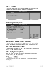
... primary boot device. Chipset Settings NorthBridge Configuration SouthBridge Configuration NorthBridge Configuration Memory Reference Code(MRC) Version 6.5 Boot Graphics Adapter Priority [PEG/IGD] Current Memory Clock :274MHz Surround View Function [Disabled] UMA Frame Buffer Size [64MB] Advanced NB Video...options: [32MB] [64MB] [128MB] Video Display Devices [Auto] Allow you to display video. Configuration options: [NTSC] [PAL] ASUS P5RD2-VM 2-23 Configuration options: [IGD] [PEG/IGD] [PCI/IGD] UMA Frame Buffer Size [64MB] This option allow you to set ...
... primary boot device. Chipset Settings NorthBridge Configuration SouthBridge Configuration NorthBridge Configuration Memory Reference Code(MRC) Version 6.5 Boot Graphics Adapter Priority [PEG/IGD] Current Memory Clock :274MHz Surround View Function [Disabled] UMA Frame Buffer Size [64MB] Advanced NB Video...options: [32MB] [64MB] [128MB] Video Display Devices [Auto] Allow you to display video. Configuration options: [NTSC] [PAL] ASUS P5RD2-VM 2-23 Configuration options: [IGD] [PEG/IGD] [PCI/IGD] UMA Frame Buffer Size [64MB] This option allow you to set ...

Motherboard Installation Guide
Page 73
... [Yes] When set to [No], BIOS does not assign an IRQ to the PCI VGA card even if requested. Configuration options: [Disabled] [Enabled] ASUS P5RD2-VM 2-27 2.4.6 PCI PnP The PCI PnP menu items allow you to select the value in units of the PCI PnP menu items. Incorrect field... required for legacy ISA devices. The menu includes setting IRQ and DMA channel resources for either PCI/PnP or legacy ISA devices, and setting the memory size block for boot. Plug And Play O/S PCI Latency Timer Allocate IRQ to PCI VGA Palette Snooping [No] [64] [Yes] [Disabled] IRQ-3 assigned to ...
... [Yes] When set to [No], BIOS does not assign an IRQ to the PCI VGA card even if requested. Configuration options: [Disabled] [Enabled] ASUS P5RD2-VM 2-27 2.4.6 PCI PnP The PCI PnP menu items allow you to select the value in units of the PCI PnP menu items. Incorrect field... required for legacy ISA devices. The menu includes setting IRQ and DMA channel resources for either PCI/PnP or legacy ISA devices, and setting the memory size block for boot. Plug And Play O/S PCI Latency Timer Allocate IRQ to PCI VGA Palette Snooping [No] [64] [Yes] [Disabled] IRQ-3 assigned to ...


