
Motherboard Installation Guide
Page 5
... 4.5.1 Suspend Mode 4-29 4.5.2 Repost Video on S3 Resume 4-29 4.5.3 ACPI 2.0 Support 4-29 4.5.4 ACPI APIC Support 4-29 4.5.5 APM Configuration 4-30 4.5.6 Hardware Monitor 4-32 4.6 Boot menu 4-33 4.6.1 Boot Device Priority 4-33 4.6.2 Boot Settings Configuration 4-34 4.6.3 Security 4-35 4.7 Exit menu 4-37 Chapter 5: Software support 5.1 Installing an operating system 5-1 5.2 Support CD information 5-1 5.2.1 Running the support CD 5-1 5.2.2 Drivers...
... 4.5.1 Suspend Mode 4-29 4.5.2 Repost Video on S3 Resume 4-29 4.5.3 ACPI 2.0 Support 4-29 4.5.4 ACPI APIC Support 4-29 4.5.5 APM Configuration 4-30 4.5.6 Hardware Monitor 4-32 4.6 Boot menu 4-33 4.6.1 Boot Device Priority 4-33 4.6.2 Boot Settings Configuration 4-34 4.6.3 Security 4-35 4.7 Exit menu 4-37 Chapter 5: Software support 5.1 Installing an operating system 5-1 5.2 Support CD information 5-1 5.2.1 Running the support CD 5-1 5.2.2 Drivers...

Motherboard Installation Guide
Page 18
...page 4-32 for details. 1-4 Chapter 1: Product introduction See pages 4-21 and 5-9 for details. See details on page 4-5. ASUS Q-Fan 2 technology The ASUS Q-Fan 2 technology smartly adjusts the fan speeds according to the system loading to restore the original BIOS data from the support... immediately diagnoses the LAN cable(s) and reports shorts and faults up to your system with customizable boot logos. 1.3.2 ASUS Proactive features AI NOS™ (Non-Delay Overclocking System) ASUS Non-delay Overclocking System™ (NOS) is a BIOS-based diagnostic tool that auto-detects the...
...page 4-32 for details. 1-4 Chapter 1: Product introduction See pages 4-21 and 5-9 for details. See details on page 4-5. ASUS Q-Fan 2 technology The ASUS Q-Fan 2 technology smartly adjusts the fan speeds according to the system loading to restore the original BIOS data from the support... immediately diagnoses the LAN cable(s) and reports shorts and faults up to your system with customizable boot logos. 1.3.2 ASUS Proactive features AI NOS™ (Non-Delay Overclocking System) ASUS Non-delay Overclocking System™ (NOS) is a BIOS-based diagnostic tool that auto-detects the...

Motherboard Installation Guide
Page 33
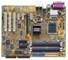
...; Due to chipset resource allocation, the system may cause memory sizing error or system boot failure. For optimum compatibility, it is recommended that you installed four 1 GB DDR memory modules. ASUS P5RD1-V 2-13 DIMM_A1 DIMM_A2 DIMM_B1 DIMM_B2 80 Pins 104 Pins 2.4 System memory 2.4.1 Overview ...The motherboard comes with the same CAS latency. Use any of the sockets: P5RD1-V ® P5RD1-V 184-pin DDR DIMM sockets 2.4.2 Memory configurations ...
...; Due to chipset resource allocation, the system may cause memory sizing error or system boot failure. For optimum compatibility, it is recommended that you installed four 1 GB DDR memory modules. ASUS P5RD1-V 2-13 DIMM_A1 DIMM_A2 DIMM_B1 DIMM_B2 80 Pins 104 Pins 2.4 System memory 2.4.1 Overview ...The motherboard comes with the same CAS latency. Use any of the sockets: P5RD1-V ® P5RD1-V 184-pin DDR DIMM sockets 2.4.2 Memory configurations ...
Motherboard Installation Guide
Page 40
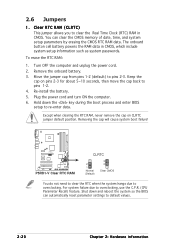
...you to overclocking, use the C.P.R. (CPU Parameter Recall) feature. Turn OFF the computer and unplug the power cord. 2. Removing the cap will cause system boot failure! 2.6 Jumpers 1. To erase the RTC RAM: 1. For system failure due to clear the Real Time Clock (RTC) RAM in CMOS, which ...default position. Except when clearing the RTC RAM, never remove the cap on pins 2-3 for about 5~10 seconds, then move the cap back to overclocking. P5RD1-V ® P5RD1-V Clear RTC RAM CLRTC 2 1 Normal (Default) 3 2 Clear CMOS You do not need to clear the RTC when the system hangs due to ...
...you to overclocking, use the C.P.R. (CPU Parameter Recall) feature. Turn OFF the computer and unplug the power cord. 2. Removing the cap will cause system boot failure! 2.6 Jumpers 1. To erase the RTC RAM: 1. For system failure due to clear the Real Time Clock (RTC) RAM in CMOS, which ...default position. Except when clearing the RTC RAM, never remove the cap on pins 2-3 for about 5~10 seconds, then move the cap back to overclocking. P5RD1-V ® P5RD1-V Clear RTC RAM CLRTC 2 1 Normal (Default) 3 2 Clear CMOS You do not need to clear the RTC when the system hangs due to ...

Motherboard Installation Guide
Page 49
...a 24-pin ATX power supply unit when installing an add-on PCI Express x16 graphics card. The system may become unstable or may not boot up . • Use of 350 W is recommended for an ATX power supply plugs. ATX power connectors (24-pin EATXPWR, 4-pin ATX12V... +5 Volts Ground +5 Volts Ground +3 Volts +3 Volts Ground +5 Volts +5 Volts +5 Volts -5 Volts Ground Ground Ground PSON# Ground -12 Volts +3 Volts ASUS P5RD1-V 2-29 Find the proper orientation and push down firmly until the connectors completely fit. • Use of an ATX 12 V Specification 2.0-compliant power supply unit...
...a 24-pin ATX power supply unit when installing an add-on PCI Express x16 graphics card. The system may become unstable or may not boot up . • Use of 350 W is recommended for an ATX power supply plugs. ATX power connectors (24-pin EATXPWR, 4-pin ATX12V... +5 Volts Ground +5 Volts Ground +3 Volts +3 Volts Ground +5 Volts +5 Volts +5 Volts -5 Volts Ground Ground Ground PSON# Ground -12 Volts +3 Volts ASUS P5RD1-V 2-29 Find the proper orientation and push down firmly until the connectors completely fit. • Use of an ATX 12 V Specification 2.0-compliant power supply unit...

Motherboard Installation Guide
Page 60
Chapter summary 4.1 Managing and updating your BIOS 4-1 4.2 BIOS setup program 4-11 4.3 Main menu 4-14 4.4 Advanced menu 4-17 4.5 Power menu 4-29 4.6 Boot menu 4-33 4.7 Exit menu 4-37 ASUS P5RD1-V
Chapter summary 4.1 Managing and updating your BIOS 4-1 4.2 BIOS setup program 4-11 4.3 Main menu 4-14 4.4 Advanced menu 4-17 4.5 Power menu 4-29 4.6 Boot menu 4-33 4.7 Exit menu 4-37 ASUS P5RD1-V

Motherboard Installation Guide
Page 62
...[filename] is your optical drive. This utility also allows you to continue. 2. Windows® 2000 environment To create a set of boot disks for the extension name. d. Press , then follow screen instructions to copy the current BIOS file that you created earlier. 2. Copy... disk into the drive. A:\>afudos /oOLDBIOS1.ROM Main filename Extension name 4-2 Chapter 4: BIOS setup Click S t a r t, then select R u n. Boot the system in DOS environment using the AFUDOS utility: • Make sure that D: is any user-assigned filename not more than eight alphanumeric characters for...
...[filename] is your optical drive. This utility also allows you to continue. 2. Windows® 2000 environment To create a set of boot disks for the extension name. d. Press , then follow screen instructions to copy the current BIOS file that you created earlier. 2. Copy... disk into the drive. A:\>afudos /oOLDBIOS1.ROM Main filename Extension name 4-2 Chapter 4: BIOS setup Click S t a r t, then select R u n. Boot the system in DOS environment using the AFUDOS utility: • Make sure that D: is any user-assigned filename not more than eight alphanumeric characters for...

Motherboard Installation Guide
Page 63
... The utility returns to the floppy disk. Updating the BIOS file To update the BIOS file using the AFUDOS utility: 1. Boot the system in DOS mode, then at the DOS prompt. 2. Reading flash ..... You need to type the exact BIOS ...the latest or the original BIOS file on a piece of paper. All rights reserved. Visit the ASUS website (www.asus.com) and download the latest BIOS file for the motherboard. A:\>afudos /oOLDBIOS1.ROM AMI Firmware Update Utility - 3. Version...the BIOS file to the bootable floppy disk you created earlier. 3. A:\>afudos /iP5RD1V.ROM ASUS P5RD1-V 4-3
... The utility returns to the floppy disk. Updating the BIOS file To update the BIOS file using the AFUDOS utility: 1. Boot the system in DOS mode, then at the DOS prompt. 2. Reading flash ..... You need to type the exact BIOS ...the latest or the original BIOS file on a piece of paper. All rights reserved. Visit the ASUS website (www.asus.com) and download the latest BIOS file for the motherboard. A:\>afudos /oOLDBIOS1.ROM AMI Firmware Update Utility - 3. Version...the BIOS file to the bootable floppy disk you created earlier. 3. A:\>afudos /iP5RD1V.ROM ASUS P5RD1-V 4-3

Motherboard Installation Guide
Page 64
...(03.11.24BB)) Copyright (C) 2003 American Megatrends, Inc. done Advance Check........ The utility returns to prevent system boot failure! 5. done Advance Check......... All rights reserved. Reboot the system from the hard disk drive. Version 1.19(ASUS V2.07(03.11.24BB)) Copyright (C) 2003 American Megatrends, Inc. done Verifying flash ... WARNING!! done Please...
...(03.11.24BB)) Copyright (C) 2003 American Megatrends, Inc. done Advance Check........ The utility returns to prevent system boot failure! 5. done Advance Check......... All rights reserved. Reboot the system from the hard disk drive. Version 1.19(ASUS V2.07(03.11.24BB)) Copyright (C) 2003 American Megatrends, Inc. done Verifying flash ... WARNING!! done Please...

Motherboard Installation Guide
Page 65
... corrupted during the updating process. Checking for the original or updated BIOS file. When found ! Checking for floppy... Starting BIOS recovery... Start flashing... ASUS P5RD1-V 4-5 Bad BIOS checksum. Floppy found , the utility reads the BIOS file and starts flashing the corrupted BIOS file. Reading file "P5RD1V.ROM". ... the BIOS from a floppy disk: 1. DO NOT shut down or reset the system while updating the BIOS! You can cause system boot failure! 4. Restart the system after the utility completes the updating process. Bad BIOS checksum. Completed. R O M.
... corrupted during the updating process. Checking for the original or updated BIOS file. When found ! Checking for floppy... Starting BIOS recovery... Start flashing... ASUS P5RD1-V 4-5 Bad BIOS checksum. Floppy found , the utility reads the BIOS file and starts flashing the corrupted BIOS file. Reading file "P5RD1V.ROM". ... the BIOS from a floppy disk: 1. DO NOT shut down or reset the system while updating the BIOS! You can cause system boot failure! 4. Restart the system after the utility completes the updating process. Bad BIOS checksum. Completed. R O M.

Motherboard Installation Guide
Page 66
... Starting BIOS recovery... When no floppy disk is found ! The utility then updates the corrupted BIOS file. Completed. Doing so can cause system boot failure! 4. Visit the ASUS website (www.asus.com) to the optical drive. 3. Start flashing... Floppy not found , the utility automatically checks the optical drive for CD-ROM... Restart the...
... Starting BIOS recovery... When no floppy disk is found ! The utility then updates the corrupted BIOS file. Completed. Doing so can cause system boot failure! 4. Visit the ASUS website (www.asus.com) to the optical drive. 3. Start flashing... Floppy not found , the utility automatically checks the optical drive for CD-ROM... Restart the...

Motherboard Installation Guide
Page 67
... done. Insert the floppy disk that you to update the BIOS without having to go through the long process of booting from a floppy disk and using EZ Flash: 1. Reading file "P5RD1V.ROM". ASUS P5RD1-V 4-7 EZFlash starting BIOS update Checking for floppy... 4. Start erasing.......| Start programming...| Flashed successfully. Rebooting. • Do not shutdown or...
... done. Insert the floppy disk that you to update the BIOS without having to go through the long process of booting from a floppy disk and using EZ Flash: 1. Reading file "P5RD1V.ROM". ASUS P5RD1-V 4-7 EZFlash starting BIOS update Checking for floppy... 4. Start erasing.......| Start programming...| Flashed successfully. Rebooting. • Do not shutdown or...

Motherboard Installation Guide
Page 72
...Sub-menu items Navigation keys 4.2.2 Menu bar The menu bar on top of the screen has the following main items: Main Advanced Power Boot Exit For changing the basic system configuration For changing the advanced system settings For changing the advanced power management (APM) configuration For changing... the system boot configuration For selecting the exit options and loading default settings To select an item on the menu bar, press the right or ...
...Sub-menu items Navigation keys 4.2.2 Menu bar The menu bar on top of the screen has the following main items: Main Advanced Power Boot Exit For changing the basic system configuration For changing the advanced system settings For changing the advanced power management (APM) configuration For changing... the system boot configuration For selecting the exit options and loading default settings To select an item on the menu bar, press the right or ...

Motherboard Installation Guide
Page 73
...] :[Not Detected] :[Not Detected] :[Not Detected] Use [ENTER], [TAB] or [SHIFT-TAB] to display the other items (Advanced, Power, Boot, and Exit) on any menu screen means that is highlighted when selected. Advanced Chipset settings WARNING: Setting wrong values in the sections below may cause ...screen. You cannot select an item that the iteam has a sub-menu. Refer to "4.2.7 Pop-up window." 4.2.7 Pop-up window Scroll bar ASUS P5RD1-V 4-13 Change Field Tab Select Field F1 General Help F10 Save and Exit ESC Exit Main menu items A solid triangle before each item on the...
...] :[Not Detected] :[Not Detected] :[Not Detected] Use [ENTER], [TAB] or [SHIFT-TAB] to display the other items (Advanced, Power, Boot, and Exit) on any menu screen means that is highlighted when selected. Advanced Chipset settings WARNING: Setting wrong values in the sections below may cause ...screen. You cannot select an item that the iteam has a sub-menu. Refer to "4.2.7 Pop-up window." 4.2.7 Pop-up window Scroll bar ASUS P5RD1-V 4-13 Change Field Tab Select Field F1 General Help F10 Save and Exit ESC Exit Main menu items A solid triangle before each item on the...

Motherboard Installation Guide
Page 82
... F10 Save and Exit ESC Exit Ratio CMOS Setting [ 8] Sets the ratio between CPU Core Clock and the FSB Frequency. Use the or keys to boot legacy operating systems that cannot support CPUs with extended CPUID functions. NOTE: If an invalid ratio is auto-detected by BIOS. This item appears only...
... F10 Save and Exit ESC Exit Ratio CMOS Setting [ 8] Sets the ratio between CPU Core Clock and the FSB Frequency. Use the or keys to boot legacy operating systems that cannot support CPUs with extended CPUID functions. NOTE: If an invalid ratio is auto-detected by BIOS. This item appears only...

Motherboard Installation Guide
Page 84
...configuration submenu allows you to change the advanced chipset settings. Surround View Function [Disabled] Allows you to use as the primary boot device. This item is not user configurable. PCI Express Graphics Current Memory Clock [400MHz] Displays the current memory clock. ...user configurable. Configuration options: [Disabled] [Enabled] 4-24 Chapter 4: BIOS setup Select an item then press to select the primary graphics boot device. Boots Graphic Adapter Priority [PEG/IGD] Allows you to display the sub-menu. DRAM CAS Select [2.5 Clocks] Displays the DRAM CAS Select clock...
...configuration submenu allows you to change the advanced chipset settings. Surround View Function [Disabled] Allows you to use as the primary boot device. This item is not user configurable. PCI Express Graphics Current Memory Clock [400MHz] Displays the current memory clock. ...user configurable. Configuration options: [Disabled] [Enabled] 4-24 Chapter 4: BIOS setup Select an item then press to select the primary graphics boot device. Boots Graphic Adapter Priority [PEG/IGD] Allows you to display the sub-menu. DRAM CAS Select [2.5 Clocks] Displays the DRAM CAS Select clock...

Motherboard Installation Guide
Page 86
...ATA Controller [Enabled] Enables or disables the Serial ATA controller. Configuration options: [Disabled] [Enabled] OnBoard SATA Boot ROM [Enabled] Enables or disables the onboard Serial ATA boot ROM. Configuration options: [Disabled] [Enabled] Onboard LAN [Enabled] Enables or disables the Onboard LAN controller. ...T V O n l y option if you to display the sub-menu items. AC97 & Azalia LINK A Serial ATA Controller OnBoard SATA Boot ROM Onboard LAN OnBoard LAN Boot ROM [Azalia Only] [Enabled] [Disabled] [Enabled] [Enabled] AC97 & Azalia LINK A [Azalia Only] Disables or sets the AC97...
...ATA Controller [Enabled] Enables or disables the Serial ATA controller. Configuration options: [Disabled] [Enabled] OnBoard SATA Boot ROM [Enabled] Enables or disables the onboard Serial ATA boot ROM. Configuration options: [Disabled] [Enabled] Onboard LAN [Enabled] Enables or disables the Onboard LAN controller. ...T V O n l y option if you to display the sub-menu items. AC97 & Azalia LINK A Serial ATA Controller OnBoard SATA Boot ROM Onboard LAN OnBoard LAN Boot ROM [Azalia Only] [Enabled] [Disabled] [Enabled] [Enabled] AC97 & Azalia LINK A [Azalia Only] Disables or sets the AC97...

Motherboard Installation Guide
Page 88
...], BIOS does not assign an IRQ to the PCI VGA card even if requested. When set to [PCI Device], the specific IRQ is reserved for boot. Configuration options: [No] [Yes] IRQ-xx assigned to, DMA Channel x [PCI Device] When set to [Yes] and if you install a Plug and Play operating system...
...], BIOS does not assign an IRQ to the PCI VGA card even if requested. When set to [PCI Device], the specific IRQ is reserved for boot. Configuration options: [No] [Yes] IRQ-xx assigned to, DMA Channel x [PCI Device] When set to [Yes] and if you install a Plug and Play operating system...

Motherboard Installation Guide
Page 93
... Drive] [Disabled] ASUS P5RD1-V 4-33 Select an item then press to change the system boot options. Boot Settings Boot Device Priority Boot Settings Configuration Security 4.6.1 Boot Device Priority Boot Device Priority 1st Boot Device 2nd Boot Device 3rd Boot Device [1st FLOPPY DRIVE] [PM-ST330620A] [PS-ASUS CD-S360] 1st ~ xxth Boot Device [1st Floppy Drive] These items specify the boot device priority sequence...
... Drive] [Disabled] ASUS P5RD1-V 4-33 Select an item then press to change the system boot options. Boot Settings Boot Device Priority Boot Settings Configuration Security 4.6.1 Boot Device Priority Boot Device Priority 1st Boot Device 2nd Boot Device 3rd Boot Device [1st FLOPPY DRIVE] [PM-ST330620A] [PS-ASUS CD-S360] 1st ~ xxth Boot Device [1st Floppy Drive] These items specify the boot device priority sequence...

Motherboard Installation Guide
Page 94
...skip some power on state for option ROM. Configuration options: [Disabled] [Enabled] 4-34 Chapter 4: BIOS setup 4.6.2 Boot Settings Configuration Boot Settings Configuration Quick Boot Full Screen Logo AddOn ROM Display Mode Bootup Num-Lock PS/2 Mouse Support Wait For 'F1' If Error Hit '...DEL' Message Display Interrupt 19 Capture [Enabled] [Enabled] [Force BIOS] [On] [Auto] [Enabled] [Enabled] [Disabled] Allows BIOS to use the ASUS ...
...skip some power on state for option ROM. Configuration options: [Disabled] [Enabled] 4-34 Chapter 4: BIOS setup 4.6.2 Boot Settings Configuration Boot Settings Configuration Quick Boot Full Screen Logo AddOn ROM Display Mode Bootup Num-Lock PS/2 Mouse Support Wait For 'F1' If Error Hit '...DEL' Message Display Interrupt 19 Capture [Enabled] [Enabled] [Force BIOS] [On] [Auto] [Enabled] [Enabled] [Disabled] Allows BIOS to use the ASUS ...


