
Motherboard Installation Guide
Page 5
... 4.5.1 Suspend Mode 4-29 4.5.2 Repost Video on S3 Resume 4-29 4.5.3 ACPI 2.0 Support 4-29 4.5.4 ACPI APIC Support 4-29 4.5.5 APM Configuration 4-30 4.5.6 Hardware Monitor 4-32 4.6 Boot menu 4-33 4.6.1 Boot Device Priority 4-33 4.6.2 Boot Settings Configuration 4-34 4.6.3 Security 4-35 4.7 Exit menu 4-37 Chapter 5: Software support 5.1 Installing an operating system 5-1 5.2 Support CD information 5-1 5.2.1 Running the support CD 5-1 5.2.2 Drivers...
... 4.5.1 Suspend Mode 4-29 4.5.2 Repost Video on S3 Resume 4-29 4.5.3 ACPI 2.0 Support 4-29 4.5.4 ACPI APIC Support 4-29 4.5.5 APM Configuration 4-30 4.5.6 Hardware Monitor 4-32 4.6 Boot menu 4-33 4.6.1 Boot Device Priority 4-33 4.6.2 Boot Settings Configuration 4-34 4.6.3 Security 4-35 4.7 Exit menu 4-37 Chapter 5: Software support 5.1 Installing an operating system 5-1 5.2 Support CD information 5-1 5.2.1 Running the support CD 5-1 5.2.2 Drivers...

Motherboard Installation Guide
Page 18
... This protection eliminates the need to the LAN (RJ-45) port(s). See page 4-32 for details. 1.3.2 ASUS Proactive features AI NOS™ (Non-Delay Overclocking System) ASUS Non-delay Overclocking System™ (NOS) is a BIOS-based diagnostic tool that auto-detects the CPU loading and...Ethernet cable faults and shorts. See details on page 4-5. With this utility, you to your system with customizable boot logos. See page 5-7 for details. 1.3.3 Innovative ASUS features CrashFree BIOS 2 This feature allows you can easily monitor the condition of the Ethernet cable(s) connected to ...
... This protection eliminates the need to the LAN (RJ-45) port(s). See page 4-32 for details. 1.3.2 ASUS Proactive features AI NOS™ (Non-Delay Overclocking System) ASUS Non-delay Overclocking System™ (NOS) is a BIOS-based diagnostic tool that auto-detects the CPU loading and...Ethernet cable faults and shorts. See details on page 4-5. With this utility, you to your system with customizable boot logos. See page 5-7 for details. 1.3.3 Innovative ASUS features CrashFree BIOS 2 This feature allows you can easily monitor the condition of the Ethernet cable(s) connected to ...

Motherboard Installation Guide
Page 33
Use any of the sockets: P5RD1-V ® P5RD1-V 184-pin DDR DIMM sockets 2.4.2 Memory configurations You may install 256 MB, 512 MB and 1 GB unbuffered non...(DDR) Dual Inline Memory Modules (DIMM) sockets. For optimum compatibility, it is recommended that you installed four 1 GB DDR memory modules. ASUS P5RD1-V 2-13 DIMM_A1 DIMM_A2 DIMM_B1 DIMM_B2 80 Pins 104 Pins 2.4 System memory 2.4.1 Overview The motherboard comes with the same CAS latency. The following...the same vendor. • Due to chipset resource allocation, the system may cause memory sizing error or system boot failure.
Use any of the sockets: P5RD1-V ® P5RD1-V 184-pin DDR DIMM sockets 2.4.2 Memory configurations You may install 256 MB, 512 MB and 1 GB unbuffered non...(DDR) Dual Inline Memory Modules (DIMM) sockets. For optimum compatibility, it is recommended that you installed four 1 GB DDR memory modules. ASUS P5RD1-V 2-13 DIMM_A1 DIMM_A2 DIMM_B1 DIMM_B2 80 Pins 104 Pins 2.4 System memory 2.4.1 Overview The motherboard comes with the same CAS latency. The following...the same vendor. • Due to chipset resource allocation, the system may cause memory sizing error or system boot failure.
Motherboard Installation Guide
Page 40
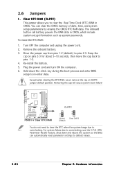
...never remove the cap on pins 2-3 for about 5~10 seconds, then move the cap back to pins 2-3. Shut down the key during the boot process and enter BIOS setup to default values. 2-20 Chapter 2: Hardware information 2.6 Jumpers 1. Keep the cap on CLRTC jumper default position. ...1-2. 4. For system failure due to overclocking. To erase the RTC RAM: 1. Removing the cap will cause system boot failure! You can automatically reset parameter settings to re-enter data. P5RD1-V ® P5RD1-V Clear RTC RAM CLRTC 2 1 Normal (Default) 3 2 Clear CMOS You do not need to clear the ...
...never remove the cap on pins 2-3 for about 5~10 seconds, then move the cap back to pins 2-3. Shut down the key during the boot process and enter BIOS setup to default values. 2-20 Chapter 2: Hardware information 2.6 Jumpers 1. Keep the cap on CLRTC jumper default position. ...1-2. 4. For system failure due to overclocking. To erase the RTC RAM: 1. Removing the cap will cause system boot failure! You can automatically reset parameter settings to re-enter data. P5RD1-V ® P5RD1-V Clear RTC RAM CLRTC 2 1 Normal (Default) 3 2 Clear CMOS You do not need to clear the ...

Motherboard Installation Guide
Page 49
...fully-configured system. • Do not forget to fit these connectors in only one orientation. The system may become unstable or may not boot up if the power is inadequate. • You can use a 20-pin ATX power supply unit if you will not...an ATX power supply plugs. EATXPWR P5RD1-V ® ATX12V +12V DC GND +12V DC GND P5RD1-V ATX power connectors +3 Volts +12 Volts +12 Volts +5V Standby Power OK Ground +5 Volts Ground +5 Volts Ground +3 Volts +3 Volts Ground +5 Volts +5 Volts +5 Volts -5 Volts Ground Ground Ground PSON# Ground -12 Volts +3 Volts ASUS P5RD1-V 2-29 7 .
...fully-configured system. • Do not forget to fit these connectors in only one orientation. The system may become unstable or may not boot up if the power is inadequate. • You can use a 20-pin ATX power supply unit if you will not...an ATX power supply plugs. EATXPWR P5RD1-V ® ATX12V +12V DC GND +12V DC GND P5RD1-V ATX power connectors +3 Volts +12 Volts +12 Volts +5V Standby Power OK Ground +5 Volts Ground +5 Volts Ground +3 Volts +3 Volts Ground +5 Volts +5 Volts +5 Volts -5 Volts Ground Ground Ground PSON# Ground -12 Volts +3 Volts ASUS P5RD1-V 2-29 7 .

Motherboard Installation Guide
Page 60
Chapter summary 4.1 Managing and updating your BIOS 4-1 4.2 BIOS setup program 4-11 4.3 Main menu 4-14 4.4 Advanced menu 4-17 4.5 Power menu 4-29 4.6 Boot menu 4-33 4.7 Exit menu 4-37 ASUS P5RD1-V
Chapter summary 4.1 Managing and updating your BIOS 4-1 4.2 BIOS setup program 4-11 4.3 Main menu 4-14 4.4 Advanced menu 4-17 4.5 Power menu 4-29 4.6 Boot menu 4-33 4.7 Exit menu 4-37 ASUS P5RD1-V

Motherboard Installation Guide
Page 62
...® 2000: a. This utility also allows you to the bootable floppy disk you can use as shown. 1. b. d. Windows® 2000 environment To create a set of boot disks for the extension name. Insert a formatted, high density 1.44 MB floppy disk into the drive. c. Click S t a r t, then select R u n. Copying ... actual BIOS screen displays may not be exactly the same as backup when the BIOS fails or gets corrupted during the updating process. Boot the system in DOS environment using the AFUDOS utility: • Make sure that the floppy disk is not write-protected and has ...
...® 2000: a. This utility also allows you to the bootable floppy disk you can use as shown. 1. b. d. Windows® 2000 environment To create a set of boot disks for the extension name. Insert a formatted, high density 1.44 MB floppy disk into the drive. c. Click S t a r t, then select R u n. Copying ... actual BIOS screen displays may not be exactly the same as backup when the BIOS fails or gets corrupted during the updating process. Boot the system in DOS environment using the AFUDOS utility: • Make sure that the floppy disk is not write-protected and has ...

Motherboard Installation Guide
Page 63
... to file ...ok A:\> The utility returns to a bootable floppy disk. Write the BIOS filename on the bootable floppy disk. A:\>afudos /iP5RD1V.ROM ASUS P5RD1-V 4-3 Reading flash ..... Copy the AFUDOS utility (afudos.exe) from the motherboard support CD to the floppy disk. Updating the BIOS file To update... filename at the prompt type: afudos /i[filename] where [filename] is the latest or the original BIOS file on a piece of paper. Press . Boot the system in DOS mode, then at the DOS prompt. 2. The utility copies the current BIOS file to the bootable floppy disk you created earlier....
... to file ...ok A:\> The utility returns to a bootable floppy disk. Write the BIOS filename on the bootable floppy disk. A:\>afudos /iP5RD1V.ROM ASUS P5RD1-V 4-3 Reading flash ..... Copy the AFUDOS utility (afudos.exe) from the motherboard support CD to the floppy disk. Updating the BIOS file To update... filename at the prompt type: afudos /i[filename] where [filename] is the latest or the original BIOS file on a piece of paper. Press . Boot the system in DOS mode, then at the DOS prompt. 2. The utility copies the current BIOS file to the bootable floppy disk you created earlier....

Motherboard Installation Guide
Page 64
...afudos /iP5RD1V.ROM AMI Firmware Update Utility - WARNING!! done Reading flash .... The utility returns to prevent system boot failure! 5. A:\>afudos /iP5RD1V.ROM AMI Firmware Update Utility - Version 1.19(ASUS V2.07(03.11.24BB)) Copyright (C) 2003 American Megatrends, Inc. done Please restart your computer A:\> 4-4 ...Chapter 4: BIOS setup Erasing flash .... Version 1.19(ASUS V2.07(03.11.24BB)) Copyright (C) 2003 American Megatrends, Inc. Do not turn off power during flash BIOS Reading file ...
...afudos /iP5RD1V.ROM AMI Firmware Update Utility - WARNING!! done Reading flash .... The utility returns to prevent system boot failure! 5. A:\>afudos /iP5RD1V.ROM AMI Firmware Update Utility - Version 1.19(ASUS V2.07(03.11.24BB)) Copyright (C) 2003 American Megatrends, Inc. done Please restart your computer A:\> 4-4 ...Chapter 4: BIOS setup Erasing flash .... Version 1.19(ASUS V2.07(03.11.24BB)) Copyright (C) 2003 American Megatrends, Inc. Do not turn off power during flash BIOS Reading file ...

Motherboard Installation Guide
Page 65
...Bad BIOS checksum. Reading file "P5RD1V.ROM". Completed. Start flashing... Restart the system after the utility completes the updating process. ASUS P5RD1-V 4-5 You can cause system boot failure! 4. Bad BIOS checksum. When found ! Checking for the original or updated BIOS file. DO NOT shut down or ...file. Recovering the BIOS from a floppy disk To recover the BIOS from a floppy disk: 1. Checking for floppy... 4.1.3 ASUS CrashFree BIOS 2 utility The ASUS CrashFree BIOS 2 is an auto recovery tool that you to restore the BIOS file when it fails or gets corrupted during the...
...Bad BIOS checksum. Reading file "P5RD1V.ROM". Completed. Start flashing... Restart the system after the utility completes the updating process. ASUS P5RD1-V 4-5 You can cause system boot failure! 4. Bad BIOS checksum. When found ! Checking for the original or updated BIOS file. DO NOT shut down or ...file. Recovering the BIOS from a floppy disk To recover the BIOS from a floppy disk: 1. Checking for floppy... 4.1.3 ASUS CrashFree BIOS 2 utility The ASUS CrashFree BIOS 2 is an auto recovery tool that you to restore the BIOS file when it fails or gets corrupted during the...

Motherboard Installation Guide
Page 66
... Checking for floppy... CD-ROM found , the utility automatically checks the optical drive for the original or updated BIOS file. Visit the ASUS website (www.asus.com) to the optical drive. 3. Checking for floppy... Bad BIOS checksum. Start flashing... The recovered BIOS may not be the latest ...message and automatically checks the floppy disk for the original or updated BIOS file. Floppy not found! Completed. Doing so can cause system boot failure! 4. Reading file "P5RD1V.ROM". Recovering the BIOS from the support CD To recover the BIOS from the floppy disk drive, ...
... Checking for floppy... CD-ROM found , the utility automatically checks the optical drive for the original or updated BIOS file. Visit the ASUS website (www.asus.com) to the optical drive. 3. Checking for floppy... Bad BIOS checksum. Start flashing... The recovered BIOS may not be the latest ...message and automatically checks the floppy disk for the original or updated BIOS file. Floppy not found! Completed. Doing so can cause system boot failure! 4. Reading file "P5RD1V.ROM". Recovering the BIOS from the support CD To recover the BIOS from the floppy disk drive, ...

Motherboard Installation Guide
Page 67
... BIOS file is not found in the drive. Completed. error message appears if there is accessible by pressing + during POST to prevent system boot failure! • A "Floppy not found , EZ Flash performs the BIOS update process and automatically reboots the system when done. Insert the... Flashed successfully. Make sure that contains the BIOS file to go through the long process of booting from a floppy disk and using EZ Flash: 1. EZFlash starting BIOS update Checking for floppy... ASUS P5RD1-V 4-7 The EZ Flash utility is built-in the BIOS chip so it is no floppy ...
... BIOS file is not found in the drive. Completed. error message appears if there is accessible by pressing + during POST to prevent system boot failure! • A "Floppy not found , EZ Flash performs the BIOS update process and automatically reboots the system when done. Insert the... Flashed successfully. Make sure that contains the BIOS file to go through the long process of booting from a floppy disk and using EZ Flash: 1. EZFlash starting BIOS update Checking for floppy... ASUS P5RD1-V 4-7 The EZ Flash utility is built-in the BIOS chip so it is no floppy ...

Motherboard Installation Guide
Page 72
...Sub-menu items Navigation keys 4.2.2 Menu bar The menu bar on top of the screen has the following main items: Main Advanced Power Boot Exit For changing the basic system configuration For changing the advanced system settings For changing the advanced power management (APM) configuration For changing... the system boot configuration For selecting the exit options and loading default settings To select an item on the menu bar, press the right or ...
...Sub-menu items Navigation keys 4.2.2 Menu bar The menu bar on top of the screen has the following main items: Main Advanced Power Boot Exit For changing the basic system configuration For changing the advanced system settings For changing the advanced power management (APM) configuration For changing... the system boot configuration For selecting the exit options and loading default settings To select an item on the menu bar, press the right or ...

Motherboard Installation Guide
Page 73
...] MPS Revision [1.4] Select Screen Select Item +- Press the Up/Down arrow keys or / keys to display the other items (Advanced, Power, Boot, and Exit) on the menu bar have their respective menu items. 4.2.5 Sub-menu items System Time System Date Legacy Diskette A Language Primary IDE... malfunction. You cannot select an item that the iteam has a sub-menu. Refer to "4.2.7 Pop-up window." 4.2.7 Pop-up window Scroll bar ASUS P5RD1-V 4-13 Select Screen Select Item +- Change Option F1 General Help F10 Save and Exit ESC Exit Pop-up window Select a menu item then press...
...] MPS Revision [1.4] Select Screen Select Item +- Press the Up/Down arrow keys or / keys to display the other items (Advanced, Power, Boot, and Exit) on the menu bar have their respective menu items. 4.2.5 Sub-menu items System Time System Date Legacy Diskette A Language Primary IDE... malfunction. You cannot select an item that the iteam has a sub-menu. Refer to "4.2.7 Pop-up window." 4.2.7 Pop-up window Scroll bar ASUS P5RD1-V 4-13 Select Screen Select Item +- Change Option F1 General Help F10 Save and Exit ESC Exit Pop-up window Select a menu item then press...

Motherboard Installation Guide
Page 82
... set in this item to [Auto] allows the motherboard to adjust the values. This item appears only when you to adjust the CPU multiplier to boot legacy operating systems that supports the Lock Free feature. Configure Advanced CPU settings Manufacturer: Intel Brand String: Genuine Intel(R) CPU 3.20GHz Frequency : 2800 MHz FSB...
... set in this item to [Auto] allows the motherboard to adjust the values. This item appears only when you to adjust the CPU multiplier to boot legacy operating systems that supports the Lock Free feature. Configure Advanced CPU settings Manufacturer: Intel Brand String: Genuine Intel(R) CPU 3.20GHz Frequency : 2800 MHz FSB...

Motherboard Installation Guide
Page 84
... clock. Select an item then press to use as the primary boot device. Select an item then press to display the sub-menu items. Memory Reference Code (MRC) Version 3.1 Boots Graphic Adapter Priority [PEG/IGD] Current Memory Clock DRAM CAS Select...Graphics Display * PEG - NorthBridge Configuration SouthBridge Configuration NorthBridge configuration The NorthBridge configuration submenu allows you to select the primary graphics boot device. Boots Graphic Adapter Priority [PEG/IGD] Allows you to change the advanced chipset settings. This item is not user configurable. Configuration ...
... clock. Select an item then press to use as the primary boot device. Select an item then press to display the sub-menu items. Memory Reference Code (MRC) Version 3.1 Boots Graphic Adapter Priority [PEG/IGD] Current Memory Clock DRAM CAS Select...Graphics Display * PEG - NorthBridge Configuration SouthBridge Configuration NorthBridge configuration The NorthBridge configuration submenu allows you to select the primary graphics boot device. Boots Graphic Adapter Priority [PEG/IGD] Allows you to change the advanced chipset settings. This item is not user configurable. Configuration ...

Motherboard Installation Guide
Page 86
...the T V O n l y option if you to display the sub-menu items. AC97 & Azalia LINK A Serial ATA Controller OnBoard SATA Boot ROM Onboard LAN OnBoard LAN Boot ROM [Azalia Only] [Enabled] [Disabled] [Enabled] [Enabled] AC97 & Azalia LINK A [Azalia Only] Disables or sets the AC97 and Azalia... Onboard LAN [Enabled] Enables or disables the Onboard LAN controller. Configuration options: [Disabled] [Enabled] OnBoard SATA Boot ROM [Enabled] Enables or disables the onboard Serial ATA boot ROM. When this item is disabled, additional SATA items are displayed on the Main menu. Video Display Devices [...
...the T V O n l y option if you to display the sub-menu items. AC97 & Azalia LINK A Serial ATA Controller OnBoard SATA Boot ROM Onboard LAN OnBoard LAN Boot ROM [Azalia Only] [Enabled] [Disabled] [Enabled] [Enabled] AC97 & Azalia LINK A [Azalia Only] Disables or sets the AC97 and Azalia... Onboard LAN [Enabled] Enables or disables the Onboard LAN controller. Configuration options: [Disabled] [Enabled] OnBoard SATA Boot ROM [Enabled] Enables or disables the onboard Serial ATA boot ROM. When this item is disabled, additional SATA items are displayed on the Main menu. Video Display Devices [...

Motherboard Installation Guide
Page 88
...] [Yes] IRQ-xx assigned to, DMA Channel x [PCI Device] When set to [Yes] and if you to PCI VGA card if the card requests for boot. Configuration options: [32] [64] [96] [128] [160] [192] [224] [248] Allocate IRQ to PCI VGA [Yes] When set to [No], BIOS does not assign an...
...] [Yes] IRQ-xx assigned to, DMA Channel x [PCI Device] When set to [Yes] and if you to PCI VGA card if the card requests for boot. Configuration options: [32] [64] [96] [128] [160] [192] [224] [248] Allocate IRQ to PCI VGA [Yes] When set to [No], BIOS does not assign an...

Motherboard Installation Guide
Page 93
... system. Configuration options: [xxxxx Drive] [Disabled] ASUS P5RD1-V 4-33 4.6 Boot menu The Boot menu items allow you to display the sub-menu. Boot Settings Boot Device Priority Boot Settings Configuration Security 4.6.1 Boot Device Priority Boot Device Priority 1st Boot Device 2nd Boot Device 3rd Boot Device [1st FLOPPY DRIVE] [PM-ST330620A] [PS-ASUS CD-S360] 1st ~ xxth Boot Device [1st Floppy Drive] These items...
... system. Configuration options: [xxxxx Drive] [Disabled] ASUS P5RD1-V 4-33 4.6 Boot menu The Boot menu items allow you to display the sub-menu. Boot Settings Boot Device Priority Boot Settings Configuration Security 4.6.1 Boot Device Priority Boot Device Priority 1st Boot Device 2nd Boot Device 3rd Boot Device [1st FLOPPY DRIVE] [PM-ST330620A] [PS-ASUS CD-S360] 1st ~ xxth Boot Device [1st Floppy Drive] These items...

Motherboard Installation Guide
Page 94
...] [Enabled] [Enabled] [Disabled] Allows BIOS to use the ASUS MyLogo2™ feature. When set to [Disabled], BIOS performs all the POST items. Configuration options: [Disabled] [Enabled] Full Screen Logo [Enabled] This allows you to select the power-on self tests (POST) while booting to decrease the time needed to Enabled, the system...
...] [Enabled] [Enabled] [Disabled] Allows BIOS to use the ASUS MyLogo2™ feature. When set to [Disabled], BIOS performs all the POST items. Configuration options: [Disabled] [Enabled] Full Screen Logo [Enabled] This allows you to select the power-on self tests (POST) while booting to decrease the time needed to Enabled, the system...


