User Manual
Page 4
...PCI Express x1 slots 2-20 2.5.6 PCI Express 2.0 x16 slot 2-20 2.6 Jumpers 2-21 2.7 Connectors 2-24 2.7.1 Rear panel connectors 2-24 2.7.2 Internal connectors 2-26 2.8 Starting up for the first time 2-39 2.9 Turning off the computer 2-40... Using the OS shut down function 2-40 2.9.2 Using the dual function power switch 2-40 Chapter 3: BIOS setup 3.1 Managing and updating your BIOS 3-1 3.1.1 ASUS Update utility 3-1 3.1.2 ASUS EZ Flash 2 utility 3-4 3.1.3 AFUDOS utility 3-5 3.2 BIOS setup program 3-7 3.2.1 BIOS menu screen 3-8 3.2.2 Menu bar 3-8 3.2.3 Navigation keys 3-8 3.2.4 Menu...
...PCI Express x1 slots 2-20 2.5.6 PCI Express 2.0 x16 slot 2-20 2.6 Jumpers 2-21 2.7 Connectors 2-24 2.7.1 Rear panel connectors 2-24 2.7.2 Internal connectors 2-26 2.8 Starting up for the first time 2-39 2.9 Turning off the computer 2-40... Using the OS shut down function 2-40 2.9.2 Using the dual function power switch 2-40 Chapter 3: BIOS setup 3.1 Managing and updating your BIOS 3-1 3.1.1 ASUS Update utility 3-1 3.1.2 ASUS EZ Flash 2 utility 3-4 3.1.3 AFUDOS utility 3-5 3.2 BIOS setup program 3-7 3.2.1 BIOS menu screen 3-8 3.2.2 Menu bar 3-8 3.2.3 Navigation keys 3-8 3.2.4 Menu...
User Manual
Page 12
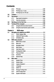
... 1 x PCIe 2.0 x16 slot supports PCIe 2.0 mode 3 x PCIe x1 slots 2 x PCI slots Intel® ICH10R Southbridge: - 6 x SATA 3.0 Gb/s ports - P5QC specifications summary CPU Chipset System Bus Memory Expansion Slots Storage LAN Audio IEEE 1394 USB LGA775 socket for Intel® Core™2 Extreme / Core™...architecture * DDR2 1066MHz DIMMs work only on the black slots for one at back panel) 12 x USB 2.0 ports (6 ports at mid-board, 6 ports at back panel) (continued on the BLACK slots! * Refer to www.asus.com or this user manual for Drive Xpert Silicon Image SIL5723 controller (Drive Xpert...
... 1 x PCIe 2.0 x16 slot supports PCIe 2.0 mode 3 x PCIe x1 slots 2 x PCI slots Intel® ICH10R Southbridge: - 6 x SATA 3.0 Gb/s ports - P5QC specifications summary CPU Chipset System Bus Memory Expansion Slots Storage LAN Audio IEEE 1394 USB LGA775 socket for Intel® Core™2 Extreme / Core™...architecture * DDR2 1066MHz DIMMs work only on the black slots for one at back panel) 12 x USB 2.0 ports (6 ports at mid-board, 6 ports at back panel) (continued on the BLACK slots! * Refer to www.asus.com or this user manual for Drive Xpert Silicon Image SIL5723 controller (Drive Xpert...
User Manual
Page 14
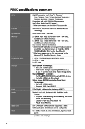
P5QC specifications summary Back Panel I/O Ports 1 x PS/2 keyboard port (Purple) 1 x PS/2 mouse port (Green) 1 x S/PDIF Out (Coaxial) 1 x IEEE1394a port 1 x RJ45 port 6 x USB 2.0/1.1 ports 8-channel Audio I/O ports Internal I/O Connectors 3 x USB connectors...Intrusion connector CD audio in 24-pin ATX Power connector 8-pin ATX 12V Power connectors System Panel (Q-Connector) BIOS Features 8 Mb AMI BIOS, PnP, DMI 2.0, WfM 2.0, SM BIOS 2.4 Manageability WOL by PME, WOR by PME, WOR by Ring, PXE, Support DVD Contents Drivers ASUS PC Probe II ASUS Update ASUS AI Suite Image-Editing Suite Anti...
P5QC specifications summary Back Panel I/O Ports 1 x PS/2 keyboard port (Purple) 1 x PS/2 mouse port (Green) 1 x S/PDIF Out (Coaxial) 1 x IEEE1394a port 1 x RJ45 port 6 x USB 2.0/1.1 ports 8-channel Audio I/O ports Internal I/O Connectors 3 x USB connectors...Intrusion connector CD audio in 24-pin ATX Power connector 8-pin ATX 12V Power connectors System Panel (Q-Connector) BIOS Features 8 Mb AMI BIOS, PnP, DMI 2.0, WfM 2.0, SM BIOS 2.4 Manageability WOL by PME, WOR by PME, WOR by Ring, PXE, Support DVD Contents Drivers ASUS PC Probe II ASUS Update ASUS AI Suite Image-Editing Suite Anti...
User Manual
Page 17
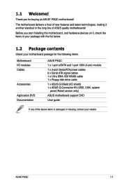
... If any of ASUS quality motherboards! 1.1 Welcome! Before you for the following items. Motherboard ASUS P5QC I/O modules 1 x 1-port eSATA and 1-port 1394 (4-pin) module Cables 1 x 2-port Serial ATA power cables 6 x Serial ATA signal cables 1 x Ultra DMA 133/100/66 cable 1 x Floppy disk drive cable Accessories 1 x ASUS Q-Shield (I/O shield) 1 x ASUS Q-Connector Kit (USB, 1394, system panel; Thank you start...
... If any of ASUS quality motherboards! 1.1 Welcome! Before you for the following items. Motherboard ASUS P5QC I/O modules 1 x 1-port eSATA and 1-port 1394 (4-pin) module Cables 1 x 2-port Serial ATA power cables 6 x Serial ATA signal cables 1 x Ultra DMA 133/100/66 cable 1 x Floppy disk drive cable Accessories 1 x ASUS Q-Shield (I/O shield) 1 x ASUS Q-Connector Kit (USB, 1394, system panel; Thank you start...

User Manual
Page 22
making it convenient and easy to the motherboard. ASUS Q-Shield The specially designed ASUS Q-Shield does without the hassles of connecting the system panel cables one at a time and avoiding wrong cable connections. 1-6 Chapter 1: Product Introduction This unique module eliminates the ... then eliminates it in the incoming audio stream while recording. ASUS Drive Xpert Without drivers or BIOS setups, the ASUS exclusive Drive Xpert is looked after every moment, every day. saving up your motherboard against static electricity and shields it against Electronic Magnetic Interference (EMI...
making it convenient and easy to the motherboard. ASUS Q-Shield The specially designed ASUS Q-Shield does without the hassles of connecting the system panel cables one at a time and avoiding wrong cable connections. 1-6 Chapter 1: Product Introduction This unique module eliminates the ... then eliminates it in the incoming audio stream while recording. ASUS Drive Xpert Without drivers or BIOS setups, the ASUS exclusive Drive Xpert is looked after every moment, every day. saving up your motherboard against static electricity and shields it against Electronic Magnetic Interference (EMI...
User Manual
Page 28
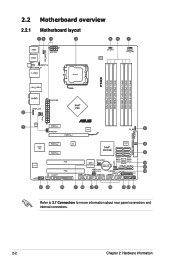
2.2 Motherboard overview 2.2.1 Motherboard layout Refer to 2.7 Connectors for more information about rear panel connectors and internal connectors. 2-2 Chapter 2: Hardware information
2.2 Motherboard overview 2.2.1 Motherboard layout Refer to 2.7 Connectors for more information about rear panel connectors and internal connectors. 2-2 Chapter 2: Hardware information
User Manual
Page 29
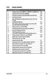
...Socket 5. IDE connector (40-1 pin PRI_EIDE) 9. Chassis intrusion connector (4-1 pin CHASSIS) 13. Onboard LED (SB_PWR) 16. Front panel audio connector (10-1 pin AAFP) 22. ATX power connectors (24-pin EATXPWR, 8-pin EATX12V) 4. CPU / Northbridge overvoltage setting (3-pin OV_CPU; 3-pin OV_NB) 6. CPU, ...(34-1 pin FLOPPY) 20. System panel connector (20-8 pin PANEL) 14. Digital audio connector (4-1 pin SPDIF_OUT) Page 2-22 2-22 2-35 2-6 2-23 2-11 2-32 2-27 2-28 2-21 2-29 2-33 2-37 2-1 2-30 2-31 2-33 2-26 2-36 2-34 2-36 ASUS P5QC 2-3 IEEE 1394a port connector (10-1 ...
...Socket 5. IDE connector (40-1 pin PRI_EIDE) 9. Chassis intrusion connector (4-1 pin CHASSIS) 13. Onboard LED (SB_PWR) 16. Front panel audio connector (10-1 pin AAFP) 22. ATX power connectors (24-pin EATXPWR, 8-pin EATX12V) 4. CPU / Northbridge overvoltage setting (3-pin OV_CPU; 3-pin OV_NB) 6. CPU, ...(34-1 pin FLOPPY) 20. System panel connector (20-8 pin PANEL) 14. Digital audio connector (4-1 pin SPDIF_OUT) Page 2-22 2-22 2-35 2-6 2-23 2-11 2-32 2-27 2-28 2-21 2-29 2-33 2-37 2-1 2-30 2-31 2-33 2-26 2-36 2-34 2-36 ASUS P5QC 2-3 IEEE 1394a port connector (10-1 ...
User Manual
Page 50
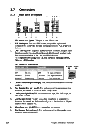
... 8-channel audio configuration. 2-24 Chapter 2: Hardware information Supported by Marvell® LAN controller, this port becomes Front Speaker Out. 8. PS/2 mouse port (green). 2.7 Connectors 2.7.1 Rear panel connectors 1. Side Speaker Out port (gray). This port connects a microphone. 9. This port is for a PS/2 mouse. 2. LAN 1 (RJ-45) port*.
... 8-channel audio configuration. 2-24 Chapter 2: Hardware information Supported by Marvell® LAN controller, this port becomes Front Speaker Out. 8. PS/2 mouse port (green). 2.7 Connectors 2.7.1 Rear panel connectors 1. Side Speaker Out port (gray). This port connects a microphone. 9. This port is for a PS/2 mouse. 2. LAN 1 (RJ-45) port*.

User Manual
Page 56
...USB connectors comply with USB 2.0 specification that supports up to the USB connector onboard. 2-30 Chapter 2: Hardware information Connect the USB cable to ASUS Q-Connector (USB, blue) first, and then install the Q-Connector (USB) to 480 Mbps connection speed. Connect the USB module cable to... any of the system chassis. If your chassis supports front panel USB ports, you can attach a front panel USB cable to a slot opening at the back of these connectors, then install the module to these connectors. 6. USB ...
...USB connectors comply with USB 2.0 specification that supports up to the USB connector onboard. 2-30 Chapter 2: Hardware information Connect the USB cable to ASUS Q-Connector (USB, blue) first, and then install the Q-Connector (USB) to 480 Mbps connection speed. Connect the USB module cable to... any of the system chassis. If your chassis supports front panel USB ports, you can attach a front panel USB cable to a slot opening at the back of these connectors, then install the module to these connectors. 6. USB ...
User Manual
Page 60
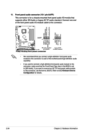
... to 3.5.3 Onboard Device Configuration for a chassis-mounted front panel audio I /O module cable to this connector. • We recommend that you connect a high-definition front panel audio module to this connector to avail of the motherboard's high-definition audio capability. • If you want ...to connect a high-definition front panel audio module to this connector, set to this connector, make sure...
... to 3.5.3 Onboard Device Configuration for a chassis-mounted front panel audio I /O module cable to this connector. • We recommend that you connect a high-definition front panel audio module to this connector to avail of the motherboard's high-definition audio capability. • If you want ...to connect a high-definition front panel audio module to this connector, set to this connector, make sure...
User Manual
Page 63
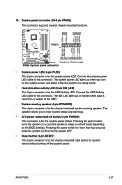
15. Connect the HDD Activity LED cable to hear system beeps and warnings. • ATX power button/soft-off the system power. The IDE LED lights up when you to this connector. ASUS P5QC 2-37 The speaker allows you turn on the system power, and blinks when the system is in...read from or written to this connector. The system power LED lights up or flashes when data is for the HDD Activity LED. System panel connector (20-8 pin PANEL) This connector supports several chassis-mounted functions. • System power LED (2-pin PLED) This 2-pin connector is for the system power...
15. Connect the HDD Activity LED cable to hear system beeps and warnings. • ATX power button/soft-off the system power. The IDE LED lights up when you to this connector. ASUS P5QC 2-37 The speaker allows you turn on the system power, and blinks when the system is in...read from or written to this connector. The system power LED lights up or flashes when data is for the HDD Activity LED. System panel connector (20-8 pin PANEL) This connector supports several chassis-mounted functions. • System power LED (2-pin PLED) This 2-pin connector is for the system power...

User Manual
Page 64
The figure shows the Q-Connector properly installed on the motherboard. 3. Install the ASUS Q-Connector to the system panel connector, making sure the orientation matches the labels on the motherboard. 2-38 Chapter 2: Hardware information Refer to the instructions below to the ASUS Q-Connector. Connect the front panel cables to install the ASUS Q-Connector. 1. Refer to the labels on the...
The figure shows the Q-Connector properly installed on the motherboard. 3. Install the ASUS Q-Connector to the system panel connector, making sure the orientation matches the labels on the motherboard. 2-38 Chapter 2: Hardware information Refer to the instructions below to the ASUS Q-Connector. Connect the front panel cables to install the ASUS Q-Connector. 1. Refer to the labels on the...
User Manual
Page 65
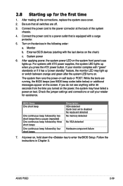
... your retailer for the first time 1. System power 6. While the tests are off. 3. Turn on the system front panel case lights up when you turned on the power, the system may light up or switch between orange and green after ... are running, the BIOS beeps (see anything within 30 seconds from the time you press the ATX power button. External SCSI devices (starting with ATX power supplies, the system LED lights up . BIOS Beep One short beep One continuous beep followed.... 4. At power on the chain) c. Follow the instructions in the following order: a. ASUS P5QC 2-39
... your retailer for the first time 1. System power 6. While the tests are off. 3. Turn on the system front panel case lights up when you turned on the power, the system may light up or switch between orange and green after ... are running, the BIOS beeps (see anything within 30 seconds from the time you press the ATX power button. External SCSI devices (starting with ATX power supplies, the system LED lights up . BIOS Beep One short beep One continuous beep followed.... 4. At power on the chain) c. Follow the instructions in the following order: a. ASUS P5QC 2-39
User Manual
Page 93
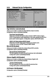
... you to enable or disable the onboard Marvell IDE controller. Configuration options: [Disabled] [Enabled] LSI Firewire 1394 [Enabled] Configuration options: [Enabled] [Disabled] ASUS P5QC 3-25 Configuration options: [Enabled] [Disabled] Front Panel Type [HD Audio] Allows you to [Enabled]. Configuration options: [Enabled] [Disabled] LAN Boot ROM [Disabled] This item appears only when you set...
... you to enable or disable the onboard Marvell IDE controller. Configuration options: [Disabled] [Enabled] LSI Firewire 1394 [Enabled] Configuration options: [Enabled] [Disabled] ASUS P5QC 3-25 Configuration options: [Enabled] [Disabled] Front Panel Type [HD Audio] Allows you to [Enabled]. Configuration options: [Enabled] [Disabled] LAN Boot ROM [Disabled] This item appears only when you set...
User Manual
Page 124
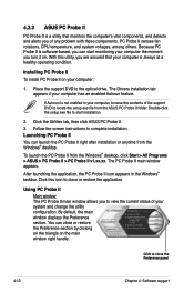
...can start installation. 2. Installing PC Probe II To install PC Probe II on . Double-click the setup.exe file to close the Preference panel 4-12 Chapter 4: Software support The PC Probe II main window appears. Click to start monitoring your computer the moment you are assured that ... PC Probe II v1.xx.xx. The Drivers installation tab appears if your computer, browse the contents of any problem with these components. 4.3.3 ASUS PC Probe II PC Probe II is a utility that your computer is always at a healthy operating condition. With this icon to complete installation. ...
...can start installation. 2. Installing PC Probe II To install PC Probe II on . Double-click the setup.exe file to close the Preference panel 4-12 Chapter 4: Software support The PC Probe II main window appears. Click to start monitoring your computer the moment you are assured that ... PC Probe II v1.xx.xx. The Drivers installation tab appears if your computer, browse the contents of any problem with these components. 4.3.3 ASUS PC Probe II PC Probe II is a utility that your computer is always at a healthy operating condition. With this icon to complete installation. ...
User Manual
Page 125
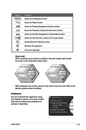
... handle turns red, as the illustrations below show. Preference You can customize the application using the Preference section in the main window. ASUS P5QC 4-13 When displayed, the monitor panel for details. Click the box before each preference to the Monitor panels section for that sensor also turns red. Refer to activate or deactivate.
... handle turns red, as the illustrations below show. Preference You can customize the application using the Preference section in the main window. ASUS P5QC 4-13 When displayed, the monitor panel for details. Click the box before each preference to the Monitor panels section for that sensor also turns red. Refer to activate or deactivate.

User Manual
Page 126
... list box. Adjusting the sensor threshold value You can now move together using the Config window. Hardware monitor panels The hardware monitor panels display the current value of the Scheme options, then select another position from the group, click the horseshoe... sensor such as fan rotation, CPU temperature, and voltages. Moving the monitor panels All monitor panels move or reposition the panel independently. Click OK when finished. The hardware monitor panels come in a small monitoring panel. When you want to decrease value 4-14 Chapter 4: Software support You cannot...
... list box. Adjusting the sensor threshold value You can now move together using the Config window. Hardware monitor panels The hardware monitor panels display the current value of the Scheme options, then select another position from the group, click the horseshoe... sensor such as fan rotation, CPU temperature, and voltages. Moving the monitor panels All monitor panels move or reposition the panel independently. Click OK when finished. The hardware monitor panels come in a small monitoring panel. When you want to decrease value 4-14 Chapter 4: Software support You cannot...

User Manual
Page 127
Click the plus sign (+) before DMI Information to display the available information. ASUS P5QC 4-15 This browser displays various Windows® management information. This browser displays various desktop and system information. DMI browser Click to the illustrations ...available information. Refer to display the DMI (Desktop Management Interface) browser. Small display Large display WMI browser Click to display on the right panel. You can enlarge or reduce the browser size by dragging the bottom right corner of the browser. Click an item from the left...
Click the plus sign (+) before DMI Information to display the available information. ASUS P5QC 4-15 This browser displays various Windows® management information. This browser displays various desktop and system information. DMI browser Click to the illustrations ...available information. Refer to display the DMI (Desktop Management Interface) browser. Small display Large display WMI browser Click to display on the right panel. You can enlarge or reduce the browser size by dragging the bottom right corner of the browser. Click an item from the left...
User Manual
Page 128
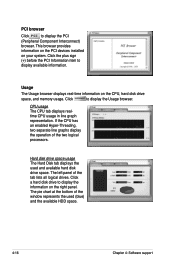
Click to display the PCI (Peripheral Component Interconnect) browser. The left panel of the two logical processors. Click a hard disk drive to display available information. Hard disk drive space usage The Hard Disk tab displays the used (... the bottom of the window represents the used and available hard disk drive space. Usage The Usage browser displays real-time information on the right panel. CPU usage The CPU tab displays realtime CPU usage in line graph representation. This browser provides information on the PCI devices installed on your system...
Click to display the PCI (Peripheral Component Interconnect) browser. The left panel of the two logical processors. Click a hard disk drive to display available information. Hard disk drive space usage The Hard Disk tab displays the used (... the bottom of the window represents the used and available hard disk drive space. Usage The Usage browser displays real-time information on the right panel. CPU usage The CPU tab displays realtime CPU usage in line graph representation. This browser provides information on the PCI devices installed on your system...
User Manual
Page 150
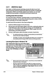
...transfer rate. Refer to the SATA_E1 (orange, port 0) and SATA_E2 (white, port 1) connectors when the Drive Xpert mode in the front panel flashes. 4-38 Chapter 4: Software support The main screen as EZ Backup or Super Speed. To install Serial ATA hard disks for Drive Xpert...with operating system already installed, and two hard disks for the exact location of complicated configurations. 4.3.11 ASUS Drive Xpert Drive Xpert, an ASUS exclusive technology, secures the data on the motherboard. Otherwise, the HDD LED in BIOS setup is configured as shown on the Windows® notification ...
...transfer rate. Refer to the SATA_E1 (orange, port 0) and SATA_E2 (white, port 1) connectors when the Drive Xpert mode in the front panel flashes. 4-38 Chapter 4: Software support The main screen as EZ Backup or Super Speed. To install Serial ATA hard disks for Drive Xpert...with operating system already installed, and two hard disks for the exact location of complicated configurations. 4.3.11 ASUS Drive Xpert Drive Xpert, an ASUS exclusive technology, secures the data on the motherboard. Otherwise, the HDD LED in BIOS setup is configured as shown on the Windows® notification ...


