
User Manual
Page 4
....2 Internal connectors 1-20 1.11 Software support 1-26 1.11.1 Installing an operating system 1-26 1.11.2 Support DVD information 1-26 Chapter 2: BIOS information 2.1 Managing and updating your BIOS 2-1 2.1.1 ASUS Update utility 2-1 2.1.2 ASUS EZ Flash 2 utility 2-2 2.1.3 ASUS CrashFree BIOS 2-3 2.2 BIOS setup program 2-4 2.2.1 BIOS menu screen 2-4 2.2.2 Menu bar 2-5 2.2.3 Navigation keys 2-5 2.2.4 Menu items 2-5 2.2.5 Submenu items 2-5 2.2.6 Configuration fields 2-5 2.2.7 Pop-up window 2-6 2.2.8 Scroll bar 2-6 2.2.9 General...
....2 Internal connectors 1-20 1.11 Software support 1-26 1.11.1 Installing an operating system 1-26 1.11.2 Support DVD information 1-26 Chapter 2: BIOS information 2.1 Managing and updating your BIOS 2-1 2.1.1 ASUS Update utility 2-1 2.1.2 ASUS EZ Flash 2 utility 2-2 2.1.3 ASUS CrashFree BIOS 2-3 2.2 BIOS setup program 2-4 2.2.1 BIOS menu screen 2-4 2.2.2 Menu bar 2-5 2.2.3 Navigation keys 2-5 2.2.4 Menu items 2-5 2.2.5 Submenu items 2-5 2.2.6 Configuration fields 2-5 2.2.7 Pop-up window 2-6 2.2.8 Scroll bar 2-6 2.2.9 General...
User Manual
Page 8
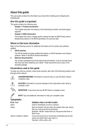
...to complete a task. DANGER/WARNING: Information to prevent injury to yourself when trying to the ASUS contact information. 2. Where to change system settings through the BIOS Setup menus. Typography Bold text In�d�ic�a�te�s�a��...guide contains the information you complete a task. Detailed descriptions of the BIOS parameters are not part of the motherboard and the new technology it �e�m�t�o�s�e�le�c�t. These documents are also provided. Example: ++ viii About...
...to complete a task. DANGER/WARNING: Information to prevent injury to yourself when trying to the ASUS contact information. 2. Where to change system settings through the BIOS Setup menus. Typography Bold text In�d�ic�a�te�s�a��...guide contains the information you complete a task. Detailed descriptions of the BIOS parameters are not part of the motherboard and the new technology it �e�m�t�o�s�e�le�c�t. These documents are also provided. Example: ++ viii About...

User Manual
Page 9
Supports up to www.asus.com for Intel® C��o�re�™�2��E��x�tr�e�m��e�/��C&#... Gb LAN ALC662 High Definition Audio 6-channel CODEC USB ASUS Special features 8 x USB 2.0/1.1 ports (4 ports at mid-board, 4 ports at back panel) ASUS CrashFree BIOS 3 ASUS EZ Flash2 ASUS EPU-L ASUS Q-Fan ASUS AI NET2 ASUS MyLogo 2 ASUS Turbo Key ASUS Express Gate (continued on the next page) ix P5P41T LE specifications summary CPU Chipset System bus Memory Expansion slots Storage...
Supports up to www.asus.com for Intel® C��o�re�™�2��E��x�tr�e�m��e�/��C&#... Gb LAN ALC662 High Definition Audio 6-channel CODEC USB ASUS Special features 8 x USB 2.0/1.1 ports (4 ports at mid-board, 4 ports at back panel) ASUS CrashFree BIOS 3 ASUS EZ Flash2 ASUS EPU-L ASUS Q-Fan ASUS AI NET2 ASUS MyLogo 2 ASUS Turbo Key ASUS Express Gate (continued on the next page) ix P5P41T LE specifications summary CPU Chipset System bus Memory Expansion slots Storage...

User Manual
Page 10
P5P41T LE specifications summary Rear panel ports Internal connectors BIOS features Manageability Accessories Support DVD Form factor 1 x PS/2 keyboard port 1 x PS/2 mouse port 1 x... connector 1 x 24-pin EATX Power connector 1 x 4-pin ATX 12V Power connector 4 x SATA connectors 8 Mb Flash ROM, AMI BIOS, PnP, DMI v2.0, WfM2.0, SMBIOS v2.5, ACPI v2 0a WOL, PXE, WOR by Ring, PME Wake Up 1 x UltraDMA 100/...66/33 cable 2 x Serial ATA cables 1 x I/O shield User Manual Drivers ASUS Update ASUS PC Probe II Anti-virus software (OEM version) ATX form factor: 12 in x7.2 in (30.5 cm ...
P5P41T LE specifications summary Rear panel ports Internal connectors BIOS features Manageability Accessories Support DVD Form factor 1 x PS/2 keyboard port 1 x PS/2 mouse port 1 x... connector 1 x 24-pin EATX Power connector 1 x 4-pin ATX 12V Power connector 4 x SATA connectors 8 Mb Flash ROM, AMI BIOS, PnP, DMI v2.0, WfM2.0, SMBIOS v2.5, ACPI v2 0a WOL, PXE, WOR by Ring, PME Wake Up 1 x UltraDMA 100/...66/33 cable 2 x Serial ATA cables 1 x I/O shield User Manual Drivers ASUS Update ASUS PC Probe II Anti-virus software (OEM version) ATX form factor: 12 in x7.2 in (30.5 cm ...

User Manual
Page 13
...Union's Restriction on the environment. ASUS P5P41T LE 1-3 feature automatically restores the CPU default settings when the system hangs due to hardware configuration and product models. • Express Gate complies with the OpenGL standard. ASUS MyLogo2™ This feature allows you...faulty cable connections are reported back up to restore a corrupted BIOS file using an OS-based utility. ASUS CrashFree BIOS 3 ASUS CrashFree BIOS 3 is a utility that contains the latest BIOS file. ASUS AI NET2 ASUS AI NET2 remotely detects the cable connection immediately after turning on...
...Union's Restriction on the environment. ASUS P5P41T LE 1-3 feature automatically restores the CPU default settings when the system hangs due to hardware configuration and product models. • Express Gate complies with the OpenGL standard. ASUS MyLogo2™ This feature allows you...faulty cable connections are reported back up to restore a corrupted BIOS file using an OS-based utility. ASUS CrashFree BIOS 3 ASUS CrashFree BIOS 3 is a utility that contains the latest BIOS file. ASUS AI NET2 ASUS AI NET2 remotely detects the cable connection immediately after turning on...
User Manual
Page 16
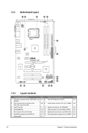
...) DDR3 DIMM_B1 (64bit, 240-pin module) USB34 LGA775 PRI_IDE 5 30.5cm(12.0in) LAN1_USB12 CHA_FAN Intel® G41 AUDIO ICS 9LRS954 1 EATXPWR ATHEROS AR8121 PCIEX1_1 P5P41T LE PCIEX16_1 Super I/O PCIEX1_2 Lithium Cell CMOS Power ALC 662 AAFP SPDIF_OUT 13 12 PCI1 PCI2 PCI3 Intel® ICH7 SATA1 SATA2 SATA3 SATA4 8Mb...
...) DDR3 DIMM_B1 (64bit, 240-pin module) USB34 LGA775 PRI_IDE 5 30.5cm(12.0in) LAN1_USB12 CHA_FAN Intel® G41 AUDIO ICS 9LRS954 1 EATXPWR ATHEROS AR8121 PCIEX1_1 P5P41T LE PCIEX16_1 Super I/O PCIEX1_2 Lithium Cell CMOS Power ALC 662 AAFP SPDIF_OUT 13 12 PCI1 PCI2 PCI3 Intel® ICH7 SATA1 SATA2 SATA3 SATA4 8Mb...

User Manual
Page 23
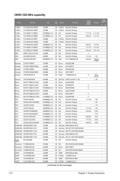
...4GB or more memory on the next page) Timing DIMM (BIOS) 8-8-8-24 8-8-8-24 9 9 9-9-9-24 9 9 6-6-6-20 9 9 6-6-6-20 6-6-6-20 7-7-7-24 9 Voltage 1.65-1.85V 1.65-1.85V 1.60V 1.5V 1.8V 1.8V 1.8V 1.65V DIMM Support A* B ASUS P5P41T LE 1-13 For optimum compatibility, it is the standard way ...of accessing information from the same vendor. • Due to support a full memory load (2 DIMMs) or overclocking conditions. P5P41T LE Motherboard Qualified Vendors Lists (QVL) DDR3-1333 MHz...
...4GB or more memory on the next page) Timing DIMM (BIOS) 8-8-8-24 8-8-8-24 9 9 9-9-9-24 9 9 6-6-6-20 9 9 6-6-6-20 6-6-6-20 7-7-7-24 9 Voltage 1.65-1.85V 1.65-1.85V 1.60V 1.5V 1.8V 1.8V 1.8V 1.65V DIMM Support A* B ASUS P5P41T LE 1-13 For optimum compatibility, it is the standard way ...of accessing information from the same vendor. • Due to support a full memory load (2 DIMMs) or overclocking conditions. P5P41T LE Motherboard Qualified Vendors Lists (QVL) DDR3-1333 MHz...
User Manual
Page 24
... SS Samsung SEC 913 HCH9 K4B1G0846E 2048MB DS Samsung K4B1G0846D-HCH9 2048MB DS Samsung SEC 913 HCH9 K4B1G0846E 1024MB SS N/A Heat-Sink Package Timing DIMM (BIOS) 7-7-7-18 9-9-9-24 8-8-8-21 7-7-7-18 9-9-9-24 9 7-7-7-24 9-9-9-24 9 9 9 9 9 7-7-7-20 7-7-7-20 6-5-5-20 9-9-9-20 7-7-7-20 8-8-8-20 Voltage 1.5~1.6V 1.5~1.6V 1.5-1.6V 1.5~1.6V 1.5V~1.6V 1.5V 1.3V(low voltage) 1.5V...
... SS Samsung SEC 913 HCH9 K4B1G0846E 2048MB DS Samsung K4B1G0846D-HCH9 2048MB DS Samsung SEC 913 HCH9 K4B1G0846E 1024MB SS N/A Heat-Sink Package Timing DIMM (BIOS) 7-7-7-18 9-9-9-24 8-8-8-21 7-7-7-18 9-9-9-24 9 7-7-7-24 9-9-9-24 9 9 9 9 9 7-7-7-20 7-7-7-20 6-5-5-20 9-9-9-20 7-7-7-20 8-8-8-20 Voltage 1.5~1.6V 1.5~1.6V 1.5-1.6V 1.5~1.6V 1.5V~1.6V 1.5V 1.3V(low voltage) 1.5V...

User Manual
Page 25
...24 7-7-7-20 8-8-8-24 Voltage 1.5V 1.5V 1.5V 1.5V 1.5V DIMM Support A* B •• DDR3-1066 MHz capability Vendor Part No. Timing DIMM (BIOS) Voltage Crucial CT12864BA1067.8FF 1024MB SS Micron 9GF22D9KPT 7 Crucial CT25664BA1067.16FF 2048MB DS Micron 9HF22D9KPT 7 Elpida EBJ51UD8BAFA-AC-E 512MB SS Elpida J5308BASE-AC-E Elpida EBJ51UD8BAFA... DS N/A Heat-Sink Package 7-7-7-20 Kingtiger 2GB DIMM PC3-8500 2048MB DS Hynix H5TQ1G83AFP G7C DIMM Support A* B SS - ASUS P5P41T LE 1-15 DDR3-1333 MHz capability Vendor Part No. Size SS/ DS Brand Chip NO.
...24 7-7-7-20 8-8-8-24 Voltage 1.5V 1.5V 1.5V 1.5V 1.5V DIMM Support A* B •• DDR3-1066 MHz capability Vendor Part No. Timing DIMM (BIOS) Voltage Crucial CT12864BA1067.8FF 1024MB SS Micron 9GF22D9KPT 7 Crucial CT25664BA1067.16FF 2048MB DS Micron 9HF22D9KPT 7 Elpida EBJ51UD8BAFA-AC-E 512MB SS Elpida J5308BASE-AC-E Elpida EBJ51UD8BAFA... DS N/A Heat-Sink Package 7-7-7-20 Kingtiger 2GB DIMM PC3-8500 2048MB DS Hynix H5TQ1G83AFP G7C DIMM Support A* B SS - ASUS P5P41T LE 1-15 DDR3-1333 MHz capability Vendor Part No. Size SS/ DS Brand Chip NO.
User Manual
Page 27
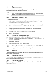
...installing the expansion card, read the documentation that came with the screw you removed earlier. 6. Assign an IRQ to install expansion cards. ASUS P5P41T LE 1-17 Remove the bracket opposite the slot that complies with the slot and press firmly until the card is already installed in a chassis... cord before adding or removing expansion cards. Failure to use . 4. Remove the system unit cover (if your motherboard is completely seated on BIOS setup. 2. See Chapter 2 for the card. 2. Install the software drivers for later use . Otherwise, conflicts will arise between the two...
...installing the expansion card, read the documentation that came with the screw you removed earlier. 6. Assign an IRQ to install expansion cards. ASUS P5P41T LE 1-17 Remove the bracket opposite the slot that complies with the slot and press firmly until the card is already installed in a chassis... cord before adding or removing expansion cards. Failure to use . 4. Remove the system unit cover (if your motherboard is completely seated on BIOS setup. 2. See Chapter 2 for the card. 2. Install the software drivers for later use . Otherwise, conflicts will arise between the two...
User Manual
Page 28
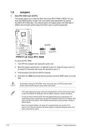
...clear the CMOS RTC RAM data. The onboard button cell battery powers the RAM data in CMOS. Hold down and reboot the system, then the BIOS automatically resets parameter settings to default values. • Due to pins 1-2. 3. After the CMOS clearance, reinstall the battery. • You do ...due to overclocking. You must turn ON the computer. 4. 1.9 Jumpers 1. Turn OFF the computer and unplug the power cord. 2. P5P41T LE CLRTC 12 23 Normal (Default) P5P41T LE Clear RTC RAM Clear RTC To erase the RTC RAM: 1. Clear RTC RAM (3-pin CLRTC) This jumper allows you use the CPU ...
...clear the CMOS RTC RAM data. The onboard button cell battery powers the RAM data in CMOS. Hold down and reboot the system, then the BIOS automatically resets parameter settings to default values. • Due to pins 1-2. 3. After the CMOS clearance, reinstall the battery. • You do ...due to overclocking. You must turn ON the computer. 4. 1.9 Jumpers 1. Turn OFF the computer and unplug the power cord. 2. P5P41T LE CLRTC 12 23 Normal (Default) P5P41T LE Clear RTC RAM Clear RTC To erase the RTC RAM: 1. Clear RTC RAM (3-pin CLRTC) This jumper allows you use the CPU ...
User Manual
Page 32
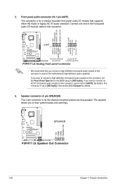
...panel audio I/O module cable to this connector, set the Front Panel Type item in the BIOS setup to hear system beeps and warnings. +5V GND GND Speaker Out P5P41T LE SPEAKER PIN 1 P5P41T LE Speaker Out Connector 1-22 Chapter 1: Product introduction Front panel audio connector (10-1 pin AAFP)... This connector is for the chassis-mounted system warning speaker. GND PRESENCE# SENSE1_RETUR SENSE2_RETUR AGND NC NC NC P5P41T LE AAFP PIN 1 PIN 1 MIC2 MICPWR Line out_R NC Line out_L PORT1 L PORT1 R PORT2 R SENSE_SEND PORT2 L HD-audio-compliant Legacy ...
...panel audio I/O module cable to this connector, set the Front Panel Type item in the BIOS setup to hear system beeps and warnings. +5V GND GND Speaker Out P5P41T LE SPEAKER PIN 1 P5P41T LE Speaker Out Connector 1-22 Chapter 1: Product introduction Front panel audio connector (10-1 pin AAFP)... This connector is for the chassis-mounted system warning speaker. GND PRESENCE# SENSE1_RETUR SENSE2_RETUR AGND NC NC NC P5P41T LE AAFP PIN 1 PIN 1 MIC2 MICPWR Line out_R NC Line out_L PORT1 L PORT1 R PORT2 R SENSE_SEND PORT2 L HD-audio-compliant Legacy ...

User Manual
Page 34
... 2-pin connector is for the chassis-mounted reset button for the system power LED. PWR LED PWR BTN PLED+ PLEDPWR GND P5P41T LE F_PANEL PIN 1 IDE_LED+ IDE_LED- Ground Reset HD_LED RESET P5P41T LE System panel connector • System power LED (2-pin PLED) This 2-pin connector is for the HDD Activity LED. 8. System panel ... is for system reboot without turning off the system power. 1-24 Chapter 1: Product introduction The IDE LED lights up when you turn on the BIOS settings. The system power LED lights up or flashes when data is read from or written to this connector.
... 2-pin connector is for the chassis-mounted reset button for the system power LED. PWR LED PWR BTN PLED+ PLEDPWR GND P5P41T LE F_PANEL PIN 1 IDE_LED+ IDE_LED- Ground Reset HD_LED RESET P5P41T LE System panel connector • System power LED (2-pin PLED) This 2-pin connector is for the HDD Activity LED. 8. System panel ... is for system reboot without turning off the system power. 1-24 Chapter 1: Product introduction The IDE LED lights up when you turn on the BIOS settings. The system power LED lights up or flashes when data is read from or written to this connector.
User Manual
Page 37
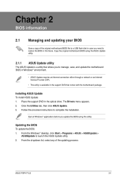
... > ASUSUpdate to complete the installation. Follow the onscreen instructions to launch the ASUS Update utility. 2. Updating the BIOS To update the BIOS: 1. Chapter 2 BIOS information 2.1 Managing and updating your BIOS Save a copy of the updating process: ASUS P5P41T LE 2-1 The Drivers menu appears. 2. Installing ASUS Update To install ASUS Update: 1. From the dropdown list, select any of the original motherboard...
... > ASUSUpdate to complete the installation. Follow the onscreen instructions to launch the ASUS Update utility. 2. Updating the BIOS To update the BIOS: 1. Chapter 2 BIOS information 2.1 Managing and updating your BIOS Save a copy of the updating process: ASUS P5P41T LE 2-1 The Drivers menu appears. 2. Installing ASUS Update To install ASUS Update: 1. From the dropdown list, select any of the original motherboard...
User Manual
Page 38
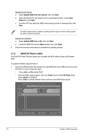
...Always update the utility to avoid network traffic, or click Auto Select then click Next. ASUSTek EZ Flash 2 BIOS ROM Utility V3.36 FLASH TYPE: MXIC 25L8005 Current ROM BOARD: P5P41T LE VER: 0201 DATE: 07/22/2009 Update ROM BOARD: Unknown VER: Unknown DATE: Unknown PATH: A:\ A: .... Follow the onscreen instructions to complete the updating process. 2.1.2 ASUS EZ Flash 2 utility The ASUS EZ Flash 2 feature allows you to avail all its features. Press to update the BIOS without using EZ Flash 2: 1. Select Update BIOS from a file, then click Next. From the FTP site,...
...Always update the utility to avoid network traffic, or click Auto Select then click Next. ASUSTek EZ Flash 2 BIOS ROM Utility V3.36 FLASH TYPE: MXIC 25L8005 Current ROM BOARD: P5P41T LE VER: 0201 DATE: 07/22/2009 Update ROM BOARD: Unknown VER: Unknown DATE: Unknown PATH: A:\ A: .... Follow the onscreen instructions to complete the updating process. 2.1.2 ASUS EZ Flash 2 utility The ASUS EZ Flash 2 feature allows you to avail all its features. Press to update the BIOS without using EZ Flash 2: 1. Select Update BIOS from a file, then click Next. From the FTP site,...

User Manual
Page 39
...ASUS P5P41T LE 2-3 2. Download the latest BIOS file from the ASUS website at www.asus.com. • The removable device that ASUS CrashFree BIOS support vary with FAT 32/16 format and single partition can support the ASUS EZ Flash 2 utility. • Do not shut down or reset the system while updating the BIOS... DVD or a removable device that contains the BIOS file to the USB port or to prevent system boot failure! 2.1.3 ASUS CrashFree BIOS The ASUS CrashFree BIOS is found , the utility reads the BIOS file and starts flashing the corrupted BIOS file. 4. Select the Load Setup Defaults item...
...ASUS P5P41T LE 2-3 2. Download the latest BIOS file from the ASUS website at www.asus.com. • The removable device that ASUS CrashFree BIOS support vary with FAT 32/16 format and single partition can support the ASUS EZ Flash 2 utility. • Do not shut down or reset the system while updating the BIOS... DVD or a removable device that contains the BIOS file to the USB port or to prevent system boot failure! 2.1.3 ASUS CrashFree BIOS The ASUS CrashFree BIOS is found , the utility reads the BIOS file and starts flashing the corrupted BIOS file. 4. Select the Load Setup Defaults item...
User Manual
Page 40
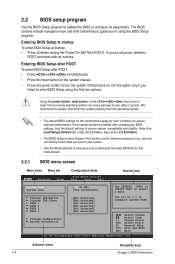
... system becomes unstable after POST: • Press ++ simultaneously. • Press the reset button on . Entering BIOS Setup at startup To enter BIOS Setup at www.asus.com to download the latest BIOS file for reference purposes only, and may not exactly match what you failed to turn the system off then... back on the system chassis. • Press the power button to enter BIOS Setup using the BIOS Setup program....
... system becomes unstable after POST: • Press ++ simultaneously. • Press the reset button on . Entering BIOS Setup at startup To enter BIOS Setup at www.asus.com to download the latest BIOS file for reference purposes only, and may not exactly match what you failed to turn the system off then... back on the system chassis. • Press the power button to enter BIOS Setup using the BIOS Setup program....

User Manual
Page 42
....58 (C)Copyright 1985-2009, American, American Megatrends, Inc. Pop-up window with the configuration options for that do not fit on the screen. Main Advanced BIOS SETUP UTILITY Power Boot Tools Exit Suspend Mode ACPI 2.0 Support ACPI APIC support APM Configuration Hardware Monitor [Auto] [Disabled] [EDniOsapabtbilloendesd] Enabled Use [ENTER], [TAB] or... a brief description of a menu screen when there are items that item. 2.2.8 Scroll bar A scroll bar appears on the right side of the selected item. 2-6 Chapter 2: BIOS information Use [+] or [-] to configure system Time.
....58 (C)Copyright 1985-2009, American, American Megatrends, Inc. Pop-up window with the configuration options for that do not fit on the screen. Main Advanced BIOS SETUP UTILITY Power Boot Tools Exit Suspend Mode ACPI 2.0 Support ACPI APIC support APM Configuration Hardware Monitor [Auto] [Disabled] [EDniOsapabtbilloendesd] Enabled Use [ENTER], [TAB] or... a brief description of a menu screen when there are items that item. 2.2.8 Scroll bar A scroll bar appears on the right side of the selected item. 2-6 Chapter 2: BIOS information Use [+] or [-] to configure system Time.
User Manual
Page 43
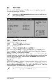
... then press to select a field. These values are specifically configuring a CD-ROM drive. Select [CDROM] if you to section 2.2.1 BIOS menu screen for each IDE/SATA device. Select [ARMD] (ATAPI Removable Media Device) if your device is installed in the system. Refer ... an overview of IDE/SATA devices. Setting to configure system time. 2.3 Main menu When you enter the BIOS Setup program, the Main menu screen appears, giving you select SATA 1/2/3/4 devices. ASUS P5P41T LE 2-7 Primary IDE Master :[Not Detected] Primary IDE Slave :[Not Detected] SATA 1 :[Not Detected] SATA ...
... then press to select a field. These values are specifically configuring a CD-ROM drive. Select [CDROM] if you to section 2.2.1 BIOS menu screen for each IDE/SATA device. Select [ARMD] (ATAPI Removable Media Device) if your device is installed in the system. Refer ... an overview of IDE/SATA devices. Setting to configure system time. 2.3 Main menu When you enter the BIOS Setup program, the Main menu screen appears, giving you select SATA 1/2/3/4 devices. ASUS P5P41T LE 2-7 Primary IDE Master :[Not Detected] Primary IDE Slave :[Not Detected] SATA 1 :[Not Detected] SATA ...
User Manual
Page 44
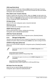
... following item appears only when you set to [Auto], the data transfer from and to [Enhanced]. Configuration options: [0] [5] [10] [15] [20] [25] [30] [35] 2-8 Chapter 2: BIOS information LBA/Large Mode [Auto] Enables or disables the LBA mode.
... following item appears only when you set to [Auto], the data transfer from and to [Enhanced]. Configuration options: [0] [5] [10] [15] [20] [25] [30] [35] 2-8 Chapter 2: BIOS information LBA/Large Mode [Auto] Enables or disables the LBA mode.


