
User Manual
Page 4
....2 Internal connectors 1-20 1.11 Software support 1-26 1.11.1 Installing an operating system 1-26 1.11.2 Support DVD information 1-26 Chapter 2: BIOS information 2.1 Managing and updating your BIOS 2-1 2.1.1 ASUS Update utility 2-1 2.1.2 ASUS EZ Flash 2 utility 2-2 2.1.3 ASUS CrashFree BIOS 2-3 2.2 BIOS setup program 2-4 2.2.1 BIOS menu screen 2-4 2.2.2 Menu bar 2-5 2.2.3 Navigation keys 2-5 2.2.4 Menu items 2-5 2.2.5 Submenu items 2-5 2.2.6 Configuration fields 2-5 2.2.7 Pop-up window 2-6 2.2.8 Scroll bar 2-6 2.2.9 General...
....2 Internal connectors 1-20 1.11 Software support 1-26 1.11.1 Installing an operating system 1-26 1.11.2 Support DVD information 1-26 Chapter 2: BIOS information 2.1 Managing and updating your BIOS 2-1 2.1.1 ASUS Update utility 2-1 2.1.2 ASUS EZ Flash 2 utility 2-2 2.1.3 ASUS CrashFree BIOS 2-3 2.2 BIOS setup program 2-4 2.2.1 BIOS menu screen 2-4 2.2.2 Menu bar 2-5 2.2.3 Navigation keys 2-5 2.2.4 Menu items 2-5 2.2.5 Submenu items 2-5 2.2.6 Configuration fields 2-5 2.2.7 Pop-up window 2-6 2.2.8 Scroll bar 2-6 2.2.9 General...
User Manual
Page 8
... descriptions of the BIOS parameters are linked ...Enter or Return key. ++ If you MUST follow to change system settings through the BIOS Setup menus. Conventions used in the less-than and greater-than sign means that you...; Chapter 2: BIOS information This chapter tells how to complete a task. Italics Used to complete a task. Example: ++ viii ASUS websites The ASUS website provides updated information on ASUS hardware and software... you must press two or more information Refer to the ASUS contact information. 2. These documents are not part of the motherboard and the...
... descriptions of the BIOS parameters are linked ...Enter or Return key. ++ If you MUST follow to change system settings through the BIOS Setup menus. Conventions used in the less-than and greater-than sign means that you...; Chapter 2: BIOS information This chapter tells how to complete a task. Italics Used to complete a task. Example: ++ viii ASUS websites The ASUS website provides updated information on ASUS hardware and software... you must press two or more information Refer to the ASUS contact information. 2. These documents are not part of the motherboard and the...

User Manual
Page 9
... to www.asus.com for Intel® CPU support list Northbridge: Intel® G41 Southbridge: Intel® ICH7 1333/1066/800MHz Dual-channel memory architecture - 2 x 240-pin DIMM sockets support unbuffered non-ECC DDR3 1333 (O.C.)/1066/800MHz memory modules - P5P41T LE specifications summary ... Gb LAN ALC662 High Definition Audio 6-channel CODEC USB ASUS Special features 8 x USB 2.0/1.1 ports (4 ports at mid-board, 4 ports at back panel) ASUS CrashFree BIOS 3 ASUS EZ Flash2 ASUS EPU-L ASUS Q-Fan ASUS AI NET2 ASUS MyLogo 2 ASUS Turbo Key ASUS Express Gate (continued on the next page) ix We...
... to www.asus.com for Intel® CPU support list Northbridge: Intel® G41 Southbridge: Intel® ICH7 1333/1066/800MHz Dual-channel memory architecture - 2 x 240-pin DIMM sockets support unbuffered non-ECC DDR3 1333 (O.C.)/1066/800MHz memory modules - P5P41T LE specifications summary ... Gb LAN ALC662 High Definition Audio 6-channel CODEC USB ASUS Special features 8 x USB 2.0/1.1 ports (4 ports at mid-board, 4 ports at back panel) ASUS CrashFree BIOS 3 ASUS EZ Flash2 ASUS EPU-L ASUS Q-Fan ASUS AI NET2 ASUS MyLogo 2 ASUS Turbo Key ASUS Express Gate (continued on the next page) ix We...

User Manual
Page 10
P5P41T LE specifications summary Rear panel ports Internal connectors BIOS features Manageability Accessories Support DVD Form factor 1 x PS/2 keyboard port 1 x PS/2 mouse port 1 x... connector 1 x 24-pin EATX Power connector 1 x 4-pin ATX 12V Power connector 4 x SATA connectors 8 Mb Flash ROM, AMI BIOS, PnP, DMI v2.0, WfM2.0, SMBIOS v2.5, ACPI v2 0a WOL, PXE, WOR by Ring, PME Wake Up 1 x UltraDMA 100/...66/33 cable 2 x Serial ATA cables 1 x I/O shield User Manual Drivers ASUS Update ASUS PC Probe II Anti-virus software (OEM version) ATX form factor: 12 in x7.2 in (30.5 cm ...
P5P41T LE specifications summary Rear panel ports Internal connectors BIOS features Manageability Accessories Support DVD Form factor 1 x PS/2 keyboard port 1 x PS/2 mouse port 1 x... connector 1 x 24-pin EATX Power connector 1 x 4-pin ATX 12V Power connector 4 x SATA connectors 8 Mb Flash ROM, AMI BIOS, PnP, DMI v2.0, WfM2.0, SMBIOS v2.5, ACPI v2 0a WOL, PXE, WOR by Ring, PME Wake Up 1 x UltraDMA 100/...66/33 cable 2 x Serial ATA cables 1 x I/O shield User Manual Drivers ASUS Update ASUS PC Probe II Anti-virus software (OEM version) ATX form factor: 12 in x7.2 in (30.5 cm ...

User Manual
Page 13
... restores the CPU parameters to overclocking failure. This is an auto-recovery tool that contains the latest BIOS file. Refer to convert your screen. ASUS CrashFree BIOS 3 ASUS CrashFree BIOS 3 is in line with the OpenGL standard. ASUS P5P41T LE 1-3 feature automatically restores the CPU default settings when the system hangs due to their default settings. C.P.R. If overclocking...
... restores the CPU parameters to overclocking failure. This is an auto-recovery tool that contains the latest BIOS file. Refer to convert your screen. ASUS CrashFree BIOS 3 ASUS CrashFree BIOS 3 is in line with the OpenGL standard. ASUS P5P41T LE 1-3 feature automatically restores the CPU default settings when the system hangs due to their default settings. C.P.R. If overclocking...
User Manual
Page 16
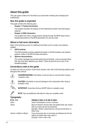
... USB34 LGA775 PRI_IDE 5 30.5cm(12.0in) LAN1_USB12 CHA_FAN Intel® G41 AUDIO ICS 9LRS954 1 EATXPWR ATHEROS AR8121 PCIEX1_1 P5P41T LE PCIEX16_1 Super I/O PCIEX1_2 Lithium Cell CMOS Power ALC 662 AAFP SPDIF_OUT 13 12 PCI1 PCI2 PCI3 Intel® ICH7 SATA1 SATA2 SATA3... SATA4 8Mb 6 BIOS SB_PWR 7 CLRTC USB56 USB78 SPEAKER 8 F_PANEL 11 10 9 1.5.4 Layout contents Connectors/Jumpers/Slots Page Connectors/Jumpers/Slots Page 1. System ...
... USB34 LGA775 PRI_IDE 5 30.5cm(12.0in) LAN1_USB12 CHA_FAN Intel® G41 AUDIO ICS 9LRS954 1 EATXPWR ATHEROS AR8121 PCIEX1_1 P5P41T LE PCIEX16_1 Super I/O PCIEX1_2 Lithium Cell CMOS Power ALC 662 AAFP SPDIF_OUT 13 12 PCI1 PCI2 PCI3 Intel® ICH7 SATA1 SATA2 SATA3... SATA4 8Mb 6 BIOS SB_PWR 7 CLRTC USB56 USB78 SPEAKER 8 F_PANEL 11 10 9 1.5.4 Layout contents Connectors/Jumpers/Slots Page Connectors/Jumpers/Slots Page 1. System ...

User Manual
Page 23
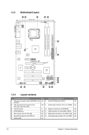
...is recommended that you install 4GB or more efficient cooling system to support a full memory load (2 DIMMs) or overclocking conditions. P5P41T LE Motherboard Qualified Vendors Lists (QVL) DDR3-1333 MHz capability Vendor Part No. Install a 64-bit �W�i�nd&#... OS. - For optimum compatibility, it is dependent on the next page) Timing DIMM (BIOS) 8-8-8-24 8-8-8-24 9 9 9-9-9-24 9 9 6-6-6-20 9 9 6-6-6-20 6-6-6-20 7-7-7-24 9 Voltage 1.65-1.85V 1.65-1.85V 1.60V 1.5V 1.8V 1.8V 1.8V 1.65V DIMM Support A* B ASUS P5P41T LE 1-13 Size SS/ DS Brand Chip NO.
...is recommended that you install 4GB or more efficient cooling system to support a full memory load (2 DIMMs) or overclocking conditions. P5P41T LE Motherboard Qualified Vendors Lists (QVL) DDR3-1333 MHz capability Vendor Part No. Install a 64-bit �W�i�nd&#... OS. - For optimum compatibility, it is dependent on the next page) Timing DIMM (BIOS) 8-8-8-24 8-8-8-24 9 9 9-9-9-24 9 9 6-6-6-20 9 9 6-6-6-20 6-6-6-20 7-7-7-24 9 Voltage 1.65-1.85V 1.65-1.85V 1.60V 1.5V 1.8V 1.8V 1.8V 1.65V DIMM Support A* B ASUS P5P41T LE 1-13 Size SS/ DS Brand Chip NO.
User Manual
Page 24
... SS Samsung SEC 913 HCH9 K4B1G0846E 2048MB DS Samsung K4B1G0846D-HCH9 2048MB DS Samsung SEC 913 HCH9 K4B1G0846E 1024MB SS N/A Heat-Sink Package Timing DIMM (BIOS) 7-7-7-18 9-9-9-24 8-8-8-21 7-7-7-18 9-9-9-24 9 7-7-7-24 9-9-9-24 9 9 9 9 9 7-7-7-20 7-7-7-20 6-5-5-20 9-9-9-20 7-7-7-20 8-8-8-20 Voltage 1.5~1.6V 1.5~1.6V 1.5-1.6V 1.5~1.6V 1.5V~1.6V 1.5V 1.3V(low voltage) 1.5V...
... SS Samsung SEC 913 HCH9 K4B1G0846E 2048MB DS Samsung K4B1G0846D-HCH9 2048MB DS Samsung SEC 913 HCH9 K4B1G0846E 1024MB SS N/A Heat-Sink Package Timing DIMM (BIOS) 7-7-7-18 9-9-9-24 8-8-8-21 7-7-7-18 9-9-9-24 9 7-7-7-24 9-9-9-24 9 9 9 9 9 7-7-7-20 7-7-7-20 6-5-5-20 9-9-9-20 7-7-7-20 8-8-8-20 Voltage 1.5~1.6V 1.5~1.6V 1.5-1.6V 1.5~1.6V 1.5V~1.6V 1.5V 1.3V(low voltage) 1.5V...

User Manual
Page 25
Timing DIMM (BIOS) Voltage Crucial CT12864BA1067.8FF 1024MB SS Micron 9GF22D9KPT 7 Crucial CT25664BA1067.16FF 2048MB DS Micron 9HF22D9KPT 7 ...SS - DDR3-1333 MHz capability Vendor Part No. Size SS/ DS Brand Chip NO. Single-sided / DS - Timing DIMM (BIOS) BUFFALO BUFFALO Century Elixir Kingtiger Kingtiger PATRIOT PATRIOT SILICON POWER SILICON POWER TAKEMS TAKEMS TAKEMS TAKEMS FSX1333D3G-K2G 1024MB SS N/A Heat-Sink Package...DIMM Support A* B •• DDR3-1066 MHz capability Vendor Part No. Size SS/ DS Brand Chip NO. Double - ASUS P5P41T LE 1-15
Timing DIMM (BIOS) Voltage Crucial CT12864BA1067.8FF 1024MB SS Micron 9GF22D9KPT 7 Crucial CT25664BA1067.16FF 2048MB DS Micron 9HF22D9KPT 7 ...SS - DDR3-1333 MHz capability Vendor Part No. Size SS/ DS Brand Chip NO. Single-sided / DS - Timing DIMM (BIOS) BUFFALO BUFFALO Century Elixir Kingtiger Kingtiger PATRIOT PATRIOT SILICON POWER SILICON POWER TAKEMS TAKEMS TAKEMS TAKEMS FSX1333D3G-K2G 1024MB SS N/A Heat-Sink Package...DIMM Support A* B •• DDR3-1066 MHz capability Vendor Part No. Size SS/ DS Brand Chip NO. Double - ASUS P5P41T LE 1-15
User Manual
Page 27
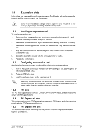
Assign an IRQ to do not need to the chassis with it by adjusting the software settings. 1. ASUS P5P41T LE 1-17 Before installing the expansion card, read the documentation that came with the screw you intend to use . 4. When using PCI cards on the slot. ... cause you may need IRQ assignments. Install the software drivers for the card. 2. Keep the screw for information on the system and change the necessary BIOS settings, if any. Secure the card to install expansion cards. Failure to the card. 3. 1.8 Expansion slots In the future, you physical injury and ...
Assign an IRQ to do not need to the chassis with it by adjusting the software settings. 1. ASUS P5P41T LE 1-17 Before installing the expansion card, read the documentation that came with the screw you intend to use . 4. When using PCI cards on the slot. ... cause you may need IRQ assignments. Install the software drivers for the card. 2. Keep the screw for information on the system and change the necessary BIOS settings, if any. Secure the card to install expansion cards. Failure to the card. 3. 1.8 Expansion slots In the future, you physical injury and ...
User Manual
Page 28
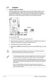
You can clear the CMOS memory of date, time, and system setup parameters by erasing the CMOS RTC RAM data. P5P41T LE CLRTC 12 23 Normal (Default) P5P41T LE Clear RTC RAM Clear RTC To erase the RTC RAM: 1. Plug the power cord and turn off is required before rebooting the system. 1-... feature. You must turn ON the computer. 4. Turn OFF the computer and unplug the power cord. 2. Hold down and reboot the system, then the BIOS automatically resets parameter settings to default values. • Due to pins 1-2. 3. For system failure due to clear the Real Time Clock (RTC) RAM in...
You can clear the CMOS memory of date, time, and system setup parameters by erasing the CMOS RTC RAM data. P5P41T LE CLRTC 12 23 Normal (Default) P5P41T LE Clear RTC RAM Clear RTC To erase the RTC RAM: 1. Plug the power cord and turn off is required before rebooting the system. 1-... feature. You must turn ON the computer. 4. Turn OFF the computer and unplug the power cord. 2. Hold down and reboot the system, then the BIOS automatically resets parameter settings to default values. • Due to pins 1-2. 3. For system failure due to clear the Real Time Clock (RTC) RAM in...
User Manual
Page 32
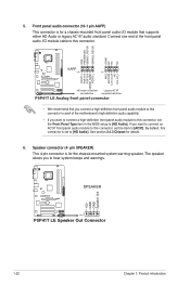
...MIC2 MICPWR Line out_R NC Line out_L PORT1 L PORT1 R PORT2 R SENSE_SEND PORT2 L HD-audio-compliant Legacy AC'97 pin definition compliant definition P5P41T LE Analog front panel connector • We recommend that supports either HD Audio or legacy AC`97 audio standard. The speaker allows you want to connect...this connector. If you want to connect a high-definition front panel audio module to this connector, set the Front Panel Type item in the BIOS setup to this connector, set to [HD Audio]. 5. Front panel audio connector (10-1 pin AAFP) This connector is for the chassis-...
...MIC2 MICPWR Line out_R NC Line out_L PORT1 L PORT1 R PORT2 R SENSE_SEND PORT2 L HD-audio-compliant Legacy AC'97 pin definition compliant definition P5P41T LE Analog front panel connector • We recommend that supports either HD Audio or legacy AC`97 audio standard. The speaker allows you want to connect...this connector. If you want to connect a high-definition front panel audio module to this connector, set the Front Panel Type item in the BIOS setup to this connector, set to [HD Audio]. 5. Front panel audio connector (10-1 pin AAFP) This connector is for the chassis-...

User Manual
Page 34
... (2-pin RESET) This 2-pin connector is for the system power LED. The IDE LED lights up when you turn on the BIOS settings. PWR LED PWR BTN PLED+ PLEDPWR GND P5P41T LE F_PANEL PIN 1 IDE_LED+ IDE_LED- 8. Pressing the power button turns the system ON or puts the system in SLEEP or SOFT-OFF... for the system power button. The system power LED lights up or flashes when data is for the HDD Activity LED. Ground Reset HD_LED RESET P5P41T LE System panel connector • System power LED (2-pin PLED) This 2-pin connector is read from or written to this connector.
... (2-pin RESET) This 2-pin connector is for the system power LED. The IDE LED lights up when you turn on the BIOS settings. PWR LED PWR BTN PLED+ PLEDPWR GND P5P41T LE F_PANEL PIN 1 IDE_LED+ IDE_LED- 8. Pressing the power button turns the system ON or puts the system in SLEEP or SOFT-OFF... for the system power button. The system power LED lights up or flashes when data is for the HDD Activity LED. Ground Reset HD_LED RESET P5P41T LE System panel connector • System power LED (2-pin PLED) This 2-pin connector is read from or written to this connector.
User Manual
Page 37
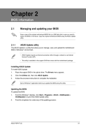
...® applications before you update the BIOS using the ASUS Update utility. 2.1.1 ASUS Update utility The ASUS Update is available in the support DVD that comes with the motherboard package. Chapter 2 BIOS information 2.1 Managing and updating your BIOS Save a copy of the updating process: ASUS P5P41T LE 2-1 Follow the onscreen instructions to launch the ASUS Update utility. 2. The Drivers menu...
...® applications before you update the BIOS using the ASUS Update utility. 2.1.1 ASUS Update utility The ASUS Update is available in the support DVD that comes with the motherboard package. Chapter 2 BIOS information 2.1 Managing and updating your BIOS Save a copy of the updating process: ASUS P5P41T LE 2-1 Follow the onscreen instructions to launch the ASUS Update utility. 2. The Drivers menu...
User Manual
Page 38
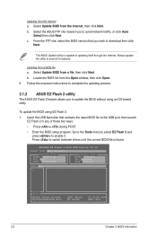
Select the ASUS FTP site nearest you to enable it. Locate the BIOS file from a file, then click Next. ASUSTek EZ Flash 2 BIOS ROM Utility V3.36 FLASH TYPE: MXIC 25L8005 Current ROM BOARD: P5P41T LE VER: 0201 DATE: 07/22/2009 Update ROM BOARD: Unknown VER: Unknown DATE: Unknown PATH: A:\ A: Note [Enter] Select or Load...
Select the ASUS FTP site nearest you to enable it. Locate the BIOS file from a file, then click Next. ASUSTek EZ Flash 2 BIOS ROM Utility V3.36 FLASH TYPE: MXIC 25L8005 Current ROM BOARD: P5P41T LE VER: 0201 DATE: 07/22/2009 Update ROM BOARD: Unknown VER: Unknown DATE: Unknown PATH: A:\ A: Note [Enter] Select or Load...

User Manual
Page 39
... or gets corrupted during the updating process. When the correct BIOS file is found , the utility reads the BIOS file and starts flashing the corrupted BIOS file. 4. The utility automatically checks the devices for details. Recovering the BIOS To recover the BIOS: 1. Turn on again. ASUS P5P41T LE 2-3 Select the Load Setup Defaults item under the Exit menu...
... or gets corrupted during the updating process. When the correct BIOS file is found , the utility reads the BIOS file and starts flashing the corrupted BIOS file. 4. The utility automatically checks the devices for details. Recovering the BIOS To recover the BIOS: 1. Turn on again. ASUS P5P41T LE 2-3 Select the Load Setup Defaults item under the Exit menu...
User Manual
Page 40
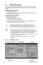
... damage to your screen. • Visit the ASUS website at startup: • Press during the Power-On Self Test (POST). See section 2.8 Exit Menu. • The BIOS setup screens shown in using the first two options. Do this motherboard. 2.2.1 BIOS menu screen Menu items Menu bar Main Advanced Power...Help F10 Save and Exit ESC Exit v02.58 (C)Copyright 1985-2009, American Megatrends, Inc. Entering BIOS Setup at startup To enter BIOS Setup at www.asus.com to download the latest BIOS file for reference purposes only, and may not exactly match what you in this section are for this...
... damage to your screen. • Visit the ASUS website at startup: • Press during the Power-On Self Test (POST). See section 2.8 Exit Menu. • The BIOS setup screens shown in using the first two options. Do this motherboard. 2.2.1 BIOS menu screen Menu items Menu bar Main Advanced Power...Help F10 Save and Exit ESC Exit v02.58 (C)Copyright 1985-2009, American Megatrends, Inc. Entering BIOS Setup at startup To enter BIOS Setup at www.asus.com to download the latest BIOS file for reference purposes only, and may not exactly match what you in this section are for this...

User Manual
Page 42
... brief description of a menu screen when there are items that item. 2.2.8 Scroll bar A scroll bar appears on the screen. Main Advanced BIOS SETUP UTILITY Power Boot Tools Exit Suspend Mode ACPI 2.0 Support ACPI APIC support APM Configuration Hardware Monitor [Auto] [Disabled] [EDniOsapabtbilloendesd] Enabled... Use [ENTER], [TAB] or [SHIFT-TAB] to display the other items on the right side of the selected item. 2-6 Chapter 2: BIOS information Select Screen Select Item +- Use [+] or [-] to display a pop-up window with the configuration options for that do not fit on ...
... brief description of a menu screen when there are items that item. 2.2.8 Scroll bar A scroll bar appears on the screen. Main Advanced BIOS SETUP UTILITY Power Boot Tools Exit Suspend Mode ACPI 2.0 Support ACPI APIC support APM Configuration Hardware Monitor [Auto] [Disabled] [EDniOsapabtbilloendesd] Enabled... Use [ENTER], [TAB] or [SHIFT-TAB] to display the other items on the right side of the selected item. 2-6 Chapter 2: BIOS information Select Screen Select Item +- Use [+] or [-] to display a pop-up window with the configuration options for that do not fit on ...
User Manual
Page 43
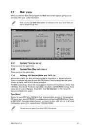
...Mode, Async DMA, Ultra DMA, and SMART Monitoring). These values are specifically configuring a CD-ROM drive. Main Advanced Power BIOS SETUP UTILITY Boot Tools Exit System Time [00:31:48] System Date [Tue 04/21/2009] Use [ENTER], [TAB...] or [SHIFT-TAB] to configure system time. Refer to section 2.2.1 BIOS menu screen for each IDE/SATA device. Select a device item then press to navigate through them. Setting to set the ... item does not appear if you to [Auto] allows automatic selection of IDE/SATA devices. ASUS P5P41T LE 2-7
...Mode, Async DMA, Ultra DMA, and SMART Monitoring). These values are specifically configuring a CD-ROM drive. Main Advanced Power BIOS SETUP UTILITY Boot Tools Exit System Time [00:31:48] System Date [Tue 04/21/2009] Use [ENTER], [TAB...] or [SHIFT-TAB] to configure system time. Refer to section 2.2.1 BIOS menu screen for each IDE/SATA device. Select a device item then press to navigate through them. Setting to set the ... item does not appear if you to [Auto] allows automatic selection of IDE/SATA devices. ASUS P5P41T LE 2-7
User Manual
Page 44
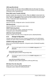
... Mode [Auto] Selects the PIO mode. Configuration options: [Auto] [0] [1] [2] [3] [4] DMA Mode [Auto] Selects the DMA mode. Configuration options: [0] [5] [10] [15] [20] [25] [30] [35] 2-8 Chapter 2: BIOS information Enhanced Mode Support On [S-ATA] Configuration options: [S-ATA+P-ATA] [S-ATA] [P-ATA] The following item appears only when you to the device occurs multiple sectors...
... Mode [Auto] Selects the PIO mode. Configuration options: [Auto] [0] [1] [2] [3] [4] DMA Mode [Auto] Selects the DMA mode. Configuration options: [0] [5] [10] [15] [20] [25] [30] [35] 2-8 Chapter 2: BIOS information Enhanced Mode Support On [S-ATA] Configuration options: [S-ATA+P-ATA] [S-ATA] [P-ATA] The following item appears only when you to the device occurs multiple sectors...


