
User Manual
Page 1
P5P41C Motherboard
P5P41C Motherboard

User Manual
Page 3
Contents Notices...vi Safety information vii About this guide vii P5P41C specifications summary ix Chapter 1: Product introduction 1.1 Welcome 1-1 1.2 Package contents 1-1 1.3 Special features 1-1 1.3.1 Product highlights 1-1 1.3.2 Innovative ASUS features 1-2 1.4 Before you proceed 1-4 1.5 Motherboard overview 1-5 1.5.1 Placement direction 1-5 1.5.2 Screw holes 1-5 1.5.3 Motherboard layout 1-6 1.5.4 Layout contents 1-6 1.6 Central Processing Unit (CPU 1-7 1.6.1 Installing the CPU 1-7 1.6.2 Installing the CPU heatsink and fan 1-10 1.6.3 Uninstalling...
Contents Notices...vi Safety information vii About this guide vii P5P41C specifications summary ix Chapter 1: Product introduction 1.1 Welcome 1-1 1.2 Package contents 1-1 1.3 Special features 1-1 1.3.1 Product highlights 1-1 1.3.2 Innovative ASUS features 1-2 1.4 Before you proceed 1-4 1.5 Motherboard overview 1-5 1.5.1 Placement direction 1-5 1.5.2 Screw holes 1-5 1.5.3 Motherboard layout 1-6 1.5.4 Layout contents 1-6 1.6 Central Processing Unit (CPU 1-7 1.6.1 Installing the CPU 1-7 1.6.2 Installing the CPU heatsink and fan 1-10 1.6.3 Uninstalling...
User Manual
Page 6
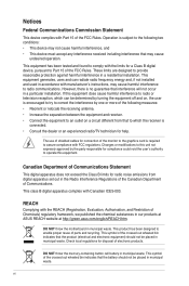
...instructions, may cause undesired operation. These limits are designed to enable proper reuse of parts and recycling. DO NOT throw the motherboard in municipal waste. Changes or modifications to this unit not expressly approved by one or more of the following two conditions:... residential installation. This product has been designed to provide reasonable protection against harmful interference in our products at ASUS REACH website at http://green.asus.com/english/REACH.htm. Canadian Department of Communications Statement This digital apparatus does not exceed the Class B ...
...instructions, may cause undesired operation. These limits are designed to enable proper reuse of parts and recycling. DO NOT throw the motherboard in municipal waste. Changes or modifications to this unit not expressly approved by one or more of the following two conditions:... residential installation. This product has been designed to provide reasonable protection against harmful interference in our products at ASUS REACH website at http://green.asus.com/english/REACH.htm. Canadian Department of Communications Statement This digital apparatus does not exceed the Class B ...
User Manual
Page 7
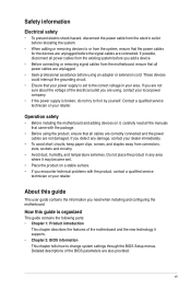
...change system settings through the BIOS Setup menus. Detailed descriptions of the BIOS parameters are not sure about the voltage of the motherboard and the new technology it by yourself. These devices could interrupt the grounding circuit. • Ensure that all power cables ... parts: • Chapter 1: Product introduction This chapter describes the features of the electrical outlet you need when installing and configuring the motherboard. If possible, disconnect all power cables from the existing system before you encounter technical problems with the package. • Before using ...
...change system settings through the BIOS Setup menus. Detailed descriptions of the BIOS parameters are not sure about the voltage of the motherboard and the new technology it by yourself. These devices could interrupt the grounding circuit. • Ensure that all power cables ... parts: • Chapter 1: Product introduction This chapter describes the features of the electrical outlet you need when installing and configuring the motherboard. If possible, disconnect all power cables from the existing system before you encounter technical problems with the package. • Before using ...
User Manual
Page 11
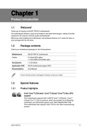
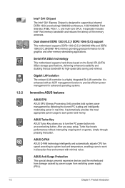
...™ 2 Extreme / Core™ 2 Quad/ Core™ 2 Duo processors, which are excellent for buying an ASUS® P5P41C motherboard! ASUS P5P41C 1-1 Thank you start installing the motherboard, and hardware devices on it another standout in the long line of ASUS quality motherboards! Before you for multitasking, multimedia, and enthusiastic gamers with the list below. 1.2 Package contents Check your...
...™ 2 Extreme / Core™ 2 Quad/ Core™ 2 Duo processors, which are excellent for buying an ASUS® P5P41C motherboard! ASUS P5P41C 1-1 Thank you start installing the motherboard, and hardware devices on it another standout in the long line of ASUS quality motherboards! Before you for multitasking, multimedia, and enthusiastic gamers with the list below. 1.2 Package contents Check your...
User Manual
Page 12
... dual-channel DDR3 1333 (overclocking)/1066/800 architecture, 1333/1066/800 Front Side Bus (FSB), PCIe 1.1, and mutli-core CPUs. ASUS Anti-Surge Protection This special design prevents expensive devices and the motherboard from switching power supply (PSU). 1-2 Chapter 1: Product introduction It especially includes Intel® Fast memory bandwidth and reduces the...
... dual-channel DDR3 1333 (overclocking)/1066/800 architecture, 1333/1066/800 Front Side Bus (FSB), PCIe 1.1, and mutli-core CPUs. ASUS Anti-Surge Protection This special design prevents expensive devices and the motherboard from switching power supply (PSU). 1-2 Chapter 1: Product introduction It especially includes Intel® Fast memory bandwidth and reduces the...
User Manual
Page 13
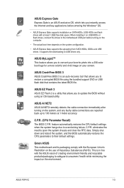
... only. feature automatically restores the CPU default settings when the system hangs due to their default settings. Green ASUS This motherboard and its packaging comply with the European Union's Restriction on the system configuration. • ASUS Express Gate supports file uploading from SATA HDDs, ODDs and USB drives. When installing it on USB... faulty cable connections are reported back up to safeguard consumers' health while minimizing the impact on SATA HDDs, USB HDDs and flash drives with the ASUS vision of Hazardous Substances (RoHS). C.P.R. ASUS P5P41C 1-3
... only. feature automatically restores the CPU default settings when the system hangs due to their default settings. Green ASUS This motherboard and its packaging comply with the European Union's Restriction on the system configuration. • ASUS Express Gate supports file uploading from SATA HDDs, ODDs and USB drives. When installing it on USB... faulty cable connections are reported back up to safeguard consumers' health while minimizing the impact on SATA HDDs, USB HDDs and flash drives with the ASUS vision of Hazardous Substances (RoHS). C.P.R. ASUS P5P41C 1-3

User Manual
Page 14
... plugging in the bag that came with the component. • Before you install or remove any motherboard component. Onboard LED The motherboard comes with a standby power LED that lights up to the motherboard, peripherals, or components. P5P41C SB_PWR P5P41C Onboard LED ON OFF Standby Power Powered Off 1-4 Chapter 1: Product introduction Failure to do so may...
... plugging in the bag that came with the component. • Before you install or remove any motherboard component. Onboard LED The motherboard comes with a standby power LED that lights up to the motherboard, peripherals, or components. P5P41C SB_PWR P5P41C Onboard LED ON OFF Standby Power Powered Off 1-4 Chapter 1: Product introduction Failure to do so may...

User Manual
Page 15
... unplug the power cord before installing or removing the motherboard. Do not overtighten the screws! Place this side towards the rear of the chassis P5P41C ASUS P5P41C 1-5 Failure to do so can damage the motherboard. Ensure that the motherboard fits into it. 1.5 Motherboard overview Before you install the motherboard, study the configuration of your chassis to the chassis...
... unplug the power cord before installing or removing the motherboard. Do not overtighten the screws! Place this side towards the rear of the chassis P5P41C ASUS P5P41C 1-5 Failure to do so can damage the motherboard. Ensure that the motherboard fits into it. 1.5 Motherboard overview Before you install the motherboard, study the configuration of your chassis to the chassis...
User Manual
Page 16
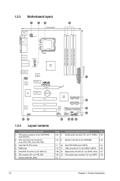
1.5.3 Motherboard layout 1 2 3 4 20.8cm(8.2in) KBMS ATX12V COM1 LPT DDR3_A1 (64bit, 240-pin module) DDR2_A1 (64bit, 240-pin module) DDR3_B1 (64bit, 240-pin module) DDR2_B1 (64bit, 240-pin module) LGA775 USB34 CPU_FAN LAN1_USB12 CHA_FAN Intel® G41 30.5cm(12.0in) AUDIO EATXPWR ICS 9LRS954 1 AAFP RTL 8112L PCIEX1_1 P5P41C PCIEX16 Super I/O PCIEX1_2...
1.5.3 Motherboard layout 1 2 3 4 20.8cm(8.2in) KBMS ATX12V COM1 LPT DDR3_A1 (64bit, 240-pin module) DDR2_A1 (64bit, 240-pin module) DDR3_B1 (64bit, 240-pin module) DDR2_B1 (64bit, 240-pin module) LGA775 USB34 CPU_FAN LAN1_USB12 CHA_FAN Intel® G41 30.5cm(12.0in) AUDIO EATXPWR ICS 9LRS954 1 AAFP RTL 8112L PCIEX1_1 P5P41C PCIEX16 Super I/O PCIEX1_2...

User Manual
Page 17
.../removal, or misplacement/loss/incorrect removal of the motherboard, ensure that the cam box is facing towards you see any damage to ensure system stability. • Upon purchase of the PnP cap. ASUS P5P41C 1-7 Contact your left. Locate the CPU socket...the cap after installing the motherboard. ASUS will process Return Merchandise Authorization (RMA) requests only if the motherboard comes with the Intel® Enhanced Intel SpeedStep® Technology (EIST) and Hyper-Threading Technology. 1.6.1 Installing the CPU To install a CPU: 1. P5P41C P5P41C CPU socket 775 Before ...
.../removal, or misplacement/loss/incorrect removal of the motherboard, ensure that the cam box is facing towards you see any damage to ensure system stability. • Upon purchase of the PnP cap. ASUS P5P41C 1-7 Contact your left. Locate the CPU socket...the cap after installing the motherboard. ASUS will process Return Merchandise Authorization (RMA) requests only if the motherboard comes with the Intel® Enhanced Intel SpeedStep® Technology (EIST) and Hyper-Threading Technology. 1.6.1 Installing the CPU To install a CPU: 1. P5P41C P5P41C CPU socket 775 Before ...
User Manual
Page 20
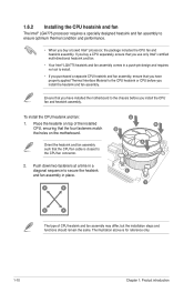
... to secure the heatsink and fan assembly in place. A B A B B A 1 1 B A The type of the installed CPU, ensuring that the four fasteners match the holes on the motherboard. To install the CPU heatsink and fan: 1. Orient the heatsink and fan assembly such that the CPU fan cable is for reference only. 1-10 Chapter... a push-pin design and requires no tool to install. • If you purchased a separate CPU heatsink and fan assembly, ensure that you have installed the motherboard to the chassis before you install the heatsink and fan assembly.
... to secure the heatsink and fan assembly in place. A B A B B A 1 1 B A The type of the installed CPU, ensuring that the four fasteners match the holes on the motherboard. To install the CPU heatsink and fan: 1. Orient the heatsink and fan assembly such that the CPU fan cable is for reference only. 1-10 Chapter... a push-pin design and requires no tool to install. • If you purchased a separate CPU heatsink and fan assembly, ensure that you have installed the motherboard to the chassis before you install the heatsink and fan assembly.
User Manual
Page 21
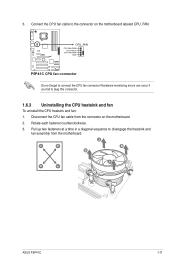
... to the connector on the motherboard. 2. Disconnect the CPU fan cable from the motherboard. Hardware monitoring errors can occur if you fail to connect the CPU fan connector! Connect the CPU fan cable to disengage the heatsink and fan assembly from the connector on the motherboard labeled CPU_FAN. A A B B B A B A ASUS P5P41C 1-11 3. Rotate each fastener counterclockwise...
... to the connector on the motherboard. 2. Disconnect the CPU fan cable from the motherboard. Hardware monitoring errors can occur if you fail to connect the CPU fan connector! Connect the CPU fan cable to disengage the heatsink and fan assembly from the connector on the motherboard labeled CPU_FAN. A A B B B A B A ASUS P5P41C 1-11 3. Rotate each fastener counterclockwise...
User Manual
Page 22
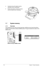
The figure illustrates the location of the DIMM sockets: DDR3_A1 DDR2_A1 DDR3_B1 DDR2_B1 P5P41C P5P41C 240-pin DIMM sockets Channel Channel A Channel B Sockets DDR3_A1 and DDR2_A1 DDR3_B1 and DDR2_B1 1-12 Chapter 1: Product introduction Rotate each fastener clockwise to ensure correct orientation when reinstalling. 1.7 System memory 1.7.1 Overview The motherboard comes with two Double Data Rate 3 (DDR3) and two Double Data Rate 3 (DDR2) Dual Inline Memory Modules (DIMM) sockets. 4. Carefully remove the heatsink and fan assembly from the motherboard. 5.
The figure illustrates the location of the DIMM sockets: DDR3_A1 DDR2_A1 DDR3_B1 DDR2_B1 P5P41C P5P41C 240-pin DIMM sockets Channel Channel A Channel B Sockets DDR3_A1 and DDR2_A1 DDR3_B1 and DDR2_B1 1-12 Chapter 1: Product introduction Rotate each fastener clockwise to ensure correct orientation when reinstalling. 1.7 System memory 1.7.1 Overview The motherboard comes with two Double Data Rate 3 (DDR3) and two Double Data Rate 3 (DDR2) Dual Inline Memory Modules (DIMM) sockets. 4. Carefully remove the heatsink and fan assembly from the motherboard. 5.
User Manual
Page 23
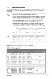
...• • 7 - • • - - • • - - • • - - • • 7-7-7-20 - • • - - • • - - • • ASUS P5P41C 1-13 Any excess memory from the same vendor. • Due to the memory address limitation on 32-bit Windows® OS, when you want to... stability, use a more efficient cooling system to support a full memory load (2 DIMMs) or overclocking conditions. P5P41C Motherboard Qualified Vendors Lists (QVL) DDR3-1066 MHz capability Vendor Part No. For effective use DDR2 and DDR3 memory ...
...• • 7 - • • - - • • - - • • - - • • 7-7-7-20 - • • - - • • - - • • ASUS P5P41C 1-13 Any excess memory from the same vendor. • Due to the memory address limitation on 32-bit Windows® OS, when you want to... stability, use a more efficient cooling system to support a full memory load (2 DIMMs) or overclocking conditions. P5P41C Motherboard Qualified Vendors Lists (QVL) DDR3-1066 MHz capability Vendor Part No. For effective use DDR2 and DDR3 memory ...
User Manual
Page 29
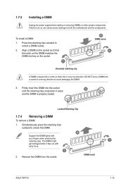
... the DIMM. 2 Support the DIMM lightly with extra force. 1 2. Remove the DIMM from the socket. Locked Retaining Clip 1.7.4 Removing a DIMM To remove a DIMM: 1. DIMM notch ASUS P5P41C 1-19 Simultaneously press the retaining clips outward to avoid damaging the DIMM. 3. To install a DIMM: 1. Failure to do so can cause severe damage to unlock... one direction. 1.7.3 Installing a DIMM Unplug the power supply before adding or removing DIMMs or other system components. Press the retaining clips outward to both the motherboard and the components.
... the DIMM. 2 Support the DIMM lightly with extra force. 1 2. Remove the DIMM from the socket. Locked Retaining Clip 1.7.4 Removing a DIMM To remove a DIMM: 1. DIMM notch ASUS P5P41C 1-19 Simultaneously press the retaining clips outward to avoid damaging the DIMM. 3. To install a DIMM: 1. Failure to do so can cause severe damage to unlock... one direction. 1.7.3 Installing a DIMM Unplug the power supply before adding or removing DIMMs or other system components. Press the retaining clips outward to both the motherboard and the components.
User Manual
Page 30
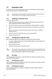
... card that the cards do so may need IRQ assignments. 1.8 Expansion slots In the future, you may cause you physical injury and damage motherboard components. 1.8.1 Installing an expansion card To install an expansion card: 1. Failure to do not need to the chassis with the PCI Express ... following sub‑sections describe the slots and the expansion cards that you removed earlier. 6. Remove the system unit cover (if your motherboard is completely seated on shared slots, ensure that the drivers support "Share IRQ" or that complies with the screw you intend to the card...
... card that the cards do so may need IRQ assignments. 1.8 Expansion slots In the future, you may cause you physical injury and damage motherboard components. 1.8.1 Installing an expansion card To install an expansion card: 1. Failure to do not need to the chassis with the PCI Express ... following sub‑sections describe the slots and the expansion cards that you removed earlier. 6. Remove the system unit cover (if your motherboard is completely seated on shared slots, ensure that the drivers support "Share IRQ" or that complies with the screw you intend to the card...
User Manual
Page 33
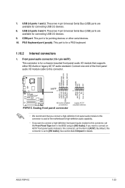
... 1 PIN 1 MIC2 MICPWR Line out_R NC Line out_L PORT1 L PORT1 R PORT2 R SENSE_SEND PORT2 L HD-audio-compliant pin definition P5P41C Analog front panel connector Legacy AC'97 compliant definition • We recommend that supports either HD Audio or legacy AC`97 audio standard...-definition front panel audio module to this connector to avail of the motherboard's high-definition audio capability. • If you want to connect a high-definition front panel audio module to this connector, set the item to [HD Audio]. ASUS P5P41C 1-23 These two 4-pin Universal Serial Bus (USB) ports are...
... 1 PIN 1 MIC2 MICPWR Line out_R NC Line out_L PORT1 L PORT1 R PORT2 R SENSE_SEND PORT2 L HD-audio-compliant pin definition P5P41C Analog front panel connector Legacy AC'97 compliant definition • We recommend that supports either HD Audio or legacy AC`97 audio standard...-definition front panel audio module to this connector to avail of the motherboard's high-definition audio capability. • If you want to connect a high-definition front panel audio module to this connector, set the item to [HD Audio]. ASUS P5P41C 1-23 These two 4-pin Universal Serial Bus (USB) ports are...

User Manual
Page 34
...-1 pin PRI_IDE) The onboard IDE connector is for Ultra DMA 133/100/66 IDE devices. P5P41C PRI_IDE P5P41C IDE connector PIN1 NOTE:Orient the red markings on the Ultra DMA cable connector. Connect the blue connector to the motherboard's IDE connector, then select one of device(s) Master Slave Master Slave Cable connector Black...
...-1 pin PRI_IDE) The onboard IDE connector is for Ultra DMA 133/100/66 IDE devices. P5P41C PRI_IDE P5P41C IDE connector PIN1 NOTE:Orient the red markings on the Ultra DMA cable connector. Connect the blue connector to the motherboard's IDE connector, then select one of device(s) Master Slave Master Slave Cable connector Black...
User Manual
Page 36
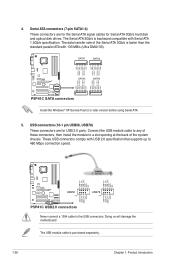
... USB 2.0 specification that supports up to the USB connectors. USB+5V USB_P8USB_P8+ GND NC USB+5V USB_P6USB_P6+ GND NC P5P41C USB56 PIN 1 USB78 PIN 1 USB+5V USB_P7USB_P7+ GND USB+5V USB_P5USB_P5+ GND P5P41C USB2.0 connectors Never connect a 1394 cable to 480 Mbps connection speed. The Serial ATA 3Gb/s is purchased separately. 1-26... at the back of the Serial ATA 3Gb/s is faster than the standard parallel ATA with Serial ATA 1.5Gb/s specification. Doing so will damage the motherboard! 4. The USB module cable is backward compatible with 133 MB/s (Ultra DMA133).
... USB 2.0 specification that supports up to the USB connectors. USB+5V USB_P8USB_P8+ GND NC USB+5V USB_P6USB_P6+ GND NC P5P41C USB56 PIN 1 USB78 PIN 1 USB+5V USB_P7USB_P7+ GND USB+5V USB_P5USB_P5+ GND P5P41C USB2.0 connectors Never connect a 1394 cable to 480 Mbps connection speed. The Serial ATA 3Gb/s is purchased separately. 1-26... at the back of the Serial ATA 3Gb/s is faster than the standard parallel ATA with Serial ATA 1.5Gb/s specification. Doing so will damage the motherboard! 4. The USB module cable is backward compatible with 133 MB/s (Ultra DMA133).


