User Manual
Page 5
...® RAID configurations 5-2 5.1.4 LSI Logic Embedded SATA RAID Setup Utility ...... 5-13 Chapter 6: Driver installation 6.1 RAID driver installation 6-1 6.1.1 Creating a RAID driver disk 6-1 6.1.2 Installing the Intel® ICH7R RAID controller driver .... 6-3 6.2 LAN driver installation 6-7 6.2.1 Windows® 2000/2003 Server 6-7 6.2.2 Red Hat® Linux 9.0 6-9 6.3 VGA driver installation 6-11 6.3.1 Windows® 2000 Server 6-11 6.3.2 Windows® 2003 Server 6-12 6.3.3 Red...
...® RAID configurations 5-2 5.1.4 LSI Logic Embedded SATA RAID Setup Utility ...... 5-13 Chapter 6: Driver installation 6.1 RAID driver installation 6-1 6.1.1 Creating a RAID driver disk 6-1 6.1.2 Installing the Intel® ICH7R RAID controller driver .... 6-3 6.2 LAN driver installation 6-7 6.2.1 Windows® 2000/2003 Server 6-7 6.2.2 Red Hat® Linux 9.0 6-9 6.3 VGA driver installation 6-11 6.3.1 Windows® 2000 Server 6-11 6.3.2 Windows® 2003 Server 6-12 6.3.3 Red...
User Manual
Page 8
... description of the standard package. Detailed descriptions of the BIOS parameters are not part of the switches, jumpers, and connectors on RAID, LAN and VGA driver installation for this motherboard. • A p p e n d i x: R e f e r e n c e i n f o r m a t i o n This appendix includes additional information ... supports. • Chapter 2: Hardware information This chapter lists the hardware setup procedures that may refer to the ASUS contact information. 2. Optional documentation Your product package may include optional documentation, such as warranty flyers, that you need...
... description of the standard package. Detailed descriptions of the BIOS parameters are not part of the switches, jumpers, and connectors on RAID, LAN and VGA driver installation for this motherboard. • A p p e n d i x: R e f e r e n c e i n f o r m a t i o n This appendix includes additional information ... supports. • Chapter 2: Hardware information This chapter lists the hardware setup procedures that may refer to the ASUS contact information. 2. Optional documentation Your product package may include optional documentation, such as warranty flyers, that you need...
User Manual
Page 11
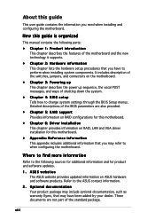
xi P5MT-M specifications summary Internal connectors Power Requirement Form Factor Support CD contents 1 x Floppy disk drive connector 1 x Hard disk activity LED connector 1x IDE connector 4 x Serial ATA ... 1 x System panel connector SSI power supply (with 24-pin and 4-pin 12 V plugs) ATX 12V 2.0 compliant micro-ATX form factor: 9.6" x 9.6" (24.4 cm x 24.4 cm) Device drivers ASUS Update ASWM 2.0 *Specifications are subject to change without notice.
xi P5MT-M specifications summary Internal connectors Power Requirement Form Factor Support CD contents 1 x Floppy disk drive connector 1 x Hard disk activity LED connector 1x IDE connector 4 x Serial ATA ... 1 x System panel connector SSI power supply (with 24-pin and 4-pin 12 V plugs) ATX 12V 2.0 compliant micro-ATX form factor: 9.6" x 9.6" (24.4 cm x 24.4 cm) Device drivers ASUS Update ASWM 2.0 *Specifications are subject to change without notice.
User Manual
Page 36
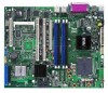
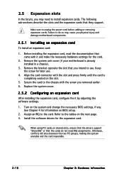
... card To install an expansion card: 1. Keep the screw for the card. 2. See Chapter 4 for the expansion card. Install the software drivers for information on shared slots, ensure that the drivers support "Share IRQ" or that came with the screw you intend to the chassis with it by adjusting the software settings...
... card To install an expansion card: 1. Keep the screw for the card. 2. See Chapter 4 for the expansion card. Install the software drivers for information on shared slots, ensure that the drivers support "Share IRQ" or that came with the screw you intend to the chassis with it by adjusting the software settings...
User Manual
Page 37
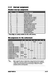
shared - - -- - - - - shared - - - - - - ASUS P5MT-M 2-17 shared - shared - - -- - - - When using PCI cards on shared slots, ensure that the drivers support "Share IRQ" or that the cards do not need IRQ assignments; shared shared -- - shared - - used - shared - - - shared - - - - - - -- - - otherwise, conflicts will arise between the two ...
shared - - -- - - - - shared - - - - - - ASUS P5MT-M 2-17 shared - shared - - -- - - - When using PCI cards on shared slots, ensure that the drivers support "Share IRQ" or that the cards do not need IRQ assignments; shared shared -- - shared - - used - shared - - - shared - - - - - - -- - - otherwise, conflicts will arise between the two ...

User Manual
Page 80
... options: [1.1] [1.4] 4-20 Chapter 4: BIOS setup Setting to Auto allows the system to configure the Multi-Processor table. The ownership should be claimed by the EHCI driver. MPS Configuration MPS Revision [1.4] Select MPS Revision. Configuration options: [Disabled] [2 USB Ports] [4 USB Ports] [6 USB Ports] [8 USB Ports] Legacy USB Support [Enabled] Allows you to...
... options: [1.1] [1.4] 4-20 Chapter 4: BIOS setup Setting to Auto allows the system to configure the Multi-Processor table. The ownership should be claimed by the EHCI driver. MPS Configuration MPS Revision [1.4] Select MPS Revision. Configuration options: [Disabled] [2 USB Ports] [4 USB Ports] [6 USB Ports] [8 USB Ports] Legacy USB Support [Enabled] Allows you to...
User Manual
Page 99
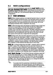
... disks perform the same work as mirroring alone. This RAID configuration provides data protection and increases fault tolerance to create a virtual RAID 0 and RAID 1 sets. ASUS P5MT-M 5-1 A minimum of four hard disk drives is a striped configuration with the I n t e l® I C H 7 R and the L S I L o g i c E m b e d d e d S .... 5.1 RAID configurations The server system/motherboard comes with RAID 1 segments whose segments are RAID 1 arrays. RAID driver installation" for fault-tolerance as a single drive but at a sustained data transfer rate, double that allows you ...
... disks perform the same work as mirroring alone. This RAID configuration provides data protection and increases fault tolerance to create a virtual RAID 0 and RAID 1 sets. ASUS P5MT-M 5-1 A minimum of four hard disk drives is a striped configuration with the I n t e l® I C H 7 R and the L S I L o g i c E m b e d d e d S .... 5.1 RAID configurations The server system/motherboard comes with RAID 1 segments whose segments are RAID 1 arrays. RAID driver installation" for fault-tolerance as a single drive but at a sustained data transfer rate, double that allows you ...
User Manual
Page 112
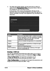
... the size and stripe size (RAID 1 only). In N e w C o n f i g u r a t i o n, you to create RAID 0, RAID 1, or RAID 10 set size and stripe size (RAID 1 only). 5-14 Chapter 5: Driver installation At the bottom of configurations: E a s y and N e w. This menu also allows you to view, add, or clear RAID configurations or select the boot drive Allows...
... the size and stripe size (RAID 1 only). In N e w C o n f i g u r a t i o n, you to create RAID 0, RAID 1, or RAID 10 set size and stripe size (RAID 1 only). 5-14 Chapter 5: Driver installation At the bottom of configurations: E a s y and N e w. This menu also allows you to view, add, or clear RAID configurations or select the boot drive Allows...

User Manual
Page 114
The configurable array appears on screen. 5. Select all the drives required for the RAID set, then press . The logical drive information appears including a Logical Drive menu that allows you to change the logical drive parameters. 5-16 Chapter 5: Driver installation 4. Press , select the configurable array, then press .
The configurable array appears on screen. 5. Select all the drives required for the RAID set, then press . The logical drive information appears including a Logical Drive menu that allows you to change the logical drive parameters. 5-16 Chapter 5: Driver installation 4. Press , select the configurable array, then press .
User Manual
Page 116
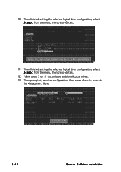
Follow steps 5 to 10 to the Management Menu. 5-18 Chapter 5: Driver installation 10. When prompted, save the configuration, then press to return to configure additional logical drives. 13. When finished setting the selected logical drive configuration, select A c c e p t from the menu, then press . 12. When finished setting the selected logical drive configuration, select A c c e p t from the menu, then press . 11.
Follow steps 5 to 10 to the Management Menu. 5-18 Chapter 5: Driver installation 10. When prompted, save the configuration, then press to return to configure additional logical drives. 13. When finished setting the selected logical drive configuration, select A c c e p t from the menu, then press . 12. When finished setting the selected logical drive configuration, select A c c e p t from the menu, then press . 11.
User Manual
Page 118
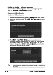
... the array number, and Y is the drive number. 5-20 The information of the selected hard disk drive displays at the bottom of the screen. Chapter 5: Driver installation When selected, the drive indicator changes from R E A D Y to the SATA ports. From the Management Menu, highlight C o n f i g u r e, then press . 2. Use the arrow keys to include...
... the array number, and Y is the drive number. 5-20 The information of the selected hard disk drive displays at the bottom of the screen. Chapter 5: Driver installation When selected, the drive indicator changes from R E A D Y to the SATA ports. From the Management Menu, highlight C o n f i g u r e, then press . 2. Use the arrow keys to include...
User Manual
Page 120
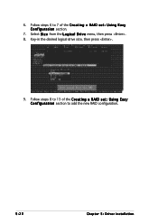
Key-in the desired logical drive size, then press . 9. Follow steps 6 to add the new RAID configuration. 5-22 Chapter 5: Driver installation Follow steps 8 to 13 of the C r e a t i n g a R A I D s e t : U s i n g E a s y C o n f i g u r a t i o n section to 7 of the C r e a t i n g a R A I D s e t : U s i n g E a s y C o n f i g u r a t i o n section. 7. Select S i z e from the L o g i c a l D r i v e menu, then press . 8. 6.
Key-in the desired logical drive size, then press . 9. Follow steps 6 to add the new RAID configuration. 5-22 Chapter 5: Driver installation Follow steps 8 to 13 of the C r e a t i n g a R A I D s e t : U s i n g E a s y C o n f i g u r a t i o n section to 7 of the C r e a t i n g a R A I D s e t : U s i n g E a s y C o n f i g u r a t i o n section. 7. Select S i z e from the L o g i c a l D r i v e menu, then press . 8. 6.

User Manual
Page 122
You may also press to select Y e s from the I n i t i a l i z e ? A progress bar appears on the drive. 4. Initializing a logical drive(s) erases all data on screen. dialog box, then press . 3. When prompted, press the to initialize the drive without confirmation. If desired, press to abort initialization. 5-24 Chapter 5: Driver installation
You may also press to select Y e s from the I n i t i a l i z e ? A progress bar appears on the drive. 4. Initializing a logical drive(s) erases all data on screen. dialog box, then press . 3. When prompted, press the to initialize the drive without confirmation. If desired, press to abort initialization. 5-24 Chapter 5: Driver installation
User Manual
Page 124
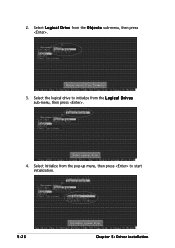
Select L o g i c a l D r i v e from the pop-up menu, then press to initialize from the L o g i c a l D r i v e s sub-menu, then press . 4. Select Initialize from the O b j e c t s sub-menu, then press . 3. Select the logical drive to start initialization. 5-26 Chapter 5: Driver installation 2.
Select L o g i c a l D r i v e from the pop-up menu, then press to initialize from the L o g i c a l D r i v e s sub-menu, then press . 4. Select Initialize from the O b j e c t s sub-menu, then press . 3. Select the logical drive to start initialization. 5-26 Chapter 5: Driver installation 2.
User Manual
Page 126
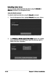
The P H Y S I C A L D R I V E S S E L E C T I O N M E N U displays the available drives connected to rebuild, then press . 5-28 Chapter 5: Driver installation Using the Rebuild command To rebuild a failed hard disk drive using the R e b u i l d or O b j e c t s command in the Management Menu. From the Management Menu, highlight R e b u i l d, then press . 2. Select the drive you want to the SATA ports. Rebuilding failed drives You can manually rebuild failed hard disk drives using the R e b u i l d command: 1.
The P H Y S I C A L D R I V E S S E L E C T I O N M E N U displays the available drives connected to rebuild, then press . 5-28 Chapter 5: Driver installation Using the Rebuild command To rebuild a failed hard disk drive using the R e b u i l d or O b j e c t s command in the Management Menu. From the Management Menu, highlight R e b u i l d, then press . 2. Select the drive you want to the SATA ports. Rebuilding failed drives You can manually rebuild failed hard disk drives using the R e b u i l d command: 1.

User Manual
Page 128
... data redundancy in a RAID 1 set (s) and prompts you to select the logical drive to select the logical drive from the L o g i c a l D r i v e selection, then press . 5-30 Chapter 5: Driver installation The screen displays the available RAID set .
... data redundancy in a RAID 1 set (s) and prompts you to select the logical drive to select the logical drive from the L o g i c a l D r i v e selection, then press . 5-30 Chapter 5: Driver installation The screen displays the available RAID set .

User Manual
Page 130
Using the Objects command To check data consistency using the O b j e c t s command: 1. When checking is complete, press any key to check the drive. 5. When prompted, press to to continue. 5-32 Chapter 5: Driver installation Select Check Consistency from the menu. 2. From the Management Menu, select O b j e c t s, then select L o g i c a l D r i v e from the pop-up menu, then press . 4. Use the arrow keys to select the logical drive you want to check, then press . 3.
Using the Objects command To check data consistency using the O b j e c t s command: 1. When checking is complete, press any key to check the drive. 5. When prompted, press to to continue. 5-32 Chapter 5: Driver installation Select Check Consistency from the menu. 2. From the Management Menu, select O b j e c t s, then select L o g i c a l D r i v e from the pop-up menu, then press . 4. Use the arrow keys to select the logical drive you want to check, then press . 3.

User Manual
Page 132
... logical drive is selected as boot drive. When prompted, press the to select the bootable logical drive from a RAID set. Refer to continue. 5-34 Chapter 5: Driver installation Selecting the boot drive from a RAID set You must have created a new RAID configuration before you can select the boot drive from the list...
... logical drive is selected as boot drive. When prompted, press the to select the bootable logical drive from a RAID set. Refer to continue. 5-34 Chapter 5: Driver installation Selecting the boot drive from a RAID set You must have created a new RAID configuration before you can select the boot drive from the list...

User Manual
Page 133
This chapter provides information on RAID, LAN and VGA driver installation for this motherboard. 6 Driver installation
This chapter provides information on RAID, LAN and VGA driver installation for this motherboard. 6 Driver installation
User Manual
Page 134
Chapter summary 6 6.1 RAID driver installation 6-1 6.2 LAN driver installation 6-7 6.3 VGA driver installation 6-11 ASUS P5MT-M
Chapter summary 6 6.1 RAID driver installation 6-1 6.2 LAN driver installation 6-7 6.3 VGA driver installation 6-11 ASUS P5MT-M


