User Manual
Page 15
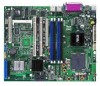
... cable 4 x Serial ATA signal cables 2 x Serial ATA power cable 1 x USB PCI cable bracket I/O shield ASUS motherboard support CD User guide If any of ASUS quality motherboards! The motherboard delivers a host of new features and latest technologies, making it , check the items in ...your package with the list below. 1.2 Package contents Check your motherboard package for buying an ASUS® P5MT-M motherboard! Before you for the following items. Motherboard ASUS P5MT-M motherboard Cables Accessories Application CD Documentation 2-in the long line of the above items is damaged or...
... cable 4 x Serial ATA signal cables 2 x Serial ATA power cable 1 x USB PCI cable bracket I/O shield ASUS motherboard support CD User guide If any of ASUS quality motherboards! The motherboard delivers a host of new features and latest technologies, making it , check the items in ...your package with the list below. 1.2 Package contents Check your motherboard package for buying an ASUS® P5MT-M motherboard! Before you for the following items. Motherboard ASUS P5MT-M motherboard Cables Accessories Application CD Documentation 2-in the long line of the above items is damaged or...
User Manual
Page 17
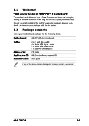
... software compatible with existing PCI specifications. See page 2-18 for details. See page 2-27 for details. See pages 2-20 and 2-29 for your networking needs. ASUS P5MT-M 1-3 Dual Gigabit LAN solution The motherboard comes with USB 1.1. The onboard Broadcom BCM5721 controllers use the PCI Express interface with RAID functionality. PCI Express™...
... software compatible with existing PCI specifications. See page 2-18 for details. See page 2-27 for details. See pages 2-20 and 2-29 for your networking needs. ASUS P5MT-M 1-3 Dual Gigabit LAN solution The motherboard comes with USB 1.1. The onboard Broadcom BCM5721 controllers use the PCI Express interface with RAID functionality. PCI Express™...
User Manual
Page 20
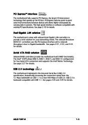
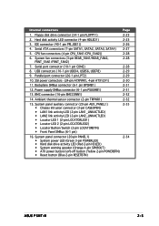
Chapter summary 2 2.1 Before you proceed 2-1 2.2 Motherboard overview 2-2 2.3 Central Processing Unit (CPU 2-6 2.4 System memory 2-13 2.5 Expansion slots 2-16 2.6 Jumpers 2-19 2.7 Connectors 2-24 ASUS P5MT-M
Chapter summary 2 2.1 Before you proceed 2-1 2.2 Motherboard overview 2-2 2.3 Central Processing Unit (CPU 2-6 2.4 System memory 2-13 2.5 Expansion slots 2-16 2.6 Jumpers 2-19 2.7 Connectors 2-24 ASUS P5MT-M
User Manual
Page 21
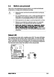
... due to static electricity. • Hold components by the edges to avoid touching the ICs on them. • Whenever you uninstall any motherboard component. P5MT-M ® LAN2 P5MT-M Onboard LED SB_PWR1 ON Standby Power OFF Powered Off ASUS P5MT-M 2-1 Failure to do so may cause severe damage to the motherboard, peripherals, and/or components.
... due to static electricity. • Hold components by the edges to avoid touching the ICs on them. • Whenever you uninstall any motherboard component. P5MT-M ® LAN2 P5MT-M Onboard LED SB_PWR1 ON Standby Power OFF Powered Off ASUS P5MT-M 2-1 Failure to do so may cause severe damage to the motherboard, peripherals, and/or components.
User Manual
Page 25
... HDLED) • System warning speaker (Orange 4-pin SPKROUT) • ATX power button/soft-off button (Yellow 2-pin POWERBTN) • Reset button (Blue 2-pin RESETBTN) 2-34 ASUS P5MT-M 2-5 Serial port connector (10-1 pin COM2) 2-28 8. SSI power connectors (24-pin ATXPWR1, 4-pin ATX12V1) 2-30 11. Power supply SMBus connector (6-1 pin PSUSMB1) 2-31 13...
... HDLED) • System warning speaker (Orange 4-pin SPKROUT) • ATX power button/soft-off button (Yellow 2-pin POWERBTN) • Reset button (Blue 2-pin RESETBTN) 2-34 ASUS P5MT-M 2-5 Serial port connector (10-1 pin COM2) 2-28 8. SSI power connectors (24-pin ATXPWR1, 4-pin ATX12V1) 2-30 11. Power supply SMBus connector (6-1 pin PSUSMB1) 2-31 13...
User Manual
Page 27
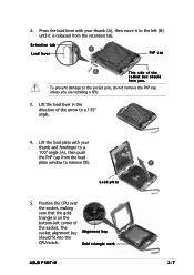
... socket. Lift the load plate with your thumb and forefinger to the socket pins, do not remove the PnP cap unless you . Gold triangle mark ASUS P5MT-M A 2-7 Retention tab A Load lever PnP cap B This side of the socket box should fit into the CPU notch. To prevent damage to a B 100º angle...
... socket. Lift the load plate with your thumb and forefinger to the socket pins, do not remove the PnP cap unless you . Gold triangle mark ASUS P5MT-M A 2-7 Retention tab A Load lever PnP cap B This side of the socket box should fit into the CPU notch. To prevent damage to a B 100º angle...

User Manual
Page 29
... motherboard. Make sure that the four fasteners match the holes on top of the groove pointing outward. (The photo shows the groove shaded for emphasis.) ASUS P5MT-M 2-9 Narrow end of the groove Motherboard hole Fastener Make sure to orient each fastener with the narrow end of the installed CPU, making sure that...
... motherboard. Make sure that the four fasteners match the holes on top of the groove pointing outward. (The photo shows the groove shaded for emphasis.) ASUS P5MT-M 2-9 Narrow end of the groove Motherboard hole Fastener Make sure to orient each fastener with the narrow end of the installed CPU, making sure that...

User Manual
Page 31
Rotate each fastener counterclockwise. 3. Pull up two fasteners at a time in a diagonal sequence to disengage the heatsink B and fan assembly from the connector on the motherboard. 2. A B A B B A ASUS P5MT-M 2-11 Disconnect the CPU fan cable from the A motherboard. 2.3.3 Uninstalling the CPU heatsink and fan To uninstall the CPU heatsink and fan: 1.
Rotate each fastener counterclockwise. 3. Pull up two fasteners at a time in a diagonal sequence to disengage the heatsink B and fan assembly from the connector on the motherboard. 2. A B A B B A ASUS P5MT-M 2-11 Disconnect the CPU fan cable from the A motherboard. 2.3.3 Uninstalling the CPU heatsink and fan To uninstall the CPU heatsink and fan: 1.
User Manual
Page 33
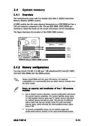
...system typically shows about 3~4 GB available memory space due to match the break on capacity and installation of the DDR2 DIMM sockets: P5MT-M ® LAN2 128 Pins P5MT-M 240-pin DDR2 DIMM sockets 112 Pins DIMM_A1 DIMM_A2 DIMM_B1 DIMM_B2 2.4.2 Memory configurations You may install 256 MB, 512 MB and... cards need larger memory space, which will vary for onboard devices and add-on cards that you obtain memory modules from the same vendor. ASUS P5MT-M 2-13 The figure illustrates the location of four 1 GB memory modules • Due to the 184-pin DDR DIMM. A DDR2 module...
...system typically shows about 3~4 GB available memory space due to match the break on capacity and installation of the DDR2 DIMM sockets: P5MT-M ® LAN2 128 Pins P5MT-M 240-pin DDR2 DIMM sockets 112 Pins DIMM_A1 DIMM_A2 DIMM_B1 DIMM_B2 2.4.2 Memory configurations You may install 256 MB, 512 MB and... cards need larger memory space, which will vary for onboard devices and add-on cards that you obtain memory modules from the same vendor. ASUS P5MT-M 2-13 The figure illustrates the location of four 1 GB memory modules • Due to the 184-pin DDR DIMM. A DDR2 module...
User Manual
Page 35
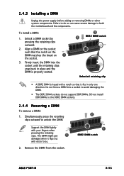
... keyed with a notch so that the notch on the DIMM matches the break on 1 the socket. 3. Remove the DIMM from the socket. 2 1 DDR2 DIMM notch ASUS P5MT-M 2-15 Failure to do not support DDR DIMMs. DO not install DDR DIMMs to the DDR2 DIMM sockets. 2.4.4 Removing a DIMM To remove a DIMM: 1. Simultaneously press...
... keyed with a notch so that the notch on the DIMM matches the break on 1 the socket. 3. Remove the DIMM from the socket. 2 1 DDR2 DIMM notch ASUS P5MT-M 2-15 Failure to do not support DDR DIMMs. DO not install DDR DIMMs to the DDR2 DIMM sockets. 2.4.4 Removing a DIMM To remove a DIMM: 1. Simultaneously press...
User Manual
Page 37
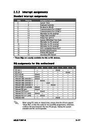
shared - - shared - - -- - - - shared - - -- - - - - shared - - - shared -- - - - - - - IRQ assignments for ISA or PCI devices. shared - - -- - - - - ASUS P5MT-M 2-17 shared - used - 2.5.3 Interrupt assignments Standard interrupt assignments IRQ Priority 0 1 1 2 2 - 3 11 4 12 5 13 6 14 7 15 8 3 9 4 10 5 11 6 12 7 13 8 14 9 15 10 Standard Function System ...
shared - - shared - - -- - - - shared - - -- - - - - shared - - - shared -- - - - - - - IRQ assignments for ISA or PCI devices. shared - - -- - - - - ASUS P5MT-M 2-17 shared - used - 2.5.3 Interrupt assignments Standard interrupt assignments IRQ Priority 0 1 1 2 2 - 3 11 4 12 5 13 6 14 7 15 8 3 9 4 10 5 11 6 12 7 13 8 14 9 15 10 Standard Function System ...
User Manual
Page 39
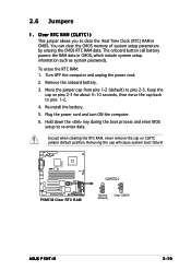
... cap on CLRTC jumper default position. Clear RTC RAM (CLRTC1) This jumper allows you to pins 2-3. Remove the onboard battery. 3. P5MT-M ® LAN2 P5MT-M Clear RTC RAM CLRTC1 2 1 Normal (Default) 3 2 Clear CMOS ASUS P5MT-M 2-19 The onboard button cell battery powers the RAM data in CMOS. Hold down the key during the boot process...
... cap on CLRTC jumper default position. Clear RTC RAM (CLRTC1) This jumper allows you to pins 2-3. Remove the onboard battery. 3. P5MT-M ® LAN2 P5MT-M Clear RTC RAM CLRTC1 2 1 Normal (Default) 3 2 Clear CMOS ASUS P5MT-M 2-19 The onboard button cell battery powers the RAM data in CMOS. Hold down the key during the boot process...
User Manual
Page 41
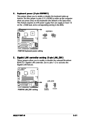
... setting LAN_EN1 2 1 Enable (Default) 3 2 Disable ASUS P5MT-M 2-21 This feature requires an ATX power supply that can supply at least 1A on the keyboard (the default is the Space Bar). Gigabit LAN ... wake up feature. Keyboard power (3-pin KBPWR1) This jumper allows you press a key on the +5VSB lead, and a corresponding setting in the BIOS. ® LAN2 P5MT-M KBPWR1 21 32 +5V (Default) +5VSB...
... setting LAN_EN1 2 1 Enable (Default) 3 2 Disable ASUS P5MT-M 2-21 This feature requires an ATX power supply that can supply at least 1A on the keyboard (the default is the Space Bar). Gigabit LAN ... wake up feature. Keyboard power (3-pin KBPWR1) This jumper allows you press a key on the +5VSB lead, and a corresponding setting in the BIOS. ® LAN2 P5MT-M KBPWR1 21 32 +5V (Default) +5VSB...
User Manual
Page 43
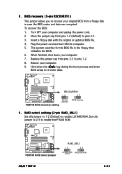
... ROM. Reboot your computer and unplug the power cord. 2. Insert a floppy disk with the original or updated BIOS file. 4. P5MT-M ® LAN2 RECOVERY1 12 23 Normal (Default) P5MT-M BIOS recovery setting BIOS recovery 9 . To recover the BIOS: 1. BIOS recovery (3-pin RECOVERY1) This jumper allows you to re...the computer. 5. When finished, shut down the < D e l > key during the boot process and enter BIOS setup to recover your computer. 7. 8. P5MT-M ® LAN2 P5MT-M RAID select jumper RAID_SEL1 12 23 LSI RAID ROM INTEL RAID ROM (Default) ASUS P5MT-M 2-23
... ROM. Reboot your computer and unplug the power cord. 2. Insert a floppy disk with the original or updated BIOS file. 4. P5MT-M ® LAN2 RECOVERY1 12 23 Normal (Default) P5MT-M BIOS recovery setting BIOS recovery 9 . To recover the BIOS: 1. BIOS recovery (3-pin RECOVERY1) This jumper allows you to re...the computer. 5. When finished, shut down the < D e l > key during the boot process and enter BIOS setup to recover your computer. 7. 8. P5MT-M ® LAN2 P5MT-M RAID select jumper RAID_SEL1 12 23 LSI RAID ROM INTEL RAID ROM (Default) ASUS P5MT-M 2-23

User Manual
Page 45
...pin FLOPPY1) This connector is for add-on the connector is removed to light up. ® LAN2 HDLED1 1 P5MT-M NC ADD_IN_CARD_ACT# ADD_IN_CARD_ACT# NC P5MT-M Hard disk activity LED connector ASUS P5MT-M 2-25 Insert one end of the cable to this connector, then connect the other end to the signal connector at...to the hard disk activity LED for the provided floppy disk drive (FDD) signal cable. The read/write activities of the floppy disk drive. P5MT-M ® LAN2 FLOPPY1 PIN 1 NOTE: Orient the red markings on cards cause the hard disk activity LED to prevent incorrect cable connection ...
...pin FLOPPY1) This connector is for add-on the connector is removed to light up. ® LAN2 HDLED1 1 P5MT-M NC ADD_IN_CARD_ACT# ADD_IN_CARD_ACT# NC P5MT-M Hard disk activity LED connector ASUS P5MT-M 2-25 Insert one end of the cable to this connector, then connect the other end to the signal connector at...to the hard disk activity LED for the provided floppy disk drive (FDD) signal cable. The read/write activities of the floppy disk drive. P5MT-M ® LAN2 FLOPPY1 PIN 1 NOTE: Orient the red markings on cards cause the hard disk activity LED to prevent incorrect cable connection ...

User Manual
Page 47
... Configuration" for Serial ATA hard disk drives. SATA1 GND RSATA_TXP1 RSATA_TXN1 GND RSATA_RXP1 RSATA_RXN1 GND P5MT-M GND RSATA_TXP2 RSATA_TXN2 GND RSATA_RXP2 RSATA_RXN2 GND ® LAN2 SATA2 SATA3 GND RSATA_TXP3 RSATA_TXN3 GND RSATA_RXP3 RSATA_RXN3 GND P5MT-M SATA connectors SATA4 GND RSATA_TXP4 RSATA_TXN4 GND RSATA_RXP4 RSATA_RXN4 GND When using these connectors. Serial..., set to [RAID]. Serial ATA hard disk drive connection Connector SATA1, SATA2 SATA3, SATA4 Setting Master Slave Use Boot disk Data disk ASUS P5MT-M 2-27 In S t a n d a r d I D E mode by default.
... Configuration" for Serial ATA hard disk drives. SATA1 GND RSATA_TXP1 RSATA_TXN1 GND RSATA_RXP1 RSATA_RXN1 GND P5MT-M GND RSATA_TXP2 RSATA_TXN2 GND RSATA_RXP2 RSATA_RXN2 GND ® LAN2 SATA2 SATA3 GND RSATA_TXP3 RSATA_TXN3 GND RSATA_RXP3 RSATA_RXN3 GND P5MT-M SATA connectors SATA4 GND RSATA_TXP4 RSATA_TXN4 GND RSATA_RXP4 RSATA_RXN4 GND When using these connectors. Serial..., set to [RAID]. Serial ATA hard disk drive connection Connector SATA1, SATA2 SATA3, SATA4 Setting Master Slave Use Boot disk Data disk ASUS P5MT-M 2-27 In S t a n d a r d I D E mode by default.

User Manual
Page 49
The USB connector complies with USB 2.0 specification that connects a parallel printer, a scanner, or other devices. P5MT-M ® LAN2 P5MT-M USB 2.0 connectors USB78 NC GND USB _P7+ USB_P7USB+5V USB56 NC GND USB _P5+ USB_P5USB+5V USB34 NC GND USB _P3+ USB_P3USB+5V GND USB_P8+ ... GND GND GND GND GND GND GND SLIN# PINIT# ERROR# AFD# SLCT PE BUSY ACK# SPD7 SPD6 SPD5 SPD4 SPD3 SPD2 SPD1 SPD0 STB# Pin 1 ASUS P5MT-M 2-29 Connect the USB module cable to this connector, then install the module to a slot opening at the back of the system chassis. Parallel port...
The USB connector complies with USB 2.0 specification that connects a parallel printer, a scanner, or other devices. P5MT-M ® LAN2 P5MT-M USB 2.0 connectors USB78 NC GND USB _P7+ USB_P7USB+5V USB56 NC GND USB _P5+ USB_P5USB+5V USB34 NC GND USB _P3+ USB_P3USB+5V GND USB_P8+ ... GND GND GND GND GND GND GND SLIN# PINIT# ERROR# AFD# SLCT PE BUSY ACK# SPD7 SPD6 SPD5 SPD4 SPD3 SPD2 SPD1 SPD0 STB# Pin 1 ASUS P5MT-M 2-29 Connect the USB module cable to this connector, then install the module to a slot opening at the back of the system chassis. Parallel port...

User Manual
Page 51
Devices communicate with an SMBus host and/or other SMBus devices using the SMBus interface. P5MT-M PSU_I2CCLK PSU_I2CDATA NC GND +3.3V Remote Sense ® LAN2 PSUSMB1 P5MT-M Power supply SMBus connector ASUS P5MT-M 2-31 Power supply SMBus connector (6-1 pin PSUSMB1) This connector allows you to connect SMBus (System Management Bus) devices. Backplane SMBus connector (6-1 pin...
Devices communicate with an SMBus host and/or other SMBus devices using the SMBus interface. P5MT-M PSU_I2CCLK PSU_I2CDATA NC GND +3.3V Remote Sense ® LAN2 PSUSMB1 P5MT-M Power supply SMBus connector ASUS P5MT-M 2-31 Power supply SMBus connector (6-1 pin PSUSMB1) This connector allows you to connect SMBus (System Management Bus) devices. Backplane SMBus connector (6-1 pin...
User Manual
Page 53
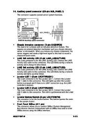
...controller is broken). • Locator LED 2 (2-pin LOCATORLED2) This 2-pin connector is for the Locator LED 1. ASUS P5MT-M 2-33 Devices communicate with the LAN2 LED. • Locator Button/Switch (2-pin LOCATORBTN) This connector is for the...cable to this connector. NC I2C_4_CLK# GND I2C_4_DATA# +5VSB LAN1_LINKACTLED+ LAN1_LINKACTLEDLAN2_LINKACTLEDLAN2_LINKACTLED+ P5MT-M ® LAN2 AUX_PANEL1 PIN1 +5VSB CASEOPEN GND LOCATORLED1+ LOCATORLED1LOCATORBTN# GND LOCATORLED2LOCATORLED2+ P5MT-M Auxiliary panel connector • Chassis Intrusion connector (3-pin CASEOPEN) This lead is...
...controller is broken). • Locator LED 2 (2-pin LOCATORLED2) This 2-pin connector is for the Locator LED 1. ASUS P5MT-M 2-33 Devices communicate with the LAN2 LED. • Locator Button/Switch (2-pin LOCATORBTN) This connector is for the...cable to this connector. NC I2C_4_CLK# GND I2C_4_DATA# +5VSB LAN1_LINKACTLED+ LAN1_LINKACTLEDLAN2_LINKACTLEDLAN2_LINKACTLED+ P5MT-M ® LAN2 AUX_PANEL1 PIN1 +5VSB CASEOPEN GND LOCATORLED1+ LOCATORLED1LOCATORBTN# GND LOCATORLED2LOCATORLED2+ P5MT-M Auxiliary panel connector • Chassis Intrusion connector (3-pin CASEOPEN) This lead is...

User Manual
Page 56
Chapter summary 3 3.1 Starting up for the first time 3-1 3.2 TUrning off the computer 3-2 ASUS P5MT-M
Chapter summary 3 3.1 Starting up for the first time 3-1 3.2 TUrning off the computer 3-2 ASUS P5MT-M


