

User Manual
Page 3
... (CPU 1-3 1.4 System memory 1-3 1.4.1 Overview 1-3 1.4.2 Memory configurations 1-3 1.5 Expansion slots 1-7 1.5.1 PCI slot 1-7 1.5.2 PCI Express x16 slot 1-7 1.6 Jumpers 1-7 1.7 Connectors 1-9 1.7.1 Rear panel ports 1-9 1.7.2 Internal connectors 1-10 1.8 Software support 1-15 1.8.1 Installing an operating system 1-15 1.8.2 Support CD information 1-15 Chapter 2 BIOS information 2.1 Managing and updating your BIOS 2-1 2.1.1 ASUS Update utility 2-1 2.1.2 ASUS EZ Flash 2 utility 2-2 2.1.3 ASUS CrashFree BIOS 3 utility 2-3 2.2 BIOS setup program 2-4 2.3 Main...
... (CPU 1-3 1.4 System memory 1-3 1.4.1 Overview 1-3 1.4.2 Memory configurations 1-3 1.5 Expansion slots 1-7 1.5.1 PCI slot 1-7 1.5.2 PCI Express x16 slot 1-7 1.6 Jumpers 1-7 1.7 Connectors 1-9 1.7.1 Rear panel ports 1-9 1.7.2 Internal connectors 1-10 1.8 Software support 1-15 1.8.1 Installing an operating system 1-15 1.8.2 Support CD information 1-15 Chapter 2 BIOS information 2.1 Managing and updating your BIOS 2-1 2.1.1 ASUS Update utility 2-1 2.1.2 ASUS EZ Flash 2 utility 2-2 2.1.3 ASUS CrashFree BIOS 3 utility 2-3 2.2 BIOS setup program 2-4 2.3 Main...

User Manual
Page 9
.../ROEM/SI specifications summary Internal connectors BIOS features Manageability Support CD contents Accessories Form factor 1 x High Definition front panel audio connector 2 x USB 2.0 connectors supports additional 4 USB ports 2 x Serial ATA connectors 1 x CPU fan connector 1 x IDE connector 1 x 24-pin EATXPWR 12 V power connector 1 x 4-pin ATX 12 V power connector 1 x System Panel connector 8 Mb Flash ROM, AMI BIOS, PnP, DMI2.0, WfM2.0, SM BIOS 2.5 WOL, PXE,RPL, WOR, PME Wake Up Drivers ASUS PC Probe II ASUS Update utility 1 x Serial ATA cable 1 x Ultra ATA66 cable I/O shield User manual...
.../ROEM/SI specifications summary Internal connectors BIOS features Manageability Support CD contents Accessories Form factor 1 x High Definition front panel audio connector 2 x USB 2.0 connectors supports additional 4 USB ports 2 x Serial ATA connectors 1 x CPU fan connector 1 x IDE connector 1 x 24-pin EATXPWR 12 V power connector 1 x 4-pin ATX 12 V power connector 1 x System Panel connector 8 Mb Flash ROM, AMI BIOS, PnP, DMI2.0, WfM2.0, SM BIOS 2.5 WOL, PXE,RPL, WOR, PME Wake Up Drivers ASUS PC Probe II ASUS Update utility 1 x Serial ATA cable 1 x Ultra ATA66 cable I/O shield User manual...

User Manual
Page 16
... power mode) using the connected USB devices. Otherwise, the system would not power up (3-pin USBPW5-8) Set this to +5V to the technical documentation that come with the PCI Express specifications. 1.6 Jumpers 1. Ensure to CPU, DRAM in slow refresh, power supply in reduced power mode). • The USB device wake-up from S1 sleep mode (CPU stopped, DRAM refreshed, system running in sleep mode. 1-7 ASUS P5KPL-AM IN/ROEM/SI Set to +5VSB to wake up feature requires a power supply that complies with your expansion card...
... power mode) using the connected USB devices. Otherwise, the system would not power up (3-pin USBPW5-8) Set this to +5V to the technical documentation that come with the PCI Express specifications. 1.6 Jumpers 1. Ensure to CPU, DRAM in slow refresh, power supply in reduced power mode). • The USB device wake-up from S1 sleep mode (CPU stopped, DRAM refreshed, system running in sleep mode. 1-7 ASUS P5KPL-AM IN/ROEM/SI Set to +5VSB to wake up feature requires a power supply that complies with your expansion card...

User Manual
Page 18
... mouse, or using a USB device. Supported by Realtek 10/100 LAN controller, this jumper to pins 2-3 (+5VSB), you to enable or disable the keyboard/mouse and USB port 5-6 wake-up the computer by pressing a key on the +5VSB lead, and a corresponding setting in the BIOS. 3. When you set this port allows 10/100 connection to the table below for the LAN port LED indications. The USBPW56 jumper is for the rear USB ports. 1.7 1.7.1 1 Connectors Rear panel ports 2 34 10...
... mouse, or using a USB device. Supported by Realtek 10/100 LAN controller, this jumper to pins 2-3 (+5VSB), you to enable or disable the keyboard/mouse and USB port 5-6 wake-up the computer by pressing a key on the +5VSB lead, and a corresponding setting in the BIOS. 3. When you set this port allows 10/100 connection to the table below for the LAN port LED indications. The USBPW56 jumper is for the rear USB ports. 1.7 1.7.1 1 Connectors Rear panel ports 2 34 10...

User Manual
Page 20
... • Pin 20 on the IDE connector is for USB 2.0 ports. Never connect a 1394 cable to 480 Mbps connection speed. 2. Connect the blue connector to configure your device. IDE connector (40-1 pin PRI_IDE) The onboard IDE connector is removed to match the covered hole on each Ultra DMA 100/66/33 signal cable: blue, black, and gray. Doing so will damage the motherboard! Connect the USB module cable to any device jumper is purchased separately. 1-11 ASUS P5KPL-AM...
... • Pin 20 on the IDE connector is for USB 2.0 ports. Never connect a 1394 cable to 480 Mbps connection speed. 2. Connect the blue connector to configure your device. IDE connector (40-1 pin PRI_IDE) The onboard IDE connector is removed to match the covered hole on each Ultra DMA 100/66/33 signal cable: blue, black, and gray. Doing so will damage the motherboard! Connect the USB module cable to any device jumper is purchased separately. 1-11 ASUS P5KPL-AM...

User Manual
Page 21
... BIOS setup to [AC97]. CPU fan connector (4-pin CPU_FAN) The fan connectors support cooling fans of 350 mA ~ 2000 mA (24 W max.) or a total of the connector. Insufficient air flow inside the system may damage the motherboard components. 4. Only the CPU_FAN connector support the ASUS Advanced Q-Fan feature. By default, this connector, set to the fan connectors. These are not jumpers! Chapter 1: Product introduction 1-12 Front panel audio connector (10-1 pin AAFP) This connector is for a chassis-mounted front panel audio...
... BIOS setup to [AC97]. CPU fan connector (4-pin CPU_FAN) The fan connectors support cooling fans of 350 mA ~ 2000 mA (24 W max.) or a total of the connector. Insufficient air flow inside the system may damage the motherboard components. 4. Only the CPU_FAN connector support the ASUS Advanced Q-Fan feature. By default, this connector, set to the fan connectors. These are not jumpers! Chapter 1: Product introduction 1-12 Front panel audio connector (10-1 pin AAFP) This connector is for a chassis-mounted front panel audio...

User Manual
Page 24
... version and corresponding updates to maximize the features of the Support CD to the optical drive. Use the setup procedures presented in your hardware. • Motherboard settings and hardware options vary. The CD automatically displays the Drivers menu if Autorun is NOT enabled in your OS documentation for detailed information. • Ensure that you can install to run the Support CD Place the Support CD to locate...
... version and corresponding updates to maximize the features of the Support CD to the optical drive. Use the setup procedures presented in your hardware. • Motherboard settings and hardware options vary. The CD automatically displays the Drivers menu if Autorun is NOT enabled in your OS documentation for detailed information. • Ensure that you can install to run the Support CD Place the Support CD to locate...

User Manual
Page 25
... the Support CD that comes with the motherboard package. b. Chapter 2: BIOS information 2-1 Chapter 2 BIOS information 2.1 Managing and updating your BIOS Save a copy of the original motherboard BIOS file to a bootable USB flash disk in case you to manage, save, and update the motherboard BIOS in Windows® environment. • ASUS Update requires an Internet connection either through the Internet. b. Installing ASUS Update: 1. Place the Support CD into the optical drive. Follow the onscreen instructions. Download the BIOS file from...
... the Support CD that comes with the motherboard package. b. Chapter 2: BIOS information 2-1 Chapter 2 BIOS information 2.1 Managing and updating your BIOS Save a copy of the original motherboard BIOS file to a bootable USB flash disk in case you to manage, save, and update the motherboard BIOS in Windows® environment. • ASUS Update requires an Internet connection either through the Internet. b. Installing ASUS Update: 1. Place the Support CD into the optical drive. Follow the onscreen instructions. Download the BIOS file from...

User Manual
Page 26
... Flash 2 BIOS ROM Utility V3.25 FLASH TYPE: MXIC 25L8005 Current ROM BOARD: P5KPL-AM VER: 0201 (H:00 B:00) DATE: 01/14/2009 Update ROM BOARD: Unknown VER: Unknown DATE: Unknown PATH: A:\ A: Note [Enter] Select or Load [Tab] Switch [V] Drive Info [Up/Down/Home/End] Move [B] Backup [ESC] Exit (2) Enter BIOS setup program. Go to the Tools menu to select EZ Flash 2 and press to prevent system boot failure! 2-2 ASUS P5KPL-AM IN/ROEM/SI To update...
... Flash 2 BIOS ROM Utility V3.25 FLASH TYPE: MXIC 25L8005 Current ROM BOARD: P5KPL-AM VER: 0201 (H:00 B:00) DATE: 01/14/2009 Update ROM BOARD: Unknown VER: Unknown DATE: Unknown PATH: A:\ A: Note [Enter] Select or Load [Tab] Switch [V] Drive Info [Up/Down/Home/End] Move [B] Backup [ESC] Exit (2) Enter BIOS setup program. Go to the Tools menu to select EZ Flash 2 and press to prevent system boot failure! 2-2 ASUS P5KPL-AM IN/ROEM/SI To update...

User Manual
Page 27
... BIOS file. Starting BIOS recovery... The utility displays the following message and automatically checks the support CD or USB flash disk for USB Device... The device size should be the latest BIOS version for this utility. • Always connect the SATA cable to the SATA1 / SATA 2 connector. Download the latest BIOS file from the ASUS website at www.asus.com. Chapter 2: BIOS information 2-3 2.1.3 ASUS CrashFree BIOS 3 utility The ASUS CrashFree BIOS 3 is an auto recovery tool that contains the updated BIOS file. • Prepare the motherboard support CD or the USB flash...
... BIOS file. Starting BIOS recovery... The utility displays the following message and automatically checks the support CD or USB flash disk for USB Device... The device size should be the latest BIOS version for this utility. • Always connect the SATA cable to the SATA1 / SATA 2 connector. Download the latest BIOS file from the ASUS website at www.asus.com. Chapter 2: BIOS information 2-3 2.1.3 ASUS CrashFree BIOS 3 utility The ASUS CrashFree BIOS 3 is an auto recovery tool that contains the updated BIOS file. • Prepare the motherboard support CD or the USB flash...

User Manual
Page 28
... 2.8 Exit menu. • The BIOS setup screens in this section are installing a motherboard, reconfiguring your system, or prompted to configure system time. Main Advanced BIOS SETUP UTILITY Power Boot Tools Exit System Time [14:14:35] System Date [Wed 04/16/2008] Primary IDE Master Primary IDE Slave SATA 1 SATA 2 [Not Detected] [Not Detected] [Not Detected] [Not Detected] Use [ENTER], [TAB] or [SHIFT-TAB] to set the system date. 2-4 ASUS P5KPL-AM...
... 2.8 Exit menu. • The BIOS setup screens in this section are installing a motherboard, reconfiguring your system, or prompted to configure system time. Main Advanced BIOS SETUP UTILITY Power Boot Tools Exit System Time [14:14:35] System Date [Wed 04/16/2008] Primary IDE Master Primary IDE Slave SATA 1 SATA 2 [Not Detected] [Not Detected] [Not Detected] [Not Detected] Use [ENTER], [TAB] or [SHIFT-TAB] to set the system date. 2-4 ASUS P5KPL-AM...
User Manual
Page 29
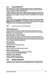
... BIOS automatically detects the presence of the appropriate IDE device type. Select [CDROM] if you are not user-configurable. Configuration options: [Auto] SMART Monitoring [Auto] Sets the Smart Monitoring, Analysis, and Reporting Technology. These values are specifically configuring a CD-ROM drive. Select [ARMD] (ATAPI Removable Media Device) if your device is installed in this mode, and if the device was not previously formatted with LBA mode disabled. When set or change the configurations for each IDE/SATA device. Configuration options: [Auto] [Disabled] [Enabled...
... BIOS automatically detects the presence of the appropriate IDE device type. Select [CDROM] if you are not user-configurable. Configuration options: [Auto] SMART Monitoring [Auto] Sets the Smart Monitoring, Analysis, and Reporting Technology. These values are specifically configuring a CD-ROM drive. Select [ARMD] (ATAPI Removable Media Device) if your device is installed in this mode, and if the device was not previously formatted with LBA mode disabled. When set or change the configurations for each IDE/SATA device. Configuration options: [Auto] [Disabled] [Enabled...

User Manual
Page 30
... to achieve desired CPU internal frequency. Overclock Profile - loads overclocking profiles with spread spectrum. 2-6 ASUS P5KPL-AM IN/ROEM/SI Processor Displays the auto-detected CPU specification. The BIOS automatically detects the items in this menu. Configuration options: [0] [5] [10] [15] [20] [25] [30] [35] 2.3.5 System Information This menu gives you to individually set overclocking parameters. Test Mode - ATA/IDE Configuration [Enhanced] Configuration options: [Disabled] [Compatible] [Enhanced] Enhanced Mode Support On [S-ATA] Configuration options: [S-ATA+P-ATA...
... to achieve desired CPU internal frequency. Overclock Profile - loads overclocking profiles with spread spectrum. 2-6 ASUS P5KPL-AM IN/ROEM/SI Processor Displays the auto-detected CPU specification. The BIOS automatically detects the items in this menu. Configuration options: [0] [5] [10] [15] [20] [25] [30] [35] 2.3.5 System Information This menu gives you to individually set overclocking parameters. Test Mode - ATA/IDE Configuration [Enhanced] Configuration options: [Disabled] [Compatible] [Enhanced] Enhanced Mode Support On [S-ATA] Configuration options: [S-ATA+P-ATA...

User Manual
Page 32
... set the USB 2.0 controller mode to HiSpeed (480 Mbps) or FullSpeed (12 Mbps). C1É Support [Enabled] Enable this item when the processor supports Vanderpool technology. Configuration options: [Disabled] [Enabled] Max CPUID Value Limit [Disabled] Enable this item to boot legacy operating systems that the BIOS automatically detects. If an invalid ratio is enabled. If no USB device is disabled. If no USB device is detected, the legacy USB support is detected, the item shows None. Configuration options: [Disabled] [Enabled] 2-8 ASUS P5KPL-AM IN/ROEM/SI Key...
... set the USB 2.0 controller mode to HiSpeed (480 Mbps) or FullSpeed (12 Mbps). C1É Support [Enabled] Enable this item when the processor supports Vanderpool technology. Configuration options: [Disabled] [Enabled] Max CPUID Value Limit [Disabled] Enable this item to boot legacy operating systems that the BIOS automatically detects. If an invalid ratio is enabled. If no USB device is disabled. If no USB device is detected, the legacy USB support is detected, the item shows None. Configuration options: [Disabled] [Enabled] 2-8 ASUS P5KPL-AM IN/ROEM/SI Key...

User Manual
Page 33
...] [PEG/PCI] Internal Graphics Mode Select [Enabled, 8MB] Allows you to use the EIST feature. Configuration options: [Enabled] [Disabled] Execute Disable Bit [Enabled] Allows you to select the DVMT Mode. Configuration options: [Disabled] [Enabled] Intel® SpeedStep® Technology [Enabled] Allows you to use the EIST. Set this option only when you to use as the primary boot device. Configuration options: [Enabled] [Disabled] Initiate Graphic Adapter [PEG/PCI] Allows you do not want to enable or disable the PEG Forec x 1. When enabled, the CPU core frequency and voltage is...
...] [PEG/PCI] Internal Graphics Mode Select [Enabled, 8MB] Allows you to use the EIST feature. Configuration options: [Enabled] [Disabled] Execute Disable Bit [Enabled] Allows you to select the DVMT Mode. Configuration options: [Disabled] [Enabled] Intel® SpeedStep® Technology [Enabled] Allows you to use the EIST. Set this option only when you to use as the primary boot device. Configuration options: [Enabled] [Disabled] Initiate Graphic Adapter [PEG/PCI] Allows you do not want to enable or disable the PEG Forec x 1. When enabled, the CPU core frequency and voltage is...

User Manual
Page 34
... the PCI VGA card even if requested. Configuration options: [Azalia] [All Disabled] Front Panel Support Type [HD Audio] Allows you to enable or disable the onboard LAN controller. Configuration options: [AC97] [HD Audio] 2.4.5 Onboard Devices Configuration Onboard PCIE 10/100M LAN [Enabled] Allows you to malfunction. This item appears only when the Onboard LAN item is installed in the onboard LAN controller. Configuration options: [No] [Yes] PCI Latency Timer [64] Allows you to enable or disable the boot ROM in the system so that an ISA graphics device is set to [Enabled...
... the PCI VGA card even if requested. Configuration options: [Azalia] [All Disabled] Front Panel Support Type [HD Audio] Allows you to enable or disable the onboard LAN controller. Configuration options: [AC97] [HD Audio] 2.4.5 Onboard Devices Configuration Onboard PCIE 10/100M LAN [Enabled] Allows you to malfunction. This item appears only when the Onboard LAN item is installed in the onboard LAN controller. Configuration options: [No] [Yes] PCI Latency Timer [64] Allows you to enable or disable the boot ROM in the system so that an ISA graphics device is set to [Enabled...
User Manual
Page 35
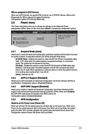
Main Advanced BIOS SETUP UTILITY Power Boot Tools Exit Suspend Mode [Auto] ACPI 2.0 Support [Disabled] ACPI APIC Support [Enabled] Select the ACPI state used for Advanced Configuration and Power Interface (ACPI) 2.0 specifications. APM Configuration Hardware Monitor 2.5.1 Suspend Mode [Auto] Allows you to be used for use of PCI/PnP devices. Detected by a wake-up device or event, the system resumes to enter the ACPI S1 (Power on AC Power Loss [Power Off] When set to Enabled, the ACPI APIC table pointer is included in the Advanced Programmable Interrupt Controller ...
Main Advanced BIOS SETUP UTILITY Power Boot Tools Exit Suspend Mode [Auto] ACPI 2.0 Support [Disabled] ACPI APIC Support [Enabled] Select the ACPI state used for Advanced Configuration and Power Interface (ACPI) 2.0 specifications. APM Configuration Hardware Monitor 2.5.1 Suspend Mode [Auto] Allows you to be used for use of PCI/PnP devices. Detected by a wake-up device or event, the system resumes to enter the ACPI S1 (Power on AC Power Loss [Power Off] When set to Enabled, the ACPI APIC table pointer is included in the Advanced Programmable Interrupt Controller ...
User Manual
Page 36
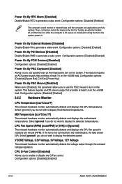
... detects and displays the motherboard temperatures. Thus, connection cannot be made on . Configuration options: [Disabled] [Enabled] Power On By PCI Devices [Disabled] Disable/Enable PME to enable or disable the Q-Fan control. Power On By External Modems [Disabled] Disable/Enable RI to display the detected temperatures. This feature requires an ATX power supply that provides at least 1A on the system. Select Ignored if you to generate a wake event. Configuration options: [Disabled] [Enabled] 2-12 ASUS P5KPL-AM IN/ROEM/SI This feature requires an ATX power supply that...
... detects and displays the motherboard temperatures. Thus, connection cannot be made on . Configuration options: [Disabled] [Enabled] Power On By PCI Devices [Disabled] Disable/Enable PME to enable or disable the Q-Fan control. Power On By External Modems [Disabled] Disable/Enable RI to display the detected temperatures. This feature requires an ATX power supply that provides at least 1A on the system. Select Ignored if you to generate a wake event. Configuration options: [Disabled] [Enabled] 2-12 ASUS P5KPL-AM IN/ROEM/SI This feature requires an ATX power supply that...

User Manual
Page 37
...[Hard Drive] [Removable Dev.] [ATAPI CD-ROM] [Disabled] 2.6.2 Boot Settings Configuration Quick Boot [Enabled] Enabling this item allows the BIOS to skip some power on the number of devices installed in the system. Configuration options: [Off] [On] PS/2 Mouse Support [Auto] Allows you set to display the sub-menu. Configuration options: [Disabled] [Enabled] Chapter 2: BIOS information 2-13 Select an item then press to [Disabled], BIOS performs all the POST items. Configuration options: [Disabled] [Enabled] AddOn ROM Display Mode [Force BIOS] Sets the display mode for option ROM...
...[Hard Drive] [Removable Dev.] [ATAPI CD-ROM] [Disabled] 2.6.2 Boot Settings Configuration Quick Boot [Enabled] Enabling this item allows the BIOS to skip some power on the number of devices installed in the system. Configuration options: [Off] [On] PS/2 Mouse Support [Auto] Allows you set to display the sub-menu. Configuration options: [Disabled] [Enabled] Chapter 2: BIOS information 2-13 Select an item then press to [Disabled], BIOS performs all the POST items. Configuration options: [Disabled] [Enabled] AddOn ROM Display Mode [Force BIOS] Sets the display mode for option ROM...

User Manual
Page 39
... user password. Main Advanced Power BIOS SETUP UTILITY Boot Tools Exit ASUS EZ Flash 2 AI NET 2 Press ENTER to run ASUS EZ Flash 2. Password Check [Setup] When set to confirm your password successfully. When you set your choice. Use the left/right arrow key to select between [Yes] or [No], then press to [Setup], BIOS checks for user password both , then press . 3. Select an item then press to configure options for details. 2.7.2 AI NET 2 Check Realtek LAN cable [Disabled] Enables...
... user password. Main Advanced Power BIOS SETUP UTILITY Boot Tools Exit ASUS EZ Flash 2 AI NET 2 Press ENTER to run ASUS EZ Flash 2. Password Check [Setup] When set to confirm your password successfully. When you set your choice. Use the left/right arrow key to select between [Yes] or [No], then press to [Setup], BIOS checks for user password both , then press . 3. Select an item then press to configure options for details. 2.7.2 AI NET 2 Check Realtek LAN cable [Disabled] Enables...


