User Manual
Page 7
These devices could interrupt the grounding circuit. • Make sure that your power supply is set to the correct voltage in municipal waste. vii If you are not sure about the voltage of the electrical outlet you are not ... wet. • Place the product on it, carefully read all the manuals that all cables are correctly connected and the power cables are using, contact your local power company. • If the power supply is organized This guide contains the following parts: • Chapter 1: Product introduction This chapter describes the features of the crossed...
These devices could interrupt the grounding circuit. • Make sure that your power supply is set to the correct voltage in municipal waste. vii If you are not sure about the voltage of the electrical outlet you are not ... wet. • Place the product on it, carefully read all the manuals that all cables are correctly connected and the power cables are using, contact your local power company. • If the power supply is organized This guide contains the following parts: • Chapter 1: Product introduction This chapter describes the features of the crossed...

User Manual
Page 14
...component. • Before handling components, use a grounded wrist strap or touch a safely grounded object or a metal object, such as the power supply case, to avoid damaging them due to static electricity. • Hold components by the edges to avoid touching the ICs on them. ... below shows the location of the following precautions before you install motherboard components or change any motherboard settings. • Unplug the power cord from the power supply. 1.4 Before you proceed Take note of the onboard LED. 1-4 Chapter 1: Product introduction Failure to do so may cause severe...
...component. • Before handling components, use a grounded wrist strap or touch a safely grounded object or a metal object, such as the power supply case, to avoid damaging them due to static electricity. • Hold components by the edges to avoid touching the ICs on them. ... below shows the location of the following precautions before you install motherboard components or change any motherboard settings. • Unplug the power cord from the power supply. 1.4 Before you proceed Take note of the onboard LED. 1-4 Chapter 1: Product introduction Failure to do so may cause severe...
User Manual
Page 27
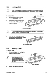
... Unplug the power supply before adding or removing DIMMs or other system components. Align a DIMM on the socket. 1 2 DDR2 DIMM notch 1 Unlocked retaining clip A DDR2 DIMM is properly seated. Locked Retaining Clip 1.7.4 Removing a DIMM To remove a DIMM: 1. Press the retaining clips outward to both the motherboard and the components. ASUS P5KPL-AM EPU 1-17 To...
... Unplug the power supply before adding or removing DIMMs or other system components. Align a DIMM on the socket. 1 2 DDR2 DIMM notch 1 Unlocked retaining clip A DDR2 DIMM is properly seated. Locked Retaining Clip 1.7.4 Removing a DIMM To remove a DIMM: 1. Press the retaining clips outward to both the motherboard and the components. ASUS P5KPL-AM EPU 1-17 To...
User Manual
Page 29
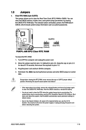
... steps above do not need to clear the RTC when the system hangs due to overclocking. function. ASUS P5KPL-AM EPU 1-19 Turn OFF the computer and unplug the power cord. 2. Plug the power cord and turn off is required before rebooting the system. Shut down the key during the boot process... system, then the BIOS automatically resets parameter settings to default values. • Due to the chipset limitation, AC power off and on the power supply or unplug and plug the power cord before you to re-enter data. Except when clearing the RTC RAM, never remove the cap on pins 2-3...
... steps above do not need to clear the RTC when the system hangs due to overclocking. function. ASUS P5KPL-AM EPU 1-19 Turn OFF the computer and unplug the power cord. 2. Plug the power cord and turn off is required before rebooting the system. Shut down the key during the boot process... system, then the BIOS automatically resets parameter settings to default values. • Due to the chipset limitation, AC power off and on the power supply or unplug and plug the power cord before you to re-enter data. Except when clearing the RTC RAM, never remove the cap on pins 2-3...

User Manual
Page 30
... a key on the +5VSB lead, and a corresponding setting in reduced power mode). 3. This feature requires an ATX power supply that can wake up (3-pin USBPW1-4, USBPW5-8) Set the jumpers to +5V to pins 2-3 (+5VSB), you can supply at least 1A on the keyboard (the default is the Space Bar)s.... When you to CPU, DRAM in slow refresh, power supply in the BIOS. 1-20 Chapter 1: Product introduction 2. Keyboard power (3-pin KBPWR) This jumper allows you set this jumper to...
... a key on the +5VSB lead, and a corresponding setting in reduced power mode). 3. This feature requires an ATX power supply that can wake up (3-pin USBPW1-4, USBPW5-8) Set the jumpers to +5V to pins 2-3 (+5VSB), you can supply at least 1A on the keyboard (the default is the Space Bar)s.... When you to CPU, DRAM in slow refresh, power supply in the BIOS. 1-20 Chapter 1: Product introduction 2. Keyboard power (3-pin KBPWR) This jumper allows you set this jumper to...
User Manual
Page 33
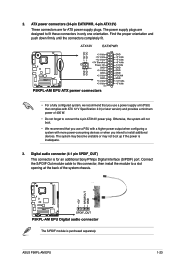
...module to a slot opening at the back of 400 W. • Do not forget to connect the 4-pin ATX12V power plug. ASUS P5KPL-AM EPU 1-23 ATX power connectors (24-pin EATXPWR, 4-pin ATX12V) These connectors are designed to install additional devices. The S/PDIF module is ...inadequate. 3. Otherwise, the system will not boot. • We recommend that complies with more power-consuming devices or when you use a power supply...
...module to a slot opening at the back of 400 W. • Do not forget to connect the 4-pin ATX12V power plug. ASUS P5KPL-AM EPU 1-23 ATX power connectors (24-pin EATXPWR, 4-pin ATX12V) These connectors are designed to install additional devices. The S/PDIF module is ...inadequate. 3. Otherwise, the system will not boot. • We recommend that complies with more power-consuming devices or when you use a power supply...
User Manual
Page 54
.... When this parameter allows you to use specific keys on the keyboard to generate a wake event. This feature requires an ATX power supply that provides at least 1A on the +5VSB lead. When set to Enabled, the items RTC Alarm Date, RTC Alarm Hour, RTC Alarm ...External Modems [Disabled] This allows either off mode. When set values. This feature requires an ATX power supply that provides at least 1A on the +5VSB lead. Configuration options: [Disabled] [Space Bar] [Ctrl-Esc] [Power Key] Power On By PS/2 Mouse [Disabled] When set to [Enabled], this item is set to [Enabled],...
.... When this parameter allows you to use specific keys on the keyboard to generate a wake event. This feature requires an ATX power supply that provides at least 1A on the +5VSB lead. When set to Enabled, the items RTC Alarm Date, RTC Alarm Hour, RTC Alarm ...External Modems [Disabled] This allows either off mode. When set values. This feature requires an ATX power supply that provides at least 1A on the +5VSB lead. Configuration options: [Disabled] [Space Bar] [Ctrl-Esc] [Power Key] Power On By PS/2 Mouse [Disabled] When set to [Enabled], this item is set to [Enabled],...


