P5GD2 user's manual
Page 15
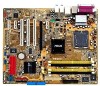
... technologies, making it , check the items in the long line of the above items is damaged or missing, contact your motherboard package for buying an ASUS® P5GD2 motherboard! Thank you start installing the motherboard, and hardware devices on it another standout in your package with the list below. 1.2 Package contents Check...
... technologies, making it , check the items in the long line of the above items is damaged or missing, contact your motherboard package for buying an ASUS® P5GD2 motherboard! Thank you start installing the motherboard, and hardware devices on it another standout in your package with the list below. 1.2 Package contents Check...

P5GD2 user's manual
Page 17
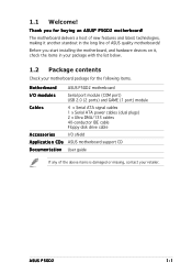
... CODEC comes with an AC-3 encoder capable of each jack, impedance sensing to determine audio device classes, and pre-defined equalization for various audio devices. ASUS P5GD2 1-3 The Intel® ICH6R allows RAID 0 and RAID 1 configuration for details. With the CODEC, 8-channel audio ports, and S/PDIF interfaces, you to select the best...
... CODEC comes with an AC-3 encoder capable of each jack, impedance sensing to determine audio device classes, and pre-defined equalization for various audio devices. ASUS P5GD2 1-3 The Intel® ICH6R allows RAID 0 and RAID 1 configuration for details. With the CODEC, 8-channel audio ports, and S/PDIF interfaces, you to select the best...
P5GD2 user's manual
Page 19
... silent operation. See page 4-20 for details. See pages 4-22 and 5-11 for details. ASUS P5GD2 1-5 See page 2-3 for details. AI NOS™ (Non-Delay Overclocking System) ASUS Non-delay Overclocking System™ (NOS) is a technology that detects and reports Ethernet cable faults...under the motherboard CPU socket, Stack Cool effectively lowers the system temperature by large capacitors and motherboard components. 1.3.2 ASUS Proactive features ASUS Stack Cool ASUS Stack Cool is a BIOS-based diagnostic tool that auto-detects the CPU loading and dynamically overclocks the CPU ...
... silent operation. See page 4-20 for details. See pages 4-22 and 5-11 for details. ASUS P5GD2 1-5 See page 2-3 for details. AI NOS™ (Non-Delay Overclocking System) ASUS Non-delay Overclocking System™ (NOS) is a technology that detects and reports Ethernet cable faults...under the motherboard CPU socket, Stack Cool effectively lowers the system temperature by large capacitors and motherboard components. 1.3.2 ASUS Proactive features ASUS Stack Cool ASUS Stack Cool is a BIOS-based diagnostic tool that auto-detects the CPU loading and dynamically overclocks the CPU ...
P5GD2 user's manual
Page 22
Chapter summary 2.1 Before you proceed 2-1 2.2 Motherboard overview 2-2 2.3 Central Processing Unit (CPU 2-7 2.4 System memory 2-13 2.5 Expansion slots 2-16 2.6 Jumpers 2-19 2.7 Connectors 2-22 ASUS P5GD2
Chapter summary 2.1 Before you proceed 2-1 2.2 Motherboard overview 2-2 2.3 Central Processing Unit (CPU 2-7 2.4 System memory 2-13 2.5 Expansion slots 2-16 2.6 Jumpers 2-19 2.7 Connectors 2-22 ASUS P5GD2
P5GD2 user's manual
Page 23
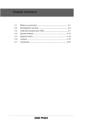
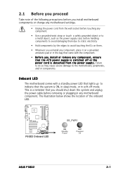
This is a reminder that the system is switched off mode. P5GD2 R P5GD2 Onboard LED SB_PWR1 ON Standby Power OFF Powered Off ASUS P5GD2 2-1 The illustration below shows the location of the following precautions before you install motherboard components or change any motherboard settings. • Unplug the power cord ...
This is a reminder that the system is switched off mode. P5GD2 R P5GD2 Onboard LED SB_PWR1 ON Standby Power OFF Powered Off ASUS P5GD2 2-1 The illustration below shows the location of the following precautions before you install motherboard components or change any motherboard settings. • Unplug the power cord ...
P5GD2 user's manual
Page 25
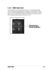
Stack Cool is a mini-PCB installed under the motherboard CPU socket to the motherboard. Stack Cool effectively lowers the motherboard temperature by as much as 10ºC. 2.2.3 ASUS Stack Cool The motherboard comes with ASUS Stack Cool, an innovative thermal solution that provides supplementary cooling to conduct heat away from motherboard components. Motherboard holes (for the CPU fan and heatsink assembly pins) ASUS P5GD2 2-3
Stack Cool is a mini-PCB installed under the motherboard CPU socket to the motherboard. Stack Cool effectively lowers the motherboard temperature by as much as 10ºC. 2.2.3 ASUS Stack Cool The motherboard comes with ASUS Stack Cool, an innovative thermal solution that provides supplementary cooling to conduct heat away from motherboard components. Motherboard holes (for the CPU fan and heatsink assembly pins) ASUS P5GD2 2-3

P5GD2 user's manual
Page 27
..., USBPW56, USBPW78) 3. Line Out port (lime) 7. PS/2 mouse port (green) Page 2-22 2-22 2-22 2-22 2-22 2-22 2-23 2-23 2-23 2-23 2-23 2-23 2-23 2-23 ASUS P5GD2 2-5 PCI slots 3. PCI Express slot Page 2-13 2-18 2-18 Jumpers 1. Side Speaker Out port (black) 5. USB 2.0 ports 3 and 4 10.
..., USBPW56, USBPW78) 3. Line Out port (lime) 7. PS/2 mouse port (green) Page 2-22 2-22 2-22 2-22 2-22 2-22 2-23 2-23 2-23 2-23 2-23 2-23 2-23 2-23 ASUS P5GD2 2-5 PCI slots 3. PCI Express slot Page 2-13 2-18 2-18 Jumpers 1. Side Speaker Out port (black) 5. USB 2.0 ports 3 and 4 10.
P5GD2 user's manual
Page 29
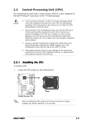
... • The product warranty does not cover damage to the PnP cap/socket pins/motherboard components. ASUS P5GD2 2-7 Contact your left. Locate the CPU socket on the motherboard. P5GD2 R P5GD2 Socket 775 Before installing the CPU, make sure that the socket box is facing towards you and ...resulting from incorrect CPU installation/removal, or misplacement/ loss/incorrect removal of the PnP cap. 2.3.1 Installling the CPU To install a CPU: 1. ASUS will shoulder the cost of repair only if the damage is shipment/ transit-related. • Keep the cap after installing the motherboard. 2.3...
... • The product warranty does not cover damage to the PnP cap/socket pins/motherboard components. ASUS P5GD2 2-7 Contact your left. Locate the CPU socket on the motherboard. P5GD2 R P5GD2 Socket 775 Before installing the CPU, make sure that the socket box is facing towards you and ...resulting from incorrect CPU installation/removal, or misplacement/ loss/incorrect removal of the PnP cap. 2.3.1 Installling the CPU To install a CPU: 1. ASUS will shoulder the cost of repair only if the damage is shipment/ transit-related. • Keep the cap after installing the motherboard. 2.3...
P5GD2 user's manual
Page 31
...-land package with Hyper-Threading Technology. • Hyper-Threading Technology is supported under Windows® XP/2003 Server and Linux 2.4.x (kernel) and later versions only. ASUS P5GD2 2-9 Notes on this motherboard: 1. DO NOT force the CPU into the retention tab. Install an Intel® Pentium® 4 CPU that supports Hyper-Threading Technology...
...-land package with Hyper-Threading Technology. • Hyper-Threading Technology is supported under Windows® XP/2003 Server and Linux 2.4.x (kernel) and later versions only. ASUS P5GD2 2-9 Notes on this motherboard: 1. DO NOT force the CPU into the retention tab. Install an Intel® Pentium® 4 CPU that supports Hyper-Threading Technology...
P5GD2 user's manual
Page 33
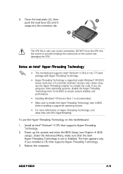
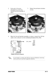
Rotate the push-pins clockwise to connect the CPU fan connector! CPU_FAN1 R P5GD2 CPU Fan connector Do not forget to lock. Hardware monitoring errors can occur if you fail to the connector on the motherboard labeled CPU_FAN1. P5GD2 GND CPU FAN PWR CPU FAN IN CPU FAN PWM 4. 2. When the fan and heatsink assembly is in place. 3. ASUS P5GD2 2-11 Push each of the pins downward to secure the heatsink and fan assembly in place, connect the CPU fan cable to plug this connector.
Rotate the push-pins clockwise to connect the CPU fan connector! CPU_FAN1 R P5GD2 CPU Fan connector Do not forget to lock. Hardware monitoring errors can occur if you fail to the connector on the motherboard labeled CPU_FAN1. P5GD2 GND CPU FAN PWR CPU FAN IN CPU FAN PWM 4. 2. When the fan and heatsink assembly is in place. 3. ASUS P5GD2 2-11 Push each of the pins downward to secure the heatsink and fan assembly in place, connect the CPU fan cable to plug this connector.

P5GD2 user's manual
Page 35
supports one pair of Dual-channel memory configuration. ASUS P5GD2 2-13 B - C - Single Sided D S - support for 4 modules inserted into the yellow and black slots as one module inserted into either the yellow slots or the black ...
supports one pair of Dual-channel memory configuration. ASUS P5GD2 2-13 B - C - Single Sided D S - support for 4 modules inserted into the yellow and black slots as one module inserted into either the yellow slots or the black ...
P5GD2 user's manual
Page 37
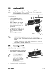
... the retaining clips outward to remove a DIMM. 1. Unlock a DIMM socket by pressing the retaining clips outward. 2. Remove the DIMM from the socket. 2 1 DDR2 DIMM notch ASUS P5GD2 2-15 Failure to do not support DDR DIMMs. DO not install DDR DIMMs to the DDR2 DIMM sockets. 2.4.4 Removing a DIMM Follow these steps to unlock...
... the retaining clips outward to remove a DIMM. 1. Unlock a DIMM socket by pressing the retaining clips outward. 2. Remove the DIMM from the socket. 2 1 DDR2 DIMM notch ASUS P5GD2 2-15 Failure to do not support DDR DIMMs. DO not install DDR DIMMs to the DDR2 DIMM sockets. 2.4.4 Removing a DIMM Follow these steps to unlock...
P5GD2 user's manual
Page 39
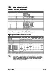
... not need IRQ assignments. Otherwise, conflicts will arise between the two PCI groups, making the system unstable and the card inoperable. shared shared -- shared - -- shared - - - - ASUS P5GD2 2-17 IRQ assignments for ISA or PCI devices. shared shared - shared - -- - shared shared shared shared shared shared - - - - 2.5.3 Interrupt assignments Standard interrupt assignments IRQ Priority 0 1 1 2 2 - 3 11...
... not need IRQ assignments. Otherwise, conflicts will arise between the two PCI groups, making the system unstable and the card inoperable. shared shared -- shared - -- shared - - - - ASUS P5GD2 2-17 IRQ assignments for ISA or PCI devices. shared shared - shared - -- - shared shared shared shared shared shared - - - - 2.5.3 Interrupt assignments Standard interrupt assignments IRQ Priority 0 1 1 2 2 - 3 11...

P5GD2 user's manual
Page 41
...Turn OFF the computer and unplug the power cord. 2. Remove the onboard battery. 3. The onboard button cell battery powers the RAM data in CMOS. P5GD2 R P5GD2 Clear RTC RAM CLRTC1 12 23 Normal (Default) Clear CMOS You do not need to clear the RTC when the system hangs due to pins... 1-2. 4. Shut down the key during the boot process and enter BIOS setup to pins 2-3. ASUS P5GD2 2-19 Plug the power cord and turn ON the computer. 6. For system failure due to default values. 2.6 Jumpers 1. Clear RTC RAM (CLRTC1) This ...
...Turn OFF the computer and unplug the power cord. 2. Remove the onboard battery. 3. The onboard button cell battery powers the RAM data in CMOS. P5GD2 R P5GD2 Clear RTC RAM CLRTC1 12 23 Normal (Default) Clear CMOS You do not need to clear the RTC when the system hangs due to pins... 1-2. 4. Shut down the key during the boot process and enter BIOS setup to pins 2-3. ASUS P5GD2 2-19 Plug the power cord and turn ON the computer. 6. For system failure due to default values. 2.6 Jumpers 1. Clear RTC RAM (CLRTC1) This ...

P5GD2 user's manual
Page 43
Keyboard power (3-pin KBPWR1) This jumper allows you press a key on the +5VSB lead, and a corresponding setting in the BIOS. KBPWR1 12 23 P5GD2 +5V +5VSB (Default) R P5GD2 Keyboard power setting ASUS P5GD2 2-21 Set this jumper to pins 2-3 (+5VSB) if you wish to enable or disable the keyboard wake-up the computer when you to wake up feature. 3. This feature requires an ATX power supply that can supply at least 1A on the keyboard (the default is the Space Bar).
Keyboard power (3-pin KBPWR1) This jumper allows you press a key on the +5VSB lead, and a corresponding setting in the BIOS. KBPWR1 12 23 P5GD2 +5V +5VSB (Default) R P5GD2 Keyboard power setting ASUS P5GD2 2-21 Set this jumper to pins 2-3 (+5VSB) if you wish to enable or disable the keyboard wake-up the computer when you to wake up feature. 3. This feature requires an ATX power supply that can supply at least 1A on the keyboard (the default is the Space Bar).

P5GD2 user's manual
Page 45
These two 4-pin Universal Serial Bus (USB) ports are available for connecting USB 2.0 devices. 1 0 . ASUS P5GD2 2-23 S / P D I F O u t p o r t . P S / 2 m o u s e p o r t ( g r e e n ) . Audio 2, 4, 6, or 8-channel configuration Port Light Blue Lime Pink Gray Black Yellow Orange Headset 2-channel Line In Line Out Mic In • • • 4-...
These two 4-pin Universal Serial Bus (USB) ports are available for connecting USB 2.0 devices. 1 0 . ASUS P5GD2 2-23 S / P D I F O u t p o r t . P S / 2 m o u s e p o r t ( g r e e n ) . Audio 2, 4, 6, or 8-channel configuration Port Light Blue Lime Pink Gray Black Yellow Orange Headset 2-channel Line In Line Out Mic In • • • 4-...

P5GD2 user's manual
Page 47
...set up to four IDE hard disk drives that you can be configured as a disk array through the onboard IDE RAID controller. R P5GD2 RAID connectors P5GD2 SEC_RAID1 PIN 1 PRI_RAID1 PIN 1 NOTE: Orient the red markings (usually zigzag) on how to set , make sure that can ... 133/100/66 signal cables. See section "4.4.6 Onboard Devices Configuration" for details on the IDE ribbon cable to Chapter 5 for details. ASUS P5GD2 2-25 These connectors are for Master/Slave jumper settings. These connectors support up RAID configurations. IDE RAID connectors (40-1 pin PRI_RAID1 [red...
...set up to four IDE hard disk drives that you can be configured as a disk array through the onboard IDE RAID controller. R P5GD2 RAID connectors P5GD2 SEC_RAID1 PIN 1 PRI_RAID1 PIN 1 NOTE: Orient the red markings (usually zigzag) on how to set , make sure that can ... 133/100/66 signal cables. See section "4.4.6 Onboard Devices Configuration" for details on the IDE ribbon cable to Chapter 5 for details. ASUS P5GD2 2-25 These connectors are for Master/Slave jumper settings. These connectors support up RAID configurations. IDE RAID connectors (40-1 pin PRI_RAID1 [red...
P5GD2 user's manual
Page 49
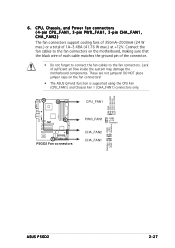
... not forget to connect the fan cables to the fan connectors. 6 . Connect the fan cables to the fan connectors on the fan connectors! • The ASUS Q-Fan2 function is supported using the CPU Fan (CPU_FAN1) and Chassis Fan 1 (CHA_FAN1) connectors only. CPU_FAN1 GND CPU FAN PWR CPU FAN IN CPU FAN...
... not forget to connect the fan cables to the fan connectors. 6 . Connect the fan cables to the fan connectors on the fan connectors! • The ASUS Q-Fan2 function is supported using the CPU Fan (CPU_FAN1) and Chassis Fan 1 (CHA_FAN1) connectors only. CPU_FAN1 GND CPU FAN PWR CPU FAN IN CPU FAN...
P5GD2 user's manual
Page 51
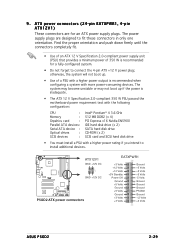
... Volts +5V Standby Power OK Ground +5 Volts Ground +5 Volts Ground +3 Volts +3 Volts Ground +5 Volts +5 Volts +5 Volts -5 Volts Ground Ground Ground PSON# Ground -12 Volts +3 Volts ASUS P5GD2 2-29 The power supply plugs are for a fully-configured system. • Do not forget to fit these connectors in only one orientation. 9 .
... Volts +5V Standby Power OK Ground +5 Volts Ground +5 Volts Ground +3 Volts +3 Volts Ground +5 Volts +5 Volts +5 Volts -5 Volts Ground Ground Ground PSON# Ground -12 Volts +3 Volts ASUS P5GD2 2-29 The power supply plugs are for a fully-configured system. • Do not forget to fit these connectors in only one orientation. 9 .

P5GD2 user's manual
Page 53
... audio features. • The default setting of the chassis intrusion sensor or switch cable to this connector. CHASSIS1 +5VSB_MB Chassis Signal GND P5GD2 P5GD2 Chassis alarm lead (Default) 13. See page 4-27. By default, the pins labeled "Chassis Signal" and "Ground" are shorted with...r o n t P a n e l S u p p o r t T y p e in the BIOS to this connector. Front panel audio connector (10-1 pin AAFP) This connector is removed or replaced. ASUS P5GD2 2-31 12. Chassis intrusion connector (4-1 pin CHASSIS1) This connector is then generated as a chassis intrusion event.
... audio features. • The default setting of the chassis intrusion sensor or switch cable to this connector. CHASSIS1 +5VSB_MB Chassis Signal GND P5GD2 P5GD2 Chassis alarm lead (Default) 13. See page 4-27. By default, the pins labeled "Chassis Signal" and "Ground" are shorted with...r o n t P a n e l S u p p o r t T y p e in the BIOS to this connector. Front panel audio connector (10-1 pin AAFP) This connector is removed or replaced. ASUS P5GD2 2-31 12. Chassis intrusion connector (4-1 pin CHASSIS1) This connector is then generated as a chassis intrusion event.


