User Manual
Page 3
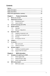
... Safety information vii P5G41-M SI specifications summary viii Chapter 1: Product introduction 1.1 Before you proceed 1-1 1.2 Motherboard overview 1-2 1.2.1 Motherboard layout 1-2 1.2.2 Layout contents 1-2 1.3 Central Processing Unit (CPU 1-3 1.4 System memory 1-3 1.4.1 Overview 1-3 1.4.2 Memory configurations 1-4 1.5 Expansion slots 1-6 1.5.1 Installing an expansion card 1-6 1.5.2 Configuring an expansion card 1-7 1.5.3 PCI slots 1-7 1.5.4 PCI Express x16 slot 1-7 1.6 Jumpers 1-7 1.7 Connectors 1-9 1.7.1 Rear panel ports 1-9 1.7.2 Internal connectors 1-10 1.8 Software...
... Safety information vii P5G41-M SI specifications summary viii Chapter 1: Product introduction 1.1 Before you proceed 1-1 1.2 Motherboard overview 1-2 1.2.1 Motherboard layout 1-2 1.2.2 Layout contents 1-2 1.3 Central Processing Unit (CPU 1-3 1.4 System memory 1-3 1.4.1 Overview 1-3 1.4.2 Memory configurations 1-4 1.5 Expansion slots 1-6 1.5.1 Installing an expansion card 1-6 1.5.2 Configuring an expansion card 1-7 1.5.3 PCI slots 1-7 1.5.4 PCI Express x16 slot 1-7 1.6 Jumpers 1-7 1.7 Connectors 1-9 1.7.1 Rear panel ports 1-9 1.7.2 Internal connectors 1-10 1.8 Software...

User Manual
Page 6
... environments with the product, contact a qualified service technician or your dealer immediately. • To avoid short circuits, keep paper clips, screws, and staples away from connectors, slots, sockets and circuitry. • Avoid dust, humidity, and temperature extremes. INVISIBLE LASER RADIATION, AVOID EXPOSURE TO BEAM. • Never dispose of the electrical outlet...
... environments with the product, contact a qualified service technician or your dealer immediately. • To avoid short circuits, keep paper clips, screws, and staples away from connectors, slots, sockets and circuitry. • Avoid dust, humidity, and temperature extremes. INVISIBLE LASER RADIATION, AVOID EXPOSURE TO BEAM. • Never dispose of the electrical outlet...
User Manual
Page 8
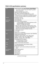
...ECC DDR2 800/667MHz memory modules - P5G41-M SI specifications summary CPU Chipset System bus Memory Expansion slots VGA Storage LAN Audio USB ASUS Special features LGA775 Socket for Intel&#...) Supports Microsoft® DirectX 10 D-SUB Max. resolution: 2048 x 1536 x 32Bpp @75Hz DVI Max. resolution: 1920 x 1200 x 32Bpp @60Hz HDMI Max. We recommend a maximum of 4GB... 1920 x 1080 @60Hz Southbridge Intel® ICH7 supports: 4 x Serial ATA 3Gb/s connectors 1 x UltraDMA 100/66 connector Realtek® 8112L PCIe Gb LAN controller VT1708S High Definition Audio 6-channel CODEC Supports Multi-...
...ECC DDR2 800/667MHz memory modules - P5G41-M SI specifications summary CPU Chipset System bus Memory Expansion slots VGA Storage LAN Audio USB ASUS Special features LGA775 Socket for Intel&#...) Supports Microsoft® DirectX 10 D-SUB Max. resolution: 2048 x 1536 x 32Bpp @75Hz DVI Max. resolution: 1920 x 1200 x 32Bpp @60Hz HDMI Max. We recommend a maximum of 4GB... 1920 x 1080 @60Hz Southbridge Intel® ICH7 supports: 4 x Serial ATA 3Gb/s connectors 1 x UltraDMA 100/66 connector Realtek® 8112L PCIe Gb LAN controller VT1708S High Definition Audio 6-channel CODEC Supports Multi-...
User Manual
Page 9
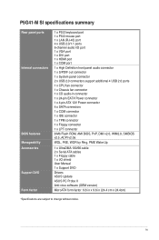
P5G41-M SI specifications summary Rear panel ports Internal connectors BIOS features Manageability Accessories Support DVD Form factor 1 x PS/2 keyboard port 1 x PS/2 mouse port 1 x LAN (RJ-45) port 4 x USB 2.0/1.1 ports 6-channel audio I/O port 1 x VGA port 1 x DVI port 1 x HDMI port 1 x COM port 1 x High Definition front panel audio connector 1 x S/PDIF out connector 1 x System panel connector 2 x USB 2.0 connectors support additional 4 USB 2.0 ports 1 x CPU...
P5G41-M SI specifications summary Rear panel ports Internal connectors BIOS features Manageability Accessories Support DVD Form factor 1 x PS/2 keyboard port 1 x PS/2 mouse port 1 x LAN (RJ-45) port 4 x USB 2.0/1.1 ports 6-channel audio I/O port 1 x VGA port 1 x DVI port 1 x HDMI port 1 x COM port 1 x High Definition front panel audio connector 1 x S/PDIF out connector 1 x System panel connector 2 x USB 2.0 connectors support additional 4 USB 2.0 ports 1 x CPU...

User Manual
Page 11
... Place this side towards the rear of the chassis. Keyboard power (3-pin KBPWR) 2. USB device wake-up (3-pin USBPW1-4, USBPW5-8) 3. TPM connector (20-1 pin TPM) Page Connectors/Jumpers/Slots/LED 1-8 11. USB connectors (10-1 pin USB56, USB78) 1-12 1-12 15. Digital audio connector (4-1 pin SPDIF_OUT) 1-15 1-14 18. System panel connector (10-1 pin F_PANEL) 1-14 ASUS P5G41-M SI 1-2
... Place this side towards the rear of the chassis. Keyboard power (3-pin KBPWR) 2. USB device wake-up (3-pin USBPW1-4, USBPW5-8) 3. TPM connector (20-1 pin TPM) Page Connectors/Jumpers/Slots/LED 1-8 11. USB connectors (10-1 pin USB56, USB78) 1-12 1-12 15. Digital audio connector (4-1 pin SPDIF_OUT) 1-15 1-14 18. System panel connector (10-1 pin F_PANEL) 1-14 ASUS P5G41-M SI 1-2
User Manual
Page 15
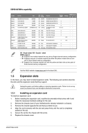
...two pairs of 2) 1024MB 2048MB 2048MB 1024MB 2048MB 1024MB 1024MB 4096MB SS/ Chip DS Brand Chip No. ASUS P5G41-M SI 1-6 Failure to do so may need to install expansion cards. Align the card connector with the screw. 6. Remove the chassis cover (if your motherboard is completely seated on the slot. ... and damage motherboard components. 1.5.1 Installing an expansion card To install an expansion card: 1. Secure the card to use. 4. Visit the ASUS website at www.asus.com for the card. 2. Double - DS ADATA SS Apacer SS Apacer DS Corsair DS G.SKILL DS GEIL DS GEIL DS GEIL SS...
...two pairs of 2) 1024MB 2048MB 2048MB 1024MB 2048MB 1024MB 1024MB 4096MB SS/ Chip DS Brand Chip No. ASUS P5G41-M SI 1-6 Failure to do so may need to install expansion cards. Align the card connector with the screw. 6. Remove the chassis cover (if your motherboard is completely seated on the slot. ... and damage motherboard components. 1.5.1 Installing an expansion card To install an expansion card: 1. Secure the card to use. 4. Visit the ASUS website at www.asus.com for the card. 2. Double - DS ADATA SS Apacer SS Apacer DS Corsair DS G.SKILL DS GEIL DS GEIL DS GEIL SS...
User Manual
Page 18
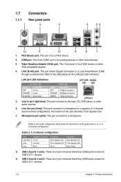
... connects to USB 2.0/1.1 devices. 9. Refer to the audio configuration table below for a PS/2 mouse. 2. This 15-pin port is for the LAN port LED indicators. 1.7 Connectors 1.7.1 Rear panel ports 1 2 3 4 56 12 11 10 9 8 7 1.
... connects to USB 2.0/1.1 devices. 9. Refer to the audio configuration table below for a PS/2 mouse. 2. This 15-pin port is for the LAN port LED indicators. 1.7 Connectors 1.7.1 Rear panel ports 1 2 3 4 56 12 11 10 9 8 7 1.
User Manual
Page 19
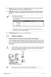
... PWR CPU FAN IN CPU FAN PWM P5G41-M SI CHA_FAN GND +12V Rotation P5G41-M SI fan connectors Only the 4-pin CPU fan connector supports the ASUS Q-FAN feature. 10. DVI port. This port is for a PS/2 keyboard. 1.7.2 Internal connectors 1. DVI-D can't be converted to output RGB Signal to the fan connectors on the fan connectors. Insufficient air flow inside the system may...
... PWR CPU FAN IN CPU FAN PWM P5G41-M SI CHA_FAN GND +12V Rotation P5G41-M SI fan connectors Only the 4-pin CPU fan connector supports the ASUS Q-FAN feature. 10. DVI port. This port is for a PS/2 keyboard. 1.7.2 Internal connectors 1. DVI-D can't be converted to output RGB Signal to the fan connectors on the fan connectors. Insufficient air flow inside the system may...
User Manual
Page 20
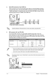
...GND RSATA_RXP1 RSATA_RXN1 GND P5G41-M SI SATA connectors Install the Windows® XP Service Pack 2 or later version before using Serial ATA. 3. P5G41-M SI IDE connector 1-11 Chapter 1: Product introduction 2. Serial ATA connectors (7-pin SATA1-4) These connectors are three connectors on the IDE connector is set as "Cable...-conductor IDE cable for Serial ATA 3Gb/s hard disk and optical disk drives. PRI_IDE P5G41-M SI PIN1 NOTE:Orient the red markings on the Ultra DMA cable connector. The Serial ATA 3Gb/s is backward compatible with 133MB/s (Ultra DMA133). Master Slave...
...GND RSATA_RXP1 RSATA_RXN1 GND P5G41-M SI SATA connectors Install the Windows® XP Service Pack 2 or later version before using Serial ATA. 3. P5G41-M SI IDE connector 1-11 Chapter 1: Product introduction 2. Serial ATA connectors (7-pin SATA1-4) These connectors are three connectors on the IDE connector is set as "Cable...-conductor IDE cable for Serial ATA 3Gb/s hard disk and optical disk drives. PRI_IDE P5G41-M SI PIN1 NOTE:Orient the red markings on the Ultra DMA cable connector. The Serial ATA 3Gb/s is backward compatible with 133MB/s (Ultra DMA133). Master Slave...
User Manual
Page 21
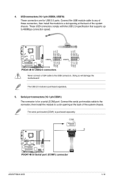
... 1 USB+5V USB_P7USB_P7+ GND USB+5V USB_P5USB_P5+ GND P5G41-M SI USB2.0 connectors Never connect a 1394 cable to 480Mbps connection speed. COM1 PIN 1 P5G41-M SI P5G41-M SI Serial port (COM1) connector ASUS P5G41-M SI 1-12 Doing so will damage the motherboard! Serial port connectors (10-1 pin COM1) The connector is for USB 2.0 ports. USB connectors (10-1 pin USB56, USB78) These connectors are for a serial (COM) port.
... 1 USB+5V USB_P7USB_P7+ GND USB+5V USB_P5USB_P5+ GND P5G41-M SI USB2.0 connectors Never connect a 1394 cable to 480Mbps connection speed. COM1 PIN 1 P5G41-M SI P5G41-M SI Serial port (COM1) connector ASUS P5G41-M SI 1-12 Doing so will damage the motherboard! Serial port connectors (10-1 pin COM1) The connector is for USB 2.0 ports. USB connectors (10-1 pin USB56, USB78) These connectors are for a serial (COM) port.

User Manual
Page 22
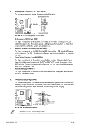
...-pin power plug can provide at http://support.asus. Optical drive audio in only one orientation. ATX12V EATXPWR +12V DC +12V DC P5G41-M SI GND GND +3 Volts +12 Volts +12 Volts +5V Standby Power OK PIN 1 GND +5 Volts GND +5 Volts GND +3 Volts +3 Volts PIN 1 P5G41-M SI ATX power connectors GND +5 Volts +5 Volts +5 Volts -5 Volts GND GND...
...-pin power plug can provide at http://support.asus. Optical drive audio in only one orientation. ATX12V EATXPWR +12V DC +12V DC P5G41-M SI GND GND +3 Volts +12 Volts +12 Volts +5V Standby Power OK PIN 1 GND +5 Volts GND +5 Volts GND +3 Volts +3 Volts PIN 1 P5G41-M SI ATX power connectors GND +5 Volts +5 Volts +5 Volts -5 Volts GND GND...
User Manual
Page 23
... F_LAD2 S_SMBCLIK_MAIN S_SMBCLIK_MAIN GND PIN 1 The TPM module is for the system power LED. TPM connector (20-1 pin TPM) This connector supports a Trusted Platform Module (TPM) system, which can securely store keys, digital certificates, passwords, and data. ASUS P5G41-M SI 1-14 Connect the chassis power LED cable to the HDD. • Power/Soft-off the...
... F_LAD2 S_SMBCLIK_MAIN S_SMBCLIK_MAIN GND PIN 1 The TPM module is for the system power LED. TPM connector (20-1 pin TPM) This connector supports a Trusted Platform Module (TPM) system, which can securely store keys, digital certificates, passwords, and data. ASUS P5G41-M SI 1-14 Connect the chassis power LED cable to the HDD. • Power/Soft-off the...
User Manual
Page 24
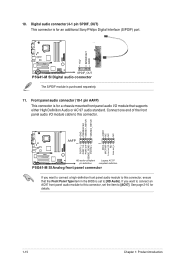
... Chapter 1: Product introduction Front panel audio connector (10-1 pin AAFP) This connector is purchased separately. 11. See page 2-10 for an additional Sony/Philips Digital Interface (S/PDIF) port. +5V SPDIFOUT GND P5G41-M SI SPDIF_OUT P5G41-M SI Digital audio connector The S/PDIF module is for a chassis...-mounted front panel audio I /O module cable to this connector, set to [AC97]. If you want to connect an AC97 ...
... Chapter 1: Product introduction Front panel audio connector (10-1 pin AAFP) This connector is purchased separately. 11. See page 2-10 for an additional Sony/Philips Digital Interface (S/PDIF) port. +5V SPDIFOUT GND P5G41-M SI SPDIF_OUT P5G41-M SI Digital audio connector The S/PDIF module is for a chassis...-mounted front panel audio I /O module cable to this connector, set to [AC97]. If you want to connect an AC97 ...
User Manual
Page 25
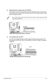
...compatible computers. P5G41-M SI Floppy disk drive connector 13. 12. LPT AFD ERR# INIT# SLIN# GND GND GND GND GND GND GND GND PIN 1 STB# PD0 PD1 PD2 PD3 PD4 PD5 PD6 PD7 ACK# BUSY PE SLCT P5G41-M SI P5G41-M SI Parallel Port Connector ASUS P5G41-M SI 1-16 Pin 5 on the connector is the ...parallel port interface on the floppy ribbon cable to the signal connector at the back of the cable to this connector, then connect the other end to PIN 1. Insert...
...compatible computers. P5G41-M SI Floppy disk drive connector 13. 12. LPT AFD ERR# INIT# SLIN# GND GND GND GND GND GND GND GND PIN 1 STB# PD0 PD1 PD2 PD3 PD4 PD5 PD6 PD7 ACK# BUSY PE SLCT P5G41-M SI P5G41-M SI Parallel Port Connector ASUS P5G41-M SI 1-16 Pin 5 on the connector is the ...parallel port interface on the floppy ribbon cable to the signal connector at the back of the cable to this connector, then connect the other end to PIN 1. Insert...
User Manual
Page 29
... the BIOS file to the USB port or to the floppy disk drive, if supported. 3. Recovering the BIOS To recover the BIOS: 1. ASUS P5G41-M SI 2-3 Insert the support DVD to the optical drive or the removable device that allows you to restore the BIOS file when it fails or gets... The BIOS file in the support DVD may not be the latest version. Refer to ensure system compatibility and stability. For motherboards without the floppy connector, prepare a USB flash disk before using this utility. Ensure to load the BIOS default settings to section 2.8 Exit Menu for the BIOS file...
... the BIOS file to the USB port or to the floppy disk drive, if supported. 3. Recovering the BIOS To recover the BIOS: 1. ASUS P5G41-M SI 2-3 Insert the support DVD to the optical drive or the removable device that allows you to restore the BIOS file when it fails or gets... The BIOS file in the support DVD may not be the latest version. Refer to ensure system compatibility and stability. For motherboards without the floppy connector, prepare a USB flash disk before using this utility. Ensure to load the BIOS default settings to section 2.8 Exit Menu for the BIOS file...


