

User Manual
Page 1
P5G41-M EVO Motherboard
P5G41-M EVO Motherboard
User Manual
Page 3
Contents Notices...v Safety information vi Safety information vii P5G41-M EVO specifications summary viii Chapter 1: Product introduction 1.1 Before you proceed 1-1 1.2 Motherboard overview 1-2 1.2.1 Motherboard layout 1-2 1.2.2 Layout contents 1-2 1.3 Central Processing Unit (CPU 1-3 1.4 System memory 1-3 1.4.1 Overview 1-3 1.4.2 Memory configurations 1-4 1.5... 1-18 Chapter 1: BIOS information 2.1 Managing and updating your BIOS 2-1 2.1.1 ASUS Update utility 2-1 2.1.2 ASUS EZ Flash 2 utility 2-2 2.1.3 ASUS CrashFree BIOS 2-3 2.2 BIOS setup program 2-4 2.3 Main menu 2-4 iii
Contents Notices...v Safety information vi Safety information vii P5G41-M EVO specifications summary viii Chapter 1: Product introduction 1.1 Before you proceed 1-1 1.2 Motherboard overview 1-2 1.2.1 Motherboard layout 1-2 1.2.2 Layout contents 1-2 1.3 Central Processing Unit (CPU 1-3 1.4 System memory 1-3 1.4.1 Overview 1-3 1.4.2 Memory configurations 1-4 1.5... 1-18 Chapter 1: BIOS information 2.1 Managing and updating your BIOS 2-1 2.1.1 ASUS Update utility 2-1 2.1.2 ASUS EZ Flash 2 utility 2-2 2.1.3 ASUS CrashFree BIOS 2-3 2.2 BIOS setup program 2-4 2.3 Main menu 2-4 iii
User Manual
Page 5
... by turning the equipment off and on a circuit different from digital apparatus set out in our products at ASUS REACH website at http://green.asus.com/english/REACH.htm. The use of shielded cables for connection of the monitor to the graphics card is... occur in municipal waste. These limits are designed to provide reasonable protection against harmful interference in municipal waste. DO NOT throw the motherboard in a residential installation. DO NOT throw the mercury-containing button cell battery in a particular installation. Check local regulations for disposal of...
... by turning the equipment off and on a circuit different from digital apparatus set out in our products at ASUS REACH website at http://green.asus.com/english/REACH.htm. The use of shielded cables for connection of the monitor to the graphics card is... occur in municipal waste. These limits are designed to provide reasonable protection against harmful interference in municipal waste. DO NOT throw the motherboard in a residential installation. DO NOT throw the mercury-containing button cell battery in a particular installation. Check local regulations for disposal of...
User Manual
Page 6
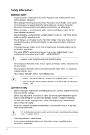
... is an optional component (may or may become wet. Operation safety • Before installing the motherboard and adding devices on a stable surface. • If you encounter technical problems with your motherboard) and is broken, do not try to a hazardous material collection point. • Never replace...may not be used in your dealer immediately. • To avoid short circuits, keep paper clips, screws, and staples away from the motherboard, ensure that came with an incorrect battery type. • RISK OF EXPLOSION IF BATTERY IS REPLACED BY AN INCORRECT TYPE. • DISPOSE...
... is an optional component (may or may become wet. Operation safety • Before installing the motherboard and adding devices on a stable surface. • If you encounter technical problems with your motherboard) and is broken, do not try to a hazardous material collection point. • Never replace...may not be used in your dealer immediately. • To avoid short circuits, keep paper clips, screws, and staples away from the motherboard, ensure that came with an incorrect battery type. • RISK OF EXPLOSION IF BATTERY IS REPLACED BY AN INCORRECT TYPE. • DISPOSE...

User Manual
Page 7
... power supply is set to find more keys simultaneously, the key names are linked with a plus sign (+). ASUS websites The ASUS website provides updated information on ASUS hardware and software products. Conventions used throughout this guide To make sure that the power cables for product and ... that all power cables from the existing system before you add a device. • Before connecting or removing signal cables from the motherboard, ensure that may have been added by your area. Safety information Electrical safety • To prevent electrical shock hazard, disconnect the ...
... power supply is set to find more keys simultaneously, the key names are linked with a plus sign (+). ASUS websites The ASUS website provides updated information on ASUS hardware and software products. Conventions used throughout this guide To make sure that the power cables for product and ... that all power cables from the existing system before you add a device. • Before connecting or removing signal cables from the motherboard, ensure that may have been added by your area. Safety information Electrical safety • To prevent electrical shock hazard, disconnect the ...

User Manual
Page 11
... start installing the motherboard, and hardware devices on it on them. • Whenever you must shut down the system and unplug the power cable before removing or plugging in your retailer. 1.1 Before you proceed Take note of the onboard LED. SB_PWR P5G41-M EVO ON OFF Standby Power Powered Off P5G41-M EVO Onboard LED ASUS P5G41-M EVO 1-1 This is...
... start installing the motherboard, and hardware devices on it on them. • Whenever you must shut down the system and unplug the power cable before removing or plugging in your retailer. 1.1 Before you proceed Take note of the onboard LED. SB_PWR P5G41-M EVO ON OFF Standby Power Powered Off P5G41-M EVO Onboard LED ASUS P5G41-M EVO 1-1 This is...

User Manual
Page 12
... 1-1 ATX12V) 4. LPT connector (26-1 pin LPT) 1-17 6. Digital audio connector (4-1 pin SPDIF_OUT) 1-15 8. Doing so can damage the motherboard. 1.2.2 Layout contents Connectors/Jumpers/Slots/LED Page Connectors/Jumpers/Slots/LED 1. IDE connector (40-1 pin PRI_IDE) 1-12 3. CPU and Chassis fan ... CHA_FAN LGA775 USB34 USBPW1-4 LAN1_USB12 RTL 8112L COM1 AUDIO CHASSIS ICS 9LPRS441 PCIEX16 Intel® G41 Super I/O PCI1 P5G41-M EVO PCI2 VIA VT1708S CD AAFP SPDIF_OUT PCI3 FLOPPY LPT Lithium Cell CMOS Power Intel® ICH7 SATA4 SATA3 SATA2 SATA1 ...
... 1-1 ATX12V) 4. LPT connector (26-1 pin LPT) 1-17 6. Digital audio connector (4-1 pin SPDIF_OUT) 1-15 8. Doing so can damage the motherboard. 1.2.2 Layout contents Connectors/Jumpers/Slots/LED Page Connectors/Jumpers/Slots/LED 1. IDE connector (40-1 pin PRI_IDE) 1-12 3. CPU and Chassis fan ... CHA_FAN LGA775 USB34 USBPW1-4 LAN1_USB12 RTL 8112L COM1 AUDIO CHASSIS ICS 9LPRS441 PCIEX16 Intel® G41 Super I/O PCI1 P5G41-M EVO PCI2 VIA VT1708S CD AAFP SPDIF_OUT PCI3 FLOPPY LPT Lithium Cell CMOS Power Intel® ICH7 SATA4 SATA3 SATA2 SATA1 ...

User Manual
Page 13
... on the socket and the socket contacts are unplugged before installing the CPU. • Upon purchase of the DDR2 DIMM sockets: DIMM_A1 DIMM_A2 DIMM_B1 DIMM_B2 P5G41-M EVO P5G41-M EVO 240-pin DDR2 DIMM sockets ASUS P5G41-M EVO 1-3 This motherboard supports Intel® Hyper-Threading Technology and Enhanced Intel SpeedStep® Technology (EIST). 1.4 System memory 1.4.1 Overview This...
... on the socket and the socket contacts are unplugged before installing the CPU. • Upon purchase of the DDR2 DIMM sockets: DIMM_A1 DIMM_A2 DIMM_B1 DIMM_B2 P5G41-M EVO P5G41-M EVO 240-pin DDR2 DIMM sockets ASUS P5G41-M EVO 1-3 This motherboard supports Intel® Hyper-Threading Technology and Enhanced Intel SpeedStep® Technology (EIST). 1.4 System memory 1.4.1 Overview This...

User Manual
Page 14
...65533;�a�c�h��s�lo�t�. • The default memory operation frequency is dependent on the motherboard, the actual usable memory for the dual-channel configuration. Use a 64-bit Windows® OS if you want ...8226; Heat-Sink Package 5 •• Heat-Sink Package 5 •• continued on W�in Channel A and Channel B. or - P5G41-M EVO Motherboard Qualified Vendors List (QVL) DDR2-800MHz capability Vendor Part No. 1.4.2 Memory configurations You may install a 512MB, 1GB, and 2GB unbuffered non-ECC DDR2...
...65533;�a�c�h��s�lo�t�. • The default memory operation frequency is dependent on the motherboard, the actual usable memory for the dual-channel configuration. Use a 64-bit Windows® OS if you want ...8226; Heat-Sink Package 5 •• Heat-Sink Package 5 •• continued on W�in Channel A and Channel B. or - P5G41-M EVO Motherboard Qualified Vendors List (QVL) DDR2-800MHz capability Vendor Part No. 1.4.2 Memory configurations You may install a 512MB, 1GB, and 2GB unbuffered non-ECC DDR2...

User Manual
Page 17
...Chip Brand Chip No. Before installing the expansion card, read the documentation that they support. Remove the chassis cover (if your motherboard is completely seated on the slot. 5. Single-sided / DS - sided DIMM support: • A*: Supports one module inserted...; 5 • •• SS - Align the card connector with the screw. 6. DDR2-667MHz capability Vendor Part No. Visit the ASUS website at www.asus.com for the card. 2. Unplug the power cord before adding or removing expansion cards. Failure to use. 4. Replace the chassis cover. ASUS P5G41-M EVO 1-7
...Chip Brand Chip No. Before installing the expansion card, read the documentation that they support. Remove the chassis cover (if your motherboard is completely seated on the slot. 5. Single-sided / DS - sided DIMM support: • A*: Supports one module inserted...; 5 • •• SS - Align the card connector with the screw. 6. DDR2-667MHz capability Vendor Part No. Visit the ASUS website at www.asus.com for the card. 2. Unplug the power cord before adding or removing expansion cards. Failure to use. 4. Replace the chassis cover. ASUS P5G41-M EVO 1-7
User Manual
Page 18
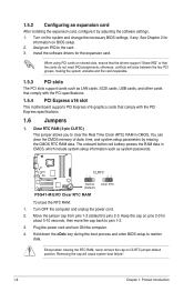
... such as LAN cards, SCSI cards, USB cards, and other cards that comply with the PCI specifications. 1.5.4 PCI Express x16 slot This motherboard supports PCI Express x16 graphics cards that the cards do not need IRQ assignments; Clear RTC RAM (3-pin CLRTC) This jumper allows you to...RTC RAM, never remove the cap on BIOS setup. 2. See Chapter 2 for information on CLRTC jumper default position. CLRTC 12 23 P5G41-M EVO Normal (Default) Clear RTC P5G41-M EVO Clear RTC RAM To erase the RTC RAM: 1. Removing the cap will arise between the two PCI groups, making the system unstable...
... such as LAN cards, SCSI cards, USB cards, and other cards that comply with the PCI specifications. 1.5.4 PCI Express x16 slot This motherboard supports PCI Express x16 graphics cards that the cards do not need IRQ assignments; Clear RTC RAM (3-pin CLRTC) This jumper allows you to...RTC RAM, never remove the cap on BIOS setup. 2. See Chapter 2 for information on CLRTC jumper default position. CLRTC 12 23 P5G41-M EVO Normal (Default) Clear RTC P5G41-M EVO Clear RTC RAM To erase the RTC RAM: 1. Removing the cap will arise between the two PCI groups, making the system unstable...
User Manual
Page 21
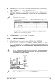
...This port is for a High-Definition Multimedia Interface (HDMI) connector, and is for any DVI-D compatible device. ASUS P5G41-M EVO 1-11 This port is HDCP compliant allowing playback of HD DVD, Blu-Ray and other protected content. HDMI port...P5G41-M EVO CHA_FAN GND +12V Rotation P5G41-M EVO fan connectors Only the 4-pin CPU fan connector supports the ASUS Q-FAN feature. Dual display output support • This table indicates that the black wire of each cable matches the ground pin of 1 A ~ 7 A (84 W max.) at +12V. Insufficient air flow inside the system may damage the motherboard...
...This port is for a High-Definition Multimedia Interface (HDMI) connector, and is for any DVI-D compatible device. ASUS P5G41-M EVO 1-11 This port is HDCP compliant allowing playback of HD DVD, Blu-Ray and other protected content. HDMI port...P5G41-M EVO CHA_FAN GND +12V Rotation P5G41-M EVO fan connectors Only the 4-pin CPU fan connector supports the ASUS Q-FAN feature. Dual display output support • This table indicates that the black wire of each cable matches the ground pin of 1 A ~ 7 A (84 W max.) at +12V. Insufficient air flow inside the system may damage the motherboard...

User Manual
Page 22
... 3Gb/s is set as "Cable-Select", ensure that all other device jumpers have the same setting. Connect the blue connector to the motherboard's IDE connector, then select one of device(s) - If any device jumper is faster than the standard parallel ATA with Serial ATA 1.... GND GND RSATA_TXP3 RSATA_TXN3 GND RSATA_RXP3 RSATA_RXN3 GND GND RSATA_TXP2 RSATA_TXN2 GND RSATA_RXP2 RSATA_RXN2 GND GND RSATA_TXP1 RSATA_TXN1 GND RSATA_RXP1 RSATA_RXN1 GND P5G41-M EVO SATA connectors Install the Windows® XP Service Pack 2 or later version before using Serial ATA. 3. This prevents incorrect ...
... 3Gb/s is set as "Cable-Select", ensure that all other device jumpers have the same setting. Connect the blue connector to the motherboard's IDE connector, then select one of device(s) - If any device jumper is faster than the standard parallel ATA with Serial ATA 1.... GND GND RSATA_TXP3 RSATA_TXN3 GND RSATA_RXP3 RSATA_RXN3 GND GND RSATA_TXP2 RSATA_TXN2 GND RSATA_RXP2 RSATA_RXN2 GND GND RSATA_TXP1 RSATA_TXN1 GND RSATA_RXP1 RSATA_RXN1 GND P5G41-M EVO SATA connectors Install the Windows® XP Service Pack 2 or later version before using Serial ATA. 3. This prevents incorrect ...
User Manual
Page 23
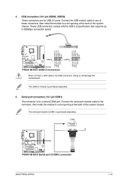
.... Doing so will damage the motherboard! 4. Connect the USB module cable to any of these connectors, then install the module to a slot opening at the back of the system chassis. COM1 PIN 1 P5G41-M EVO P5G41-M EVO Serial port (COM1) connector ASUS P5G41-M EVO 1-13 The serial port bracket ...(COM1) is purchased separately. USB+5V USB_P8USB_P8+ GND NC USB+5V USB_P6USB_P6+ GND NC P5G41-M EVO USB56 PIN 1 USB78 PIN 1 USB+5V USB_P7USB_P7+ ...
.... Doing so will damage the motherboard! 4. Connect the USB module cable to any of these connectors, then install the module to a slot opening at the back of the system chassis. COM1 PIN 1 P5G41-M EVO P5G41-M EVO Serial port (COM1) connector ASUS P5G41-M EVO 1-13 The serial port bracket ...(COM1) is purchased separately. USB+5V USB_P8USB_P8+ GND NC USB+5V USB_P6USB_P6+ GND NC P5G41-M EVO USB56 PIN 1 USB78 PIN 1 USB+5V USB_P7USB_P7+ ...

User Manual
Page 28
...icon to display Support DVD/ motherboard information Click an item to your hardware. • Motherboard settings and hardware options vary. Double-click ASSETUP.EXE to get all motherboard features. To run the DVD. 1-18 Chapter 1: Product introduction Visit the ASUS website at any time without notice... the features of the Support DVD are subject to change at www.asus.com for better compatibility and system stability. 1.8.2 Support DVD information The Support DVD that comes with the motherboard package contains drivers, software applications, and utilities that you can install ...
...icon to display Support DVD/ motherboard information Click an item to your hardware. • Motherboard settings and hardware options vary. Double-click ASSETUP.EXE to get all motherboard features. To run the DVD. 1-18 Chapter 1: Product introduction Visit the ASUS website at any time without notice... the features of the Support DVD are subject to change at www.asus.com for better compatibility and system stability. 1.8.2 Support DVD information The Support DVD that comes with the motherboard package contains drivers, software applications, and utilities that you can install ...
User Manual
Page 29
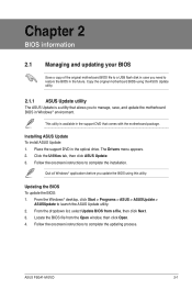
... is a utility that comes with the motherboard package. Click the Utilities tab, then click ASUS Update. 3. From the Windows® desktop, click Start > Programs > ASUS > ASUSUpdate > ASUSUpdate to complete the ...ASUS Update To install ASUS Update: 1. From the dropdown list, select Update BIOS from the Open window, then click Open. 4. Follow the onscreen instructions to launch the ASUS Update utility. 2. Place the support DVD in the optical drive. Updating the BIOS To update the BIOS: 1. Follow the onscreen instructions to complete the installation. ASUS P5G41-M EVO...
... is a utility that comes with the motherboard package. Click the Utilities tab, then click ASUS Update. 3. From the Windows® desktop, click Start > Programs > ASUS > ASUSUpdate > ASUSUpdate to complete the ...ASUS Update To install ASUS Update: 1. From the dropdown list, select Update BIOS from the Open window, then click Open. 4. Follow the onscreen instructions to launch the ASUS Update utility. 2. Place the support DVD in the optical drive. Updating the BIOS To update the BIOS: 1. Follow the onscreen instructions to complete the installation. ASUS P5G41-M EVO...
User Manual
Page 31
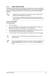
Download the latest BIOS file from the ASUS website at www.asus.com. • The removable device that ASUS CrashFree BIOS support vary with motherboard models. Insert the support DVD to the optical drive or the removable device that contains the BIOS file to the USB...To recover the BIOS: 1. Turn on again. Doing so can restore a corrupted BIOS file using this utility. ASUS P5G41-M EVO 2-3 For motherboards without the floppy connector, prepare a USB flash disk before using the motherboard support DVD or a removable device that contains the updated BIOS file. • The BIOS file in the ...
Download the latest BIOS file from the ASUS website at www.asus.com. • The removable device that ASUS CrashFree BIOS support vary with motherboard models. Insert the support DVD to the optical drive or the removable device that contains the BIOS file to the USB...To recover the BIOS: 1. Turn on again. Doing so can restore a corrupted BIOS file using this utility. ASUS P5G41-M EVO 2-3 For motherboards without the floppy connector, prepare a USB flash disk before using the motherboard support DVD or a removable device that contains the updated BIOS file. • The BIOS file in the ...

User Manual
Page 32
... system. We recommend to always shut down the system properly from a running operating system can cause damage to your screen. • Visit the ASUS website at startup: • Press during the Power-On Self Test (POST). Select the Load Setups Default item under the Exit Menu. Entering... BIOS SETUP UTILITY Boot Tools Exit System Time [00:31:48] System Date [Tue 07/14/2009] Legacy Diskette A [1.44M, 3.5 in this motherboard. 2.3 Main menu When you enter the BIOS Setup program, the Main menu screen appears, giving you an overview of the basic system information. See ...
... system. We recommend to always shut down the system properly from a running operating system can cause damage to your screen. • Visit the ASUS website at startup: • Press during the Power-On Self Test (POST). Select the Load Setups Default item under the Exit Menu. Entering... BIOS SETUP UTILITY Boot Tools Exit System Time [00:31:48] System Date [Tue 07/14/2009] Legacy Diskette A [1.44M, 3.5 in this motherboard. 2.3 Main menu When you enter the BIOS Setup program, the Main menu screen appears, giving you an overview of the basic system information. See ...

User Manual
Page 40
...provides at least 1A on the system. This feature requires an ATX power supply that provides at least 1A on the keyboard to the motherboard, the field shows N/A. This feature requires an ATX power supply that provides at least 1A on the system. Configuration options: [Disabled]...xxxºC/xxxºF] or [Ignored] MB Temperature [xxxºC/xxxºF] or [Ignored] The onboard hardware monitor automatically detects and displays the motherboard and CPU temperatures. If the fan is not connected to turn on the +5VSB lead. Configuration options: [Disabled] [Enabled] 2-12 Chapter 2:...
...provides at least 1A on the system. This feature requires an ATX power supply that provides at least 1A on the keyboard to the motherboard, the field shows N/A. This feature requires an ATX power supply that provides at least 1A on the system. Configuration options: [Disabled]...xxxºC/xxxºF] or [Ignored] MB Temperature [xxxºC/xxxºF] or [Ignored] The onboard hardware monitor automatically detects and displays the motherboard and CPU temperatures. If the fan is not connected to turn on the +5VSB lead. Configuration options: [Disabled] [Enabled] 2-12 Chapter 2:...


