
Motherboard Installation Guide
Page 86
... to be auto-adjusted. Frequencies higher than CPU manufacturer recommends are not guaranteed to the default. ASUS AI Non-delay Overclocking System 4-16 Chapter 4: BIOS Select Screen Select Item Enter Go to Sub Screen F1 General Help F10 Save and Exit ESC ...] Select the target CPU frequency, and the relevant parameters will be stable. 4.4 CPU Main Advanced Power BIOS SETUP UTILITY Boot Tools Exit Jumperfree Configuration LAN Cable Status USB Configuration CPU Configuration Chipset Onboard Devices Configuration PCIPnP Adjust system Frequency/ Voltage,etc.
... to be auto-adjusted. Frequencies higher than CPU manufacturer recommends are not guaranteed to the default. ASUS AI Non-delay Overclocking System 4-16 Chapter 4: BIOS Select Screen Select Item Enter Go to Sub Screen F1 General Help F10 Save and Exit ESC ...] Select the target CPU frequency, and the relevant parameters will be stable. 4.4 CPU Main Advanced Power BIOS SETUP UTILITY Boot Tools Exit Jumperfree Configuration LAN Cable Status USB Configuration CPU Configuration Chipset Onboard Devices Configuration PCIPnP Adjust system Frequency/ Voltage,etc.

Motherboard Installation Guide
Page 89
4.4.2 LAN Cable Status Advanced BIOS SETUP UTILITY POST Check LAN cable [Disabled] LAN Cable Status Pair Status Length Check LAN cable during POST. 1-2 N/A 3-6 N/A 4-5 N/A 7-8 N/A 1-2 N/A 3-6 N/A 4-5 N/A 7-8 N/A Select Screen Select Item +- POST Check LAN Cable [Disabled] POST 中に LAN Enabled Disabled] [Enabled] ASUS P5B Deluxe 4-19 Change Field Tab Select Field F1 General Help F10 Save and Exit ESC Exit v02.58 (C)Copyright 1985-2006, American Megatrends, Inc.
4.4.2 LAN Cable Status Advanced BIOS SETUP UTILITY POST Check LAN cable [Disabled] LAN Cable Status Pair Status Length Check LAN cable during POST. 1-2 N/A 3-6 N/A 4-5 N/A 7-8 N/A 1-2 N/A 3-6 N/A 4-5 N/A 7-8 N/A Select Screen Select Item +- POST Check LAN Cable [Disabled] POST 中に LAN Enabled Disabled] [Enabled] ASUS P5B Deluxe 4-19 Change Field Tab Select Field F1 General Help F10 Save and Exit ESC Exit v02.58 (C)Copyright 1985-2006, American Megatrends, Inc.

P5B Deluxe user's manual
Page 14
P5B Deluxe specifications summary Internal I/O Connectors BIOS Features Manageability Accessories Support CD Contents Form Factor 3 x USB connectors support additional 6 USB ports (4 ports for WiFi-AP Edition) 1 x Floppy disk drive connector 1 ...4-pin ATX 12V Power connector System Panel 8 Mb Flash ROM, AMI BIOS, PnP, DMI2.0, WfM2.0, SM BIOS 2.3, ACPI 2.0a, Multi-language BIOS, ASUS EZ Flash 2, ASUS CrashFree BIOS 3 WfM 2.0, DMI 2.0, WOL by PME, WOR by PME, PXE UltraDMA 133/100/66 cable FDD cable SATA cables SATA power cables I/O Shield User's manual USB2.0 port module 3 in 1 Q-connector ...
P5B Deluxe specifications summary Internal I/O Connectors BIOS Features Manageability Accessories Support CD Contents Form Factor 3 x USB connectors support additional 6 USB ports (4 ports for WiFi-AP Edition) 1 x Floppy disk drive connector 1 ...4-pin ATX 12V Power connector System Panel 8 Mb Flash ROM, AMI BIOS, PnP, DMI2.0, WfM2.0, SM BIOS 2.3, ACPI 2.0a, Multi-language BIOS, ASUS EZ Flash 2, ASUS CrashFree BIOS 3 WfM 2.0, DMI 2.0, WOL by PME, WOR by PME, PXE UltraDMA 133/100/66 cable FDD cable SATA cables SATA power cables I/O Shield User's manual USB2.0 port module 3 in 1 Q-connector ...
P5B Deluxe user's manual
Page 22
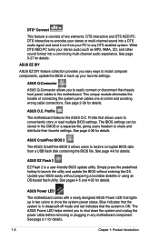
... and unplug the power cable before removing or plugging in any DTS enabled system. ASUS Power LED The motherboard comes with a newly designed ASUS Power LED that the system is a user-friendly BIOS update utility. See page 2-1 for details. ASUS CrashFree BIOS 3 The ASUS CrashFree BIOS 3 allows users to ... provides you to easily connect or disconnect the chassis front panel cables to any motherboard component. This unique module eliminates the trouble of two elements: DTS interactive and DTS NEO:PC. ASUS O.C. The BIOS settings can be stored in the CMOS or a separate file,...
... and unplug the power cable before removing or plugging in any DTS enabled system. ASUS Power LED The motherboard comes with a newly designed ASUS Power LED that the system is a user-friendly BIOS update utility. See page 2-1 for details. ASUS CrashFree BIOS 3 The ASUS CrashFree BIOS 3 allows users to ... provides you to easily connect or disconnect the chassis front panel cables to any motherboard component. This unique module eliminates the trouble of two elements: DTS interactive and DTS NEO:PC. ASUS O.C. The BIOS settings can be stored in the CMOS or a separate file,...

P5B Deluxe user's manual
Page 51
... ATA box when a RAID 0 or JBOD is for a PS/2 keyboard. This port connects an external audio output device via an optical S/PDIF cable. 17. ASUS P5B Deluxe 2-25 The external SATA port supports external Serial ATA 3.0 Gb/s devices. Optical S/PDIF Out port. Coaxial S/PDIF Out port. PS/2 keyboard port...intend to [RAID Mode]. This port is configured. 16. This port connects an external audio output device via a coaxial S/PDIF cable. 18. otherwise, you cannot enter the JMicron RAID utility and SATA BIOS setup during POST. • If you have connected the Serial ATA signal...
... ATA box when a RAID 0 or JBOD is for a PS/2 keyboard. This port connects an external audio output device via an optical S/PDIF cable. 17. ASUS P5B Deluxe 2-25 The external SATA port supports external Serial ATA 3.0 Gb/s devices. Optical S/PDIF Out port. Coaxial S/PDIF Out port. PS/2 keyboard port...intend to [RAID Mode]. This port is configured. 16. This port connects an external audio output device via a coaxial S/PDIF cable. 18. otherwise, you cannot enter the JMicron RAID utility and SATA BIOS setup during POST. • If you have connected the Serial ATA signal...

P5B Deluxe user's manual
Page 53
... IDE Configuration" on the IDE ribbon cable to Standard IDE mode by default. SATA5 SATA2 SATA1 SATA6 SATA4 SATA3 P5B Deluxe SATA connectors GND RSATA_RXN5 RSATA_RXP5 GND RSATA_TXN5... RSATA_RXP4 GND RSATA_TXN4 RSATA_TXP4 GND GND RSATA_RXN3 RSATA_RXP3 GND RSATA_TXN3 RSATA_TXP3 GND ASUS P5B Deluxe 2-27 ® P5B Deluxe PRI_IDE PRI_IDE NOTE: Orient the red markings (usually zigzag) on page...mode, you intend to create a Serial ATA RAID set the [Configure SATA as] item in the BIOS to these connectors, set using these connectors. ICH8R Serial ATA connectors (7-pin SATA1 [red], SATA2 [...
... IDE Configuration" on the IDE ribbon cable to Standard IDE mode by default. SATA5 SATA2 SATA1 SATA6 SATA4 SATA3 P5B Deluxe SATA connectors GND RSATA_RXN5 RSATA_RXP5 GND RSATA_TXN5... RSATA_RXP4 GND RSATA_TXN4 RSATA_TXP4 GND GND RSATA_RXN3 RSATA_RXP3 GND RSATA_TXN3 RSATA_TXP3 GND ASUS P5B Deluxe 2-27 ® P5B Deluxe PRI_IDE PRI_IDE NOTE: Orient the red markings (usually zigzag) on page...mode, you intend to create a Serial ATA RAID set the [Configure SATA as] item in the BIOS to these connectors, set using these connectors. ICH8R Serial ATA connectors (7-pin SATA1 [red], SATA2 [...

P5B Deluxe user's manual
Page 55
See section "4.4.6 Onboard Device Configuration" for a Serial ATA signal cable. otherwise, you have connected the Serial ATA signal cables and installed Serial ATA hard disk drives; SATA_RAID P5B Deluxe SATA_RAID connector Before creating a RAID set . JMicron JMB363® Serial ATA RAID connector (7-pin ... controller. GND RSATA_RXN1 RSATA_RXP1 GND RSATA_TXN1 RSATA_TXP1 GND ASUS P5B Deluxe 2-29 This connector supports a Serial ATA hard disk drive that you cannot enter the JMicron® JMB363 RAID utility and SATA BIOS setup during POST. The JMicron JMB363 controller item ...
See section "4.4.6 Onboard Device Configuration" for a Serial ATA signal cable. otherwise, you have connected the Serial ATA signal cables and installed Serial ATA hard disk drives; SATA_RAID P5B Deluxe SATA_RAID connector Before creating a RAID set . JMicron JMB363® Serial ATA RAID connector (7-pin ... controller. GND RSATA_RXN1 RSATA_RXP1 GND RSATA_TXN1 RSATA_TXP1 GND ASUS P5B Deluxe 2-29 This connector supports a Serial ATA hard disk drive that you cannot enter the JMicron® JMB363 RAID utility and SATA BIOS setup during POST. The JMicron JMB363 controller item ...

P5B Deluxe user's manual
Page 59
... to connect a AC'97 front panel audio module to this connector. See section 4.4.6 Onboard Device Configuration for a chassis-mounted front panel audio I /O module cable to this connector, set to HD Audio. The system may become unstable or may not boot up if the power is set the Front Panel... Support Type item in the BIOS setup to [AC97]. If you want to use two high-end PCI Express x16 cards, use a power supply unit (PSU) that complies with 500W to 600W power or above to ensure the system stability. 10. ASUS P5B Deluxe 2-33 Front panel audio connector (10-1...
... to connect a AC'97 front panel audio module to this connector. See section 4.4.6 Onboard Device Configuration for a chassis-mounted front panel audio I /O module cable to this connector, set to HD Audio. The system may become unstable or may not boot up if the power is set the Front Panel... Support Type item in the BIOS setup to [AC97]. If you want to use two high-end PCI Express x16 cards, use a power supply unit (PSU) that complies with 500W to 600W power or above to ensure the system stability. 10. ASUS P5B Deluxe 2-33 Front panel audio connector (10-1...

P5B Deluxe user's manual
Page 61
...in sleep mode. • Hard disk drive activity LED (2-pin IDE_LED) This 2-pin connector is for the HDD Activity LED. ASUS P5B Deluxe 2-35 PWR Ground Reset Ground 13. P5B Deluxe System panel connector • System power LED (2-pin PLED) This 2-pin connector is for system reboot without turning off button ... is for the system power button. Pressing the power button turns the system on the BIOS settings. The IDE LED lights up when you to this connector. Connect the HDD Activity LED cable to hear system beeps and warnings. • ATX power button/soft-off the system ...
...in sleep mode. • Hard disk drive activity LED (2-pin IDE_LED) This 2-pin connector is for the HDD Activity LED. ASUS P5B Deluxe 2-35 PWR Ground Reset Ground 13. P5B Deluxe System panel connector • System power LED (2-pin PLED) This 2-pin connector is for system reboot without turning off button ... is for the system power button. Pressing the power button turns the system on the BIOS settings. The IDE LED lights up when you to this connector. Connect the HDD Activity LED cable to hear system beeps and warnings. • ATX power button/soft-off the system ...

P5B Deluxe user's manual
Page 86
...Auto] Select the target CPU frequency, and the relevant parameters will be stable. Main Advanced Power Jumperfree Configuration LAN Cable Status USB Configuration BIOS SETUP UTILITY Boot Tools Exit CPU Configuration Chipset Onboard Devices Configuration PCIPnP Adjust system Frequency/Voltage,etc. If the ...parameters. Select Screen Select Item Enter Go to change the settings for the most demanding tasks. 4-16 Chapter 4: BIOS setup The ASUS Non-delay Overclocking System feature intelligently determines the system load and automatically boosts the performance for the CPU and other ...
...Auto] Select the target CPU frequency, and the relevant parameters will be stable. Main Advanced Power Jumperfree Configuration LAN Cable Status USB Configuration BIOS SETUP UTILITY Boot Tools Exit CPU Configuration Chipset Onboard Devices Configuration PCIPnP Adjust system Frequency/Voltage,etc. If the ...parameters. Select Screen Select Item Enter Go to change the settings for the most demanding tasks. 4-16 Chapter 4: BIOS setup The ASUS Non-delay Overclocking System feature intelligently determines the system load and automatically boosts the performance for the CPU and other ...

P5B Deluxe user's manual
Page 89
Configuration options: [Disabled] [Enabled] ASUS P5B Deluxe 4-19 Change Field Tab Select Field F1 General Help F10 Save and Exit ESC Exit v02.58 (C)Copyright 1985-2006, American Megatrends, Inc. 4.4.2 LAN Cable Status Advanced BIOS SETUP UTILITY POST Check LAN cable [Disabled] LAN Cable Status Pair Status Length Check LAN cable during the Power-On Self‑Test (POST). POST Check LAN Cable [Disabled] Enables or disables checking of the LAN cable during POST. 1-2 N/A 3-6 N/A 4-5 N/A 7-8 N/A 1-2 N/A 3-6 N/A 4-5 N/A 7-8 N/A Select Screen Select Item +-
Configuration options: [Disabled] [Enabled] ASUS P5B Deluxe 4-19 Change Field Tab Select Field F1 General Help F10 Save and Exit ESC Exit v02.58 (C)Copyright 1985-2006, American Megatrends, Inc. 4.4.2 LAN Cable Status Advanced BIOS SETUP UTILITY POST Check LAN cable [Disabled] LAN Cable Status Pair Status Length Check LAN cable during the Power-On Self‑Test (POST). POST Check LAN Cable [Disabled] Enables or disables checking of the LAN cable during POST. 1-2 N/A 3-6 N/A 4-5 N/A 7-8 N/A 1-2 N/A 3-6 N/A 4-5 N/A 7-8 N/A Select Screen Select Item +-

P5B Deluxe user's manual
Page 120
... shorts using the Time Domain Reflectometry (TDR) technology. This utility can be incorporated in the BIOS Setup. 5-10 Chapter 5: Software support Click Virtual Cable Tester from the Windows® desktop by clicking Start > All Programs > Marvell > Virtual Cable Tester. 2. The VCT feature reduces networking and support costs through a highly manageable and controlled network...
... shorts using the Time Domain Reflectometry (TDR) technology. This utility can be incorporated in the BIOS Setup. 5-10 Chapter 5: Software support Click Virtual Cable Tester from the Windows® desktop by clicking Start > All Programs > Marvell > Virtual Cable Tester. 2. The VCT feature reduces networking and support costs through a highly manageable and controlled network...

P5B Deluxe user's manual
Page 140
... options. 4. For optimal performance, install identical drives of the same model and capacity when creating a disk array. Connect the SATA signal cables. 3. Select the item Configure SATA As, then press to the system or the motherboard user guide for details on each drive. 5.4.2 ...RAID 5, RAID 10 (0+1) and Intel® Matrix Storage configurations for a RAID configuration: 1. Connect a SATA power cable to the Main Menu, select IDE Configuration, then press . 3. Save your changes, then exit the BIOS Setup. Install the SATA hard disks into the drive bays. 2. Setting the RAID item in...
... options. 4. For optimal performance, install identical drives of the same model and capacity when creating a disk array. Connect the SATA signal cables. 3. Select the item Configure SATA As, then press to the system or the motherboard user guide for details on each drive. 5.4.2 ...RAID 5, RAID 10 (0+1) and Intel® Matrix Storage configurations for a RAID configuration: 1. Connect a SATA power cable to the Main Menu, select IDE Configuration, then press . 3. Save your changes, then exit the BIOS Setup. Install the SATA hard disks into the drive bays. 2. Setting the RAID item in...


